Development of Flow Rate Feedback Control in Tilting-ladle-type
Pouring Robot with Direct Manipulation of Pouring Flow Rate
Yuta Sueki
a
and Yoshiyuki Noda
b
Department of Mechanical Engineering, University of Yamanashi, 4-3-11, Takeda, Kofu, 400-8511, Japan
Keywords:
Pouring Robot, Flow Rate Control, Extended Kalman Filter, Gain-scheduled PID Control.
Abstract:
This paper describes the advanced control technology for the tilting-ladle-type pouring robots in the casting
industry. In the pouring process in which the molten metal is poured into the pouring basin of the mold by
tilting the ladle, it is difficult to pour the molten metal as desired pouring flow rate by the operator. Because the
pouring flow rate is manipulated indirectly by manipulating the ladle’s angle. In order to solve this problem, in
previous studies, we developed the direct manipulation system of the pouring flow rate in the pouring robots.
However, the error between the desired and the actual pouring flowrate can be caused by the disturbances in the
pouring condition. Therefore, in this study, we develop the pouring flow rate feedback control for improving
the tracking performance. In this approach, the pouring flow rate can be estimated by using the extended
Kalman filter, and the feedback controller can be constructed by the gain-scheduled PID control based on the
estimated flow rate. The developed system is applied to the laboratory-type pouring robot. According to the
experiments, the operator can manipulate the pouring flow rate as desired, even in the pouring condition with
the disturbance.
1 INTRODUCTION
In the casting industry, the pouring process is dan-
gerous process because the workers use the molten
metal which has high temperature. To improve the
dangerous working environment, the pouring process
has been automated(Lindsay, 1983). In particular, a
tilting-ladle-type pouring robot is automated from the
handwork in which the molten metal is poured into
the pouring basin of the mold, and it is often used in
the casting industry since the pouring robot has sim-
ple construction and it is easy to change the types
of metal. As a control system of the tilting-ladle-
type pouring robot, the teaching-and-playbackcontrol
is often used(Watanabe and Yoshida, 1992), (Yajima
and Noda, 2018). In the teaching mode, the operator
manipulates the angle of the ladle by using the opera-
tional terminal from the remote location. The pouring
process requires to pour the molten metal precisely
into the pouring basin of the mold without spilling
out. However, to satisfy the requirement is difficult,
because the operator has to manipulate indirectly the
pouring flow rate of the outflow liquid by manipulat-
ing the tilting ladle(Voss, 2018). In order to solve this
a
https://orcid.org/0000-0002-5972-2425
b
https://orcid.org/0000-0001-8500-5529
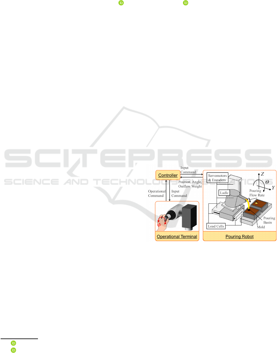
Figure 1: Tilting-ladle-type Pouring Robot.
problem, we have developed the direct manipulation
system of the pouring flow rate in the tilting-ladle-
type pouring robot(Sueki and Noda, 2017a), (Sueki
and Noda, 2018) as shown in Figure 1. In these stud-
ies, the direct flow rate manipulation system is based
on the flow rate feedforward control with the inverse
model(Noda and Terashima, 2007). The pouring flow
rate feedforward control (Noda and Terashima, 2007)
also contributes to the analyses of the falling motion
of the outflow liquid from the ladle and development
of the falling position control of the outflow liquid
to pour accurately the molten metal into the pouring
basin(Sueki and Noda, 2017b), (Ito et al., 2012).
However, the performance of the tracking to the
460
Sueki, Y. and Noda, Y.
Development of Flow Rate Feedback Control in Tilting-ladle-type Pouring Robot with Direct Manipulation of Pouring Flow Rate.
DOI: 10.5220/0007951004600467
In Proceedings of the 16th International Conference on Informatics in Control, Automation and Robotics (ICINCO 2019), pages 460-467
ISBN: 978-989-758-380-3
Copyright
c
2019 by SCITEPRESS – Science and Technology Publications, Lda. All rights reserved
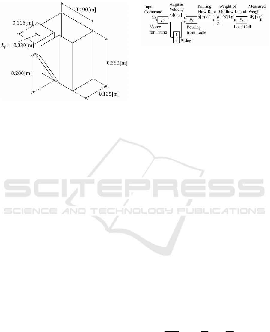
Figure 2: Geometry of Ladle.
desired flow rate can be degraded by some distur-
bances. As one of the major disturbances in the pour-
ing process, the tilting angle of the ladle at the begin-
ning of the liquid outflow is uncertain by varying the
liquid density and the surface tension.
Therefore, in this study, we develop the pouring
flow rate feedback control system for suppressing the
disturbance in the tilting-ladle-type pouring robot. To
construct the pouring flow rate feedback control, the
pouring flow rate needs to be measured while pour-
ing. However, it is difficult to measure the pouring
flow rate directly by using a flow mater because the
sensor will be damaged by the molten metal. There-
fore, the extended Kalman filter(Noda et al., 2008),
(Noda and Terashima, 2012) is applied to the devel-
oped feedback control system to estimate the pour-
ing flow rate in real time. Moreover, we propose the
gain-scheduled PID control based on the approximate
linearization of the pouring process, since the pour-
ing process is modeled as non-linear model in previ-
ous study(Noda and Terashima, 2007). In this feed-
back control system, the PID parameters are varied
in accordance with the pouring state. The developed
pouring flow rate feedback control system is applied
to the laboratory-type pouring robot and the efficacy
of the proposed approach is verified through the ex-
periments.
2 TILTING-LADLE-TYPE
POURING ROBOT
In this study, the tilting-ladle-type pouring robot as
shown in Figure 1 is used. The ladle can be trans-
ferred onY- and Z-axes and rotated on Θ-direction by
servomotors. The driving force of each motor is am-
plified through a ball-screw mechanism on the Y- and
Figure 3: Block Diagram of Pouring Process in Pouring
Robot.
Z- axes. The transfer distance and the tilting angle of
the ladle can be measured by rotary encoders installed
into the motors. The center of the ladle’srotation shaft
is placed near the ladle’s center of gravity. In case that
the ladle is rotated around the center of gravity, the tip
of the pouring mouth in the ladle moves in a circular
trajectory. It is difficult to pour the molten metal into
the pouring basin, since the pouring mouth is moved
by tilting. Therefore, the position of the tip of the
pouring mouth is controlled invariably while pouring
by means of the synchronous control of the Y- and
Z- axes for rotational motion around the ladle’s Θ-
direction(Suzuki et al., 2008). The weight of outflow
liquid can be measured by the load cells equipped on
the base of the pouring robot. In this study, the ladle
shown in Figure 2 which has the trapezoidal shape is
used. The target liquid is water for safety reason. As
the operational terminal, the joystick is used in this
study. The joystick can be rotated for tilting the la-
dle on Θ-direction. The attitude of the joystick can be
measured by the rotary encoder.
3 MATHEMATICAL MODELS OF
POURING PROCESS
Figure 3 shows the block diagram of the pouring pro-
cess which is used in this study. The input command
is applied to the motor for tilting the ladle. Then, the
liquid is poured from the ladle. The weight of the out-
flow liquid is measured by the load cell.
3.1 Motor Model
In Figure 3, the motor model P
t
for tilting the ladle is
simplified as a first-order-lag system described as
dω(t)
dt
= −
1
T
m
ω(t) +
K
m
T
m
u
t
(t), (1)
where ω[deg/s] is the angular velocity of the tilting
ladle, and u
t
is the input command applied to the mo-
tor. T
m
[s] is the time constant, and K
m
[deg/s] is the
gain constant. In this study, T
m
is 0.022[s] and K
m
is
0.980[deg/s].
Development of Flow Rate Feedback Control in Tilting-ladle-type Pouring Robot with Direct Manipulation of Pouring Flow Rate
461
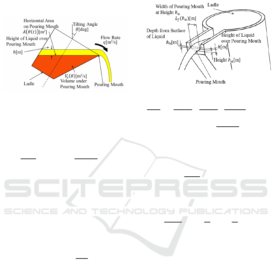
3.2 Pouring Process Model
Figure 4: Cross Section of Pouring Process.
The pouring process model P
f
in Figure 3 represents
the dynamics from the angular velocity ω to the flow
rate q[m
3
/s] of the outflow liquid. The cross section of
the pouring process is shown in Figure 4. In Figure 4,
the mass balance of the liquid in the ladle is described
as
dV
r
(t)
dt
= −q(t) −
∂V
s
(θ(t))
∂θ
ω(t), (2)
where V
r
[m
3
] is the liquid volume over the pour-
ing mouth, and V
s
[m
3
] is the liquid volume under the
pouring mouth. h[m] is the height of the liquid over
the pouring mouth. The volume V
r
[m
3
] can be repre-
sented as
V
r
(t) ≈ A(θ(t))h(t), (h ≥ 0), (3)
where, A[m
2
] is the upper surface of the liquid in
the ladle. As seen from Figure 4, the surface A is
changed by tilting angle θ[deg] of the ladle.
By using Bernoulli’s principle, the flow rate q at
the liquid height h[m] shown as
q(t) = c
Z
h(t)
0
L
f
(h
a
)
p
2gh
b
dh
b
, (4)
(0 < c ≤ 1, h
a
= h(t) − h
b
),
where L
f
[m] is the width of the pouring mouth at
the height h
a
[m] from the bottom edge of the pouring
mouth as shown in Figure 5, and h
b
[m] is the depth
at the pouring mouth from the surface of the liquid
in the ladle. c is the flow rate coefficient, which can
be identified by the comparison of the experimental
result of the measured liquid weight and the simulated
result of the load cell model. In this study, c is 0.75.
g[m/s
2
] is the acceleration of gravity.
From Eqs. (2), (3) and (4), the dynamics of the
liquid height over the pouring mouth in the pouring
process can be derived as
Figure 5: Parameters on Pouring Mouth.
dh(t)
dt
= −
q(h(t))
A(θ(t))
−
1
A(θ(t))
∂A(θ(t))
∂θ(t)
h(t)
+
∂V
s
(θ(t))
∂θ(t)
ω(t). (5)
3.3 Load Cell Model
The actual weight W[kg] of the outflow liquid can be
represented as
dW(t)
dt
= ρq(t), (6)
where ρ[kg/m
3
] is the density of the liquid. The dy-
namics of the load cell can be simplified as a first-
order-lag system. Therefore, the load cell model P
L
is
described as
dW
L
(t)
dt
= −
1
T
L
W
L
(t) +
1
T
L
W(t), (7)
where W
L
[kg] is the weight of the outflow liquid mea-
sured by the load cell, and T
L
[s] is the time constant
of the load cell. In this study, T
L
is 0.16[s].
4 POURING FLOW RATE
ESTIMATION
In this study, the state estimation is decentralized
to the motor system and the pouring process(Noda
and Terashima, 2012). In the state estimation ap-
proach, a steady-state Kalman filter is applied to
the motor model for estimating the angular veloc-
ity of the ladle and an extended Kalman filter is ap-
plied to the pouring process with the load cell model
from the angular velocity of the ladle to the mea-
sured weight by the load cell for estimating the pour-
ing flow rate.The discrete-time steady-state Kalman
filter(Noda and Terashima, 2012) is applied to the
discrete-time state equation of the motor model de-
scribed as
ICINCO 2019 - 16th International Conference on Informatics in Control, Automation and Robotics
462
ω
n+1
θ
n+1
=
1−
T
s
T
m
0
T
s
1
ω
n
θ
n
+
T
s
K
m
T
m
0
u
tn
, (8)
y
n
=
0 1
ω
n
θ
n
, (9)
where, T
s
[s] represents the sampling interval and it is
determined 0.020[s] in this study. By applying the es-
timated angular velocity
¯
ω[deg/s] to the pouring pro-
cess model, the pouring flow rate can be estimated.
To estimate the pouring flow rate, we used
the discrete-time extended Kalman filter(Noda and
Terashima, 2012). The discrete-time extended
Kalman filter is applied to the discrete-time state
equation can be represented as
x
n+1
= f(x
n
), (10)
y
n
= η(x
n
), (11)
where,
x =
h W W
L
T
, (12)
f(x) =
1−
T
s
A(θ)
∂A(θ)
∂θ
¯
ω
h
−
T
s
q(h)
A(θ)
¯
ω−
T
s
A(θ)
∂V
s
(θ)
∂θ
¯
ω
W + T
s
ρq(h)
(1−
T
s
T
L
)W
L
+
T
s
T
L
W
, (13)
η(x) = W
L
. (14)
Then, the estimated pouring flow rate ¯q[m
3
/s] can be
obtained from the estimated liquid height
¯
h[m] as
¯q(
¯
h(t)) = c
Z
¯
h(t)
0
L
f
(h
a
)
p
2gh
b
dh
b
. (15)
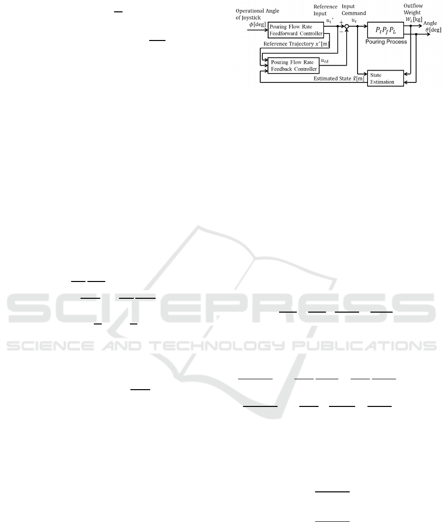
5 POURING FLOW RATE
FEEDBACK CONTROL
The pouring flow rate feedback control system in the
tilting-ladle-type pouring robot with direct manipu-
lation of flow rate is shown as Figure 6. In Figure
6, the operational angle of joystick is applied to the
pouring flow rate feedforward controller(Sueki and
Noda, 2018) which is based on the inverse model of
the pouring process. Then, the reference trajectory
and the reference input can be generated. In other
words, the 2-DOF flow rate control system is con-
structed by integrating the flow rate feedforward and
feedback control systems.
Figure 6: Block Diagram of Pouring Flow Rate Feedback
Control in Operational Pouring Robot with Manipulatable
Pouring Flow Rate.
5.1 Approximate Linearization of
Pouring Process
The pouring process model in the previous
study(Noda and Terashima, 2007) is the non-
linear model described as Eq. (5). Therefore, the
poring process model is linearized approximately to
design the feedback control system. In particular,
the state equation of the liquid height in the pouring
process is linearized approximately around the oper-
ating point. The mathematical model of the pouring
process can be represented as
x = h, ˙x = f (x, u
t
), (16)
f(x, u
t
) = −
q(h)
A(θ)
−
1
A(θ)
∂V
s
(θ)
∂θ
+
∂A(θ)
∂θ
h
K
m
u
t
.
(17)
the partial derivatives of state x and input command
u
t
are described respectively as
∂f(x, u
t
)
∂x
= −
1
A(θ)
∂q(h)
∂h
−
1
A(θ)
∂A(θ)
∂θ
K
m
u
t
, (18)
∂f(x, u
t
)
∂u
t
= −
1
A(θ)
∂V
s
(θ)
∂θ
+
∂A(θ)
∂θ
h
K
m
. (19)
By using the deviations x
δ
, u
tδ
around the operat-
ing point, the approximate linearized pouring process
model can be represented as
˙x
δ
= A
x
(x
∗
, u
∗
t
)x
δ
+ B
x
(x
∗
, u
∗
t
)u
tδ
, (20)
A
x
(x
∗
, u
∗
t
) =
∂f(x, u
t
)
∂x
x=x
∗
,u
t
=u
∗
t
,
B
x
(x
∗
, u
∗
t
) =
∂f(x, u
t
)
∂u
t
x=x
∗
,u
t
=u
∗
t
,
x
δ
= x− x
∗
, u
tδ
= u
t
− u
∗
t
, (21)
where, x
∗
and u
∗
t
mean the reference trajectory and the
input command for realizing the reference trajectory,
respectively.
Development of Flow Rate Feedback Control in Tilting-ladle-type Pouring Robot with Direct Manipulation of Pouring Flow Rate
463

5.2 Gain-scheduled PID Control
In this section, the gain-scheduled PID control which
has the variable gains corresponding to the pouring
state is derived. The control law is described as
u
tδ
= −K
P
(x
∗
, u
∗
t
)x
δ
− K
I
(x
∗
, u
∗
t
)
Z
x
δ
dt − K
D
˙x
δ
. (22)
By substituting Eq. (22) to Eq. (20), the state equation
can be represented as
˙x
δ
= A
x
(x
∗
, u
∗
t
)x
δ
− B
x
(x
∗
, u
∗
t
)K
P
(x
∗
, u
∗
t
)x
δ
−B
x
(x
∗
, u
∗
t
)K
I
(x
∗
, u
∗
t
)
Z
x
δ
dt − B
x
(x
∗
, u
∗
t
)K
D
˙x
δ
, (23)
where, K
P
, K
I
and K
D
are the proportional gain,
the integral gain and the derivative gain respectively.
Then, a new variable z =
R
x
δ
dt is defined and the
state equation for z can be represented as
d
dt
z
˙z
= A
z
(x
∗
, u
∗
t
)
z
˙z
, (24)
A
z
(x
∗
, u
∗
t
) =
0 1
a
z21
a
z22
,
a
z21
= −
B
x
(x
∗
, u
∗
t
)K
I
(x
∗
, u
∗
t
)
1+ B
x
(x
∗
, u
∗
t
)K
D
,
a
z22
=
A
x
(x
∗
, u
∗
t
) − B
x
(x
∗
, u
∗
t
)K
P
(x
∗
, u
∗
t
)
1+ B
x
(x
∗
, u
∗
t
)K
D
.
The characteristic equation of Eq. (24) is described as
s
2
− a
z22
s− a
z21
= 0. (25)
The generalized form of second-order-lag system can
be represented as
s
2
+ 2ζω
n
s+ ω
2
n
= 0, (26)
where, ω
n
[rad/s] is a natural angular frequency and ζ
is a damping ratio. Then, the pole s can be derived as
s = −ζω
n
± ω
n
q
1− ζ
2
i. (27)
By comparing Eq. (25) with Eq. (26), PID parameters
can be derived as
K
P
(x
∗
, u
∗
t
) =
A
x
(x
∗
, u
∗
t
) + 2ζω
n
B
x
(x
∗
, u
∗
t
)
−2ζω
n
K
D
, (28)
K
I
(x
∗
, u
∗
t
) =
ω
2
n
B
x
(x
∗
, u
∗
t
)
+ ω
2
n
K
D
, (29)
K
D
= const. (30)
In this study, PID parameters are designed by the
pole assignment method. The criteria for deciding the
poles of Eq. (24) are the following:
• The real parts of the poles should be negative;
• The system should not vibrate;
• It is possible to apply the generated input com-
mand by PID controller to the controlled object.
Depending on these criteria, we obtained s = −2.0±
0i and the parameters included in s are ω
n
= 2.0[rad/s]
and ζ = 1.0 in this study.
In the PID parameters, the proportional gain K
P
and the integral gain K
I
can be obtained uniquely, and
the derivative gain K
D
can be decided arbitrarily. To
obtain K
D
which can be implemented to the pouring
robot, K
D
is applied to the pouring robot and steadily
increased. In this study, it was confirmed that the ex-
perimental equipment vibrated in case that K
D
was
applied. Because K
D
can increase the noise depend-
ing on the measured weight by the load cell. Thus,
the derivative gain is obtained as K
D
= 0 and this con-
dition means that PI controller is constructed as the
feedback controller for the experimental verification.
6 EXPERIMENTAL
VERIFICATION
Figure 7 shows the laboratory-type pouring robot
used in this study. The operator uses the joystick
as shown in Figure 7(b) as the operational terminal.
By rotating the joystick in Φ- direction, the liquid is
poured from the ladle.
6.1 Direct Manipulation of Pouring
Flow Rate
The direct manipulation of pouring flow rate is ap-
plied to the laboratory-type pouring robot and the ef-
ficacy of this manipulation approach is verified in the
ideal condition which is without the disturbances. In
other words, the direct manipulation system is con-
structed with the flow rate feedforward controller and
without flow rate feedback controller. Also, the direct
manipulation of pouring flow rate is compared with
the ladle’s angular velocity control which is used in
practical conditions. In the experiments, the opera-
tor try to pour the liquid as steady flow rate. The re-
sults of the pouring motion with the angular velocity
control and with the proposed approach are shown in
Figures 8 and 9 respectively. Figure 8(a) shows the
operational angle of joystick. (b) shows the angular
velocity of the ladle estimated by using the steady-
state Kalman filter. (c) shows the tilting angle of the
ladle measured by the encoder. (d) and (e) show the
liquid height on the pouring mouth of the ladle and
the pouring flow rate respectively. The dashed lines
are the simulated results obtained by applying above
ICINCO 2019 - 16th International Conference on Informatics in Control, Automation and Robotics
464
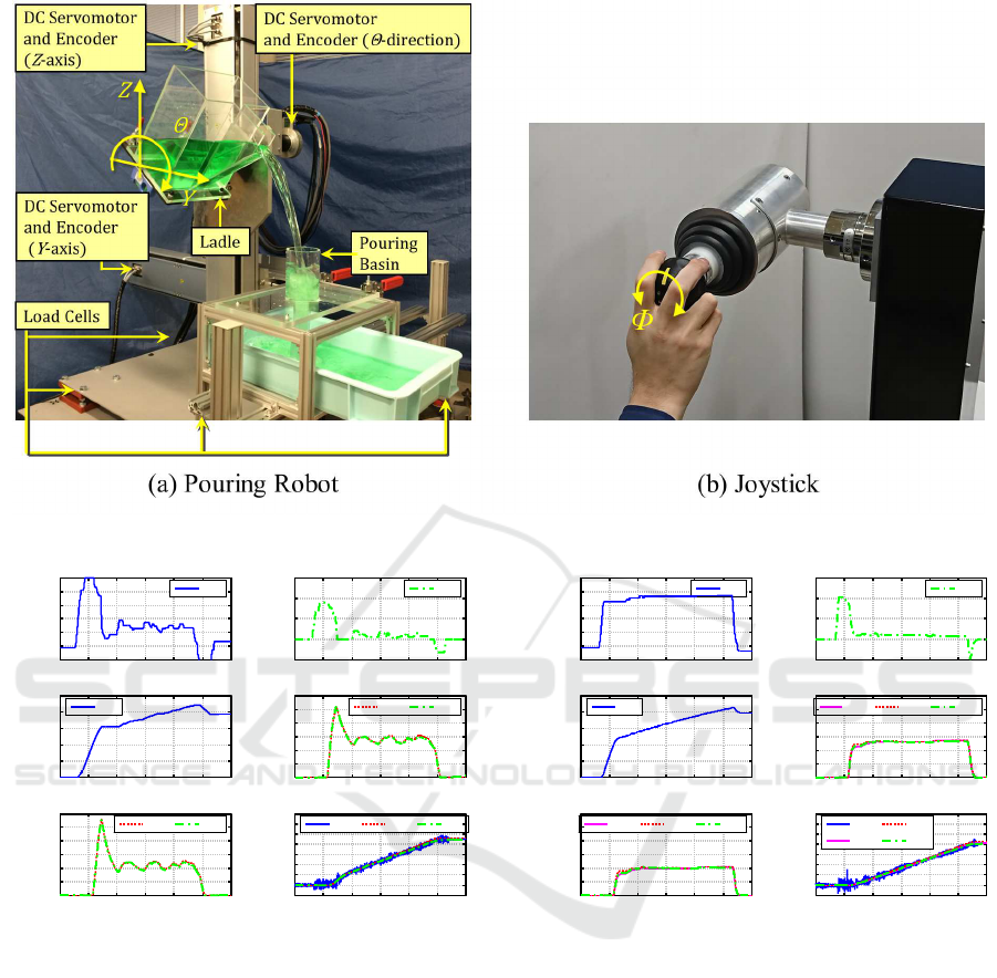
Figure 7: Laboratory-type Pouring Robot.
-5
0
5
10
15
20
25
0 5 10 15 20 25 30
Angle of
Joystick[deg]
Exp.
-5
0
5
10
15
0 5 10 15 20 25 30
Angular
Velocity[deg/s]
Est.
0
10
20
30
40
50
0 5 10 15 20 25 30
Angle[deg]
Exp.
0
0.005
0.01
0.015
0.02
0.025
0.03
0 5 10 15 20 25 30
Liquid Height[m]
Sim. Est.
0
0.5
1
1.5
2
2.5
3
0 5 10 15 20 25 30
Pouring Flow
Rate[m
3
/s]
Time[s]
x10
-4
Sim. Est.
-0.5
0
0.5
1
1.5
2
2.5
3
3.5
0 5 10 15 20 25 30
Outflow Weight[kg]
Time[s]
Exp. Sim. Est.
(a) (b)
(c)
(d)
(e)
(f)
Figure 8: Experimental Results of Pouring Motion with An-
gular Velocity Manipulation.
results (b) and (c) to Eq. (5). The chained lines are
the estimated results by using the extended Kalman
filter(EKF). Figure 8(f) shows the weight of the out-
flow liquid. The blue solid line is the measure result
by using the load cell and the other lines are in the
same manner as (d) and (e). In Figure 9(d), (e) and
(f), the magenta solid lines are the reference value de-
signed before pouring. The other lines are shown in
the same manner as Figure 8. According to Figure 8,
it is shown that the operator manipulated the angular
velocity of the ladle by using the joystick and indi-
rectly manipulated the pouring flow rate. On the other
hand, Figure 8 shows that the pouring flow rate is sim-
ilar to the operational angle of the joystick. From
these results, it was confirmed that the operator can
-5
0
5
10
15
20
25
0 5 10 15 20 25 30
Angle of
Joystick[deg]
Exp.
-5
0
5
10
15
0 5 10 15 20 25 30
Angular
Velocity[deg/s]
Est.
0
10
20
30
40
50
0 5 10 15 20 25 30
Angle[deg]
Exp.
0
0.005
0.01
0.015
0.02
0.025
0.03
0 5 10 15 20 25 30
Liquid Height[m]
Ref. Sim. Est.
0
0.5
1
1.5
2
2.5
3
0 5 10 15 20 25 30
Pouring Flow
Rate[m
3
/s]
Time[s]
x10
-4
Ref. Sim. Est.
-0.5
0
0.5
1
1.5
2
2.5
3
3.5
0 5 10 15 20 25 30
Outflow Weight[kg]
Time[s]
Exp.
Ref.
Sim.
Est.
(a) (b)
(c)
(d)
(e)
(f)
Figure 9: Experimental Results of Pouring Motion with Di-
rect Manipulation of Pouring Flow Rate without flow rate
feedback control.
manipulate the pouring flow rate directly and pour the
liquid as steady flow rate by using the developed sys-
tem.
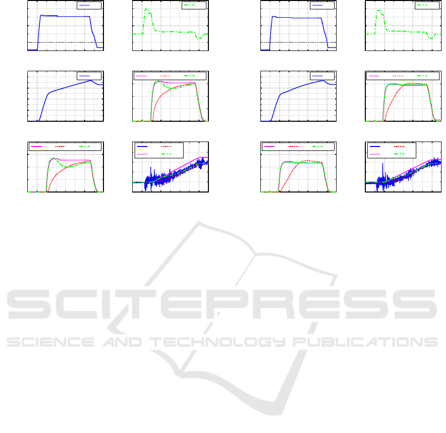
6.2 Flow Rate Feedback Control with
Direct Manipulation of Pouring
Flow Rate
The pouring flow rate feedback control system shown
as Figure 6 is applied to the laboratory-type pouring
robot as shown in Figure 7. In the experiments, the
ideal angle of the ladle at the beginning of the liq-
uid outflow is 20[deg]. However, the beginning of
Development of Flow Rate Feedback Control in Tilting-ladle-type Pouring Robot with Direct Manipulation of Pouring Flow Rate
465
0
5
10
15
20
25
30
0 2 4 6 8 10 12 14 16
Angle of
Joystick[deg]
Exp.
-10
-5
0
5
10
15
20
0 2 4 6 8 10 12 14 16
Angular
Velocity[deg/s]
Est.
0
5
10
15
20
25
30
35
40
45
0 2 4 6 8 10 12 14 16
Angle[deg]
Exp.
0
0.005
0.01
0.015
0.02
0 2 4 6 8 10 12 14 16
Liquid Height[m]
Ref. Sim. Est.
0
0.5
1
1.5
2
0 2 4 6 8 10 12 14 16
Pouring Flow
Rate[m
3
/s]
Time[s]
x10
-4
Ref. Sim. Est.
-0.5
0
0.5
1
1.5
2
0 2 4 6 8 10 12 14 16
Outflow Weight[kg]
Time[s]
Exp.
Ref.
Sim.
Est.
(a)
(b)
(c)
(d)
(e)
(f)
Figure 10: Experimental Results of Pouring Motion with
only Flow Rate Feedforward Control in Previous Approach.
liquid outflow is delayed by the disturbance which is
similar to the practical condition. To create the dis-
turbance, the actual volume of the liquid in the ladle
is less than with the ideal volume. The ideal volume
means the volume in case that the liquid in the ladle
can be poured at the ideal angle. Thus, the tilting an-
gle of the ladle at the beginning of the liquid outflow
is larger than the ideal angle. In this study, the error
of the tilting angle of the ladle at the beginning of the
liquid outflow is +3[deg] and this error is caused by
the disturbance.
Figures 10 and 11 are the results of the pouring
motion with and without the pouring flow rate feed-
back control system respectively. In addition, Figures
10 and 11 are shown in the same manner as Figure 9.
According to the results in case without the pouring
flow rate feedback control system as shown in Figure
10(e), the simulated pouring flow rate was not able
to reach the reference pouring flow rate until near the
13[s] mark in time-series data. On the other hand,
Figure 11(d) in case with the pouring flow rate feed-
back control system shows that the simulated pouring
flow rate was able to reach the reference pouring flow
rate near the 8[s] mark. Then, the simulated result
tracked the reference value.
7 CONCLUSIONS
In this study, we developedthe pouring flow rate feed-
back control in the tilting-ladle-type pouring robot
with direct manipulation of pouring flow rate. In the
0
5
10
15
20
25
30
0 2 4 6 8 10 12 14 16
Angle of
Joystick[deg]
Exp.
-10
-5
0
5
10
15
20
0 2 4 6 8 10 12 14 16
Angular
Velocity[deg/s]
Est.
0
5
10
15
20
25
30
35
40
45
0 2 4 6 8 10 12 14 16
Angle[deg]
Exp.
0
0.005
0.01
0.015
0.02
0 2 4 6 8 10 12 14 16
Liquid Height[m]
Ref. Sim. Est.
0
0.5
1
1.5
2
0 2 4 6 8 10 12 14 16
Pouring Flow
Rate[m
3
/s]
Time[s]
x10
-4
Ref. Sim. Est.
-0.5
0
0.5
1
1.5
2
0 2 4 6 8 10 12 14 16
Outflow Weight[kg]
Time[s]
Exp.
Ref.
Sim.
Est.
(a)
(b)
(c)
(d)
(e)
(f)
Figure 11: Experimental Results of Pouring Motion with
Flow Rate Feedback Control and Flow Rate Feedback Con-
trol in Proposed Approach.
developed system, the extended Kalman filter is ap-
plied to estimate the pouring flow rate in real time.
To construct the feedback control system, the approx-
imate linearization model of the pouring process is
derived since the mathematical model of the pour-
ing process has non-linear system. By using the ap-
proximate linearization model, we proposed the gain-
scheduled PID control which has variable gain de-
pending on the pouring state. In this approach, PID
parameters can be designed by the pole assignment
method. The developed feedback control system was
applied to the laboratory-type pouring robot to verify
the efficacy of the proposed approach. In the exper-
iments, firstly, we demonstrated that the efficacy of
the direct manipulation of the pouring flow rate, and it
was shown that the operator can manipulate the pour-
ing flow rate as desired. Then, the pouring flow rate
feedback control is applied to the pouring robot and
the efficacy is verified. Through the experiments, it
was confirmed that the pouring flow rate can track the
desired flow rate by the operator even in the condition
with disturbance.
In our future work, in order to operate more easily
and safely the tilting-ladle-typepouring robot with the
direct manipulation system of the pouring flow rate, a
suitable interface between the operator and the pour-
ing robot will be developed.
ICINCO 2019 - 16th International Conference on Informatics in Control, Automation and Robotics
466

REFERENCES
Ito, A., Noda, Y., and Terashima, K. (2012). Outflow liquid
falling position control by considering lower position
and clash avoidance with mold. In Preprints of the
IFAC Workshop on Automation in the Mining, Mineral
and Metal Industries, pp. 240-245.
Lindsay, W. (1983). Automatic pouring and metal distribu-
tion system. In Foundry Trade Journal, pp. 151-176.
Noda, Y., Matsuo, Y., Terashima, K., and Zheng, Y. (2008).
A novel flow rate estimation method using extended
kalman filter and sensor dynamics compensation with
automatic casting pouring process. In Proceedings
of the 17th IFAC World Congress(IFAC’08), pp. 710-
715.
Noda, Y. and Terashima, K. (2007). Modeling and feed-
forward flow rate control of automatic pouring system
with real ladle. In Journal of Robotics and Mecha-
tronics, Vol. 19, No. 2, pp. 205-211.
Noda, Y. and Terashima, K. (2012). Simplified flow rate
estimation by decentralization of kalman filters in au-
tomatic pouring robot. In Proceedings of SICE Annual
Conference 2012, pp. 1465-1470.
Sueki, Y. and Noda, Y. (2017a). Falling position control
of outflow liquid from ladle in automatic pouring ma-
chine with manipulatable flow rate. In Proceedings of
2017 IEEE/SICE International Symposium on System
Integration, WeC2.5.
Sueki, Y. and Noda, Y. (2017b). Optimal positioning of la-
dle in automatic pouring machine in consideration of
pouring liquid accurately into sprue. In Proceedings
of 2017 IEEE International Conference on Advanced
Intelligent Mechatronics(AIM), pp. 897-903.
Sueki, Y. and Noda, Y. (2018). Operational assistance sys-
tem with direct manipulation of flow rate and falling
position of outflow liquid in tilting-ladle-type pouring
machine. In Proceedings of The 73rd World Foundry
Congress, pp. 325-326.
Suzuki, M., Yang, Y., Noda, Y., and Terashima, K.
(2008). Sequence control of automatic pouring
system. In Proceedings of 10th Asian Foundry
Congress(AFC10), pp. 88-92.
Voss, T. (2018). Optimization and control of modern ladle
pouring process. In Proceedings of The 73rd World
Foundry Congress, pp. 497-498.
Watanabe, J. and Yoshida, K. (1992). Automatic pouring
equipement for casting - mel pore system. In Indus-
trial Heating, (in Japanese), Vol. 29, No. 4, pp. 19-27.
Yajima, T. and Noda, Y. (2018). Teaching-and-playback
approach based on pouring flow rate in tilting-ladle-
type pouring machine. In Proceedings of The 73rd
World Foundry Congress, pp. 137-138.
Development of Flow Rate Feedback Control in Tilting-ladle-type Pouring Robot with Direct Manipulation of Pouring Flow Rate
467
