
Investigation of Non-circular Scanning Trajectories in Robot-based
Industrial X-ray Computed Tomography of Multi-material Objects
Peter Landstorfer
1
, Gabriel Herl
2
and Jochen Hiller
1,2
1
Fraunhofer Application Center CTMT, Dieter-G
¨
orlitz-Platz 2, 94469 Deggendorf, Germany
2
Deggendorf Institute of Technology, Dieter-G
¨
orlitz-Platz 1, 94469 Deggendorf, Germany
Keywords:
X-ray Computed Tomography, X-ray Simulation, Robotics, Robot-based Imaging, Scanning Trajectory.
Abstract:
In this work the application of six-axis robots for robot-based industrial X-ray computed tomography (CT)
imaging is investigated. In contrast to classical Cartesian manipulators with a turntable used in industrial
cone-beam CT, robots offer increased flexibility regarding scanning trajectories. The increased flexibility
with respect to scanning trajectories helps to gather highly informative content from alternative ray paths for
a high-quality 3D reconstruction of the object to be scanned. Using numerical simulations we show that
this additional informations increase the image quality of a CT scan of a multi-material measuring object,
consisting of tantalum spheres and a carbon structure.
1 INTRODUCTION
Industrial X-ray computed tomography (CT) nowa-
days is an important non-destructive testing method
and is well established in production industry as a
flexible tool for quality assurance and process opti-
mization (De Chiffre et al., 2014). Since time-to-
market constantly decreases in industry, sensing and
automation technology is seen as a key technology
to develop the autonomous production of the future.
For imaging technologies like CT it is therefore con-
sequent, to work on CT systems based on flexible
robotic manipulators. Medical CT systems are al-
ready equipped with robotic manipulator (Fieselmann
et al., 2016), (Ouadah et al., 2017), (Zhao et al.,
2019), industrial robot-based CT systems are arising
as well, for example, used for quality control in the
automotive industry. The robot’s advantage compared
to classical Cartesian manipulators in CT is its flexi-
bility to reach a wider range of positions in space. Ac-
quisition trajectories beyond a single circular one can
be advantageous with respect to the resulting image
quality in industrial as well in medical applications
(Herl et al., 2019), (Noo et al., 1998), (Katsevich,
2005), (Ouadah et al., 2017). The increased flexibility
with respect to scanning trajectories helps to gather
highly informative content from alternative ray paths
(X-ray projections), resulting in high-quality 3D re-
constructions of the object to be scanned. Particu-
larly, when scanning multi-material specimens, con-
sisting of low and high absorbing materials, addi-
tional ray paths prevent the formation of metal arti-
facts to a certain extent. In this paper, the advantages
of non-circluar trajectories using a virtual Kuka KR
15-2 robot are shown by means of numerical simu-
lations, whereas positioning errors of the (real) robot
are neglected in the simulation.
2 X-RAY COMPUTED
TOMOGRAPHY
X-ray based inspection is widely used in industrial
manufacturing (De Chiffre et al., 2014). The dif-
ference between X-ray inspection systems based on
radiographs and X-ray CT is the fact that CT uses
plenty of X-ray projection images to reconstruct the
inner structure of a specimen in terms of a 3D voxel
volume. Each voxel represents the local attenuation
coefficient of a workpiece (material) to be scanned.
Typically, those voxel datasets are displayed as gray-
value slice images or a 3D rendering image as shown
exemplary in Figure 2. Usually, projection images are
generated in a circular trajectory on a machine bed us-
ing a Cartesian manipulator system with a turntable as
shown in Figure 1. In such a setup, X-ray source and
detector remain fixed and the specimen, placed on the
turntable, turns around in, e.g., 1000 angle steps. In
each angle step, the X-ray detector acquires one pro-
518
Landstorfer, P., Herl, G. and Hiller, J.
Investigation of Non-circular Scanning Trajectories in Robot-based Industrial X-ray Computed Tomography of Multi-material Objects.
DOI: 10.5220/0007966405180522
In Proceedings of the 16th International Conference on Informatics in Control, Automation and Robotics (ICINCO 2019), pages 518-522
ISBN: 978-989-758-380-3
Copyright
c
2019 by SCITEPRESS – Science and Technology Publications, Lda. All rights reserved
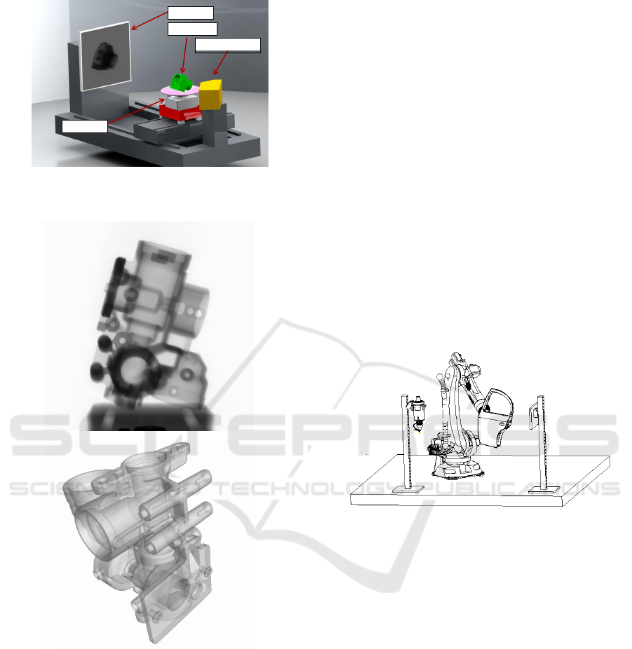
Detector
Specimen
X-ray Source
Turntable
Figure 1: Schematic illustration of a standard cone-beam
CT scanner using a circular trajectory.
Figure 2: Projection image (top) and 3D rendering image
(below) of a casting.
jection image. This set of projection images is then
reconstructed to a 3D voxel volume (De Chiffre et al.,
2014).
3 BENEFITS OF NON-CIRCULAR
TRAJECTORY
In this work, we focus on two advantages for the ap-
plication of non-circular scanning trajectories. A pos-
sible system configuration is shown in Figure 3.
In industrial CT there are several mathematical
and physical conditions and limitations that restrict
the obtained image quality of a CT image. First of all,
in circular cone-beam CT there is a data-sufficiency
problem: In order to reconstruct a 3D volume mathe-
matically correct, projection data from certain direc-
tions are needed that fulfill the so-called Tuy-Kirillov
conditions (Tuy, 1983). The most important one of
these conditions states that every plane that intersects
the volume has to intersect the trajectory of the X-ray
source. Using a circular trajectory, this condition can
be fulfilled for all volume points in the middle plane,
but not in other planes of the volume. Therefore, the
further the point is away from the source plane and
the higher the aperture angle, the stronger the form-
ing of image artifacts (so called cone-beam or Feld-
kamp artifacts) in the resulting dataset will be. By
using robots and adapting the scanning trajectory, the
Tuy-Kirillov conditions can be fulfilled, resulting in a
high-quality CT image.
Figure 3: Schematic illustration of a possible CT scanner
setup using a robot as manipulator.
Secondly, most reconstruction methods assume a
linear model of penetration length and attenuation
based on Lambert-Beer’s law in order to calculate
the local attenuation coefficient of a material. But as
the spectrum of X-ray sources is polychromatic, this
model is not true. As a consequence, one is faced
with beam-hardening and metal artifacts, especially
when scanning objects consisting of low and high ab-
sorbing materials, for example multi-material objects
made from metal and plastic. Some of the measured
and attenuated X-rays contain information that cannot
be interpreted correctly by the used models, result-
ing in beam-hardening and metal artifacts. Therefore,
these strongly attenuated X-rays should be ignored by
the reconstruction algorithm.
In order to fulfill the mentioned Tuy-Kirillov con-
ditions, projections from different directions are nec-
essary. For example, using projections from several
tilted circular trajectories and using only attenuation
values of specific X-rays can increase the image qual-
Investigation of Non-circular Scanning Trajectories in Robot-based Industrial X-ray Computed Tomography of Multi-material Objects
519
ity and the dimensional accuracy of reconstructed ob-
jects significantly (Herl et al., 2019). In this work,
we show that image artifacts due to almost total ab-
sorption can be decreased by using a robot and a non-
circular scanning trajectory.
4 ROBOTS AS MANIPULATORS
In this work, we investigated a robot-based CT as
shown in Figure 3. Using such a setup, source
and detector are mounted in fixed positions and the
robot handles (manipulates) the specimen. Besides
this setup, other configurations are possible. Med-
ical CT scanners for example use a C-bow to han-
dle source and detector using one robot (Fieselmann
et al., 2016). Other configurations are based on one
robot for source and one to handle the detector while
the specimen remains fixed. It is further possible to
use robots on linear rails to further enhance the work-
ing volume or to additionally use a turntable.
Generally speaking, it can be said from a theoret-
ical point of view that, the more directions a voxel
is scanned from, the higher the image quality of the
resulting reconstructed volume will be. Thus, a scan-
ner fully performing a sphere-like trajectory would be
ideal to penetrate each voxel out of every possible di-
rection. However, this can not even be achieved by
a six-axis robot. The reasons are: The specimen in
mounted on a fixture and source and detector can not
move into that fixture. For some positions, the robot’s
hand would mask the cone-beam. Those projections
also have to be omitted. Further, even a six-axes in-
dustrial robot can not reach any position and orienta-
tion in its working volume due to its joint angle limits.
Figure 4 shows possible projection positions
(green area) the robot can approach based on the
conditions mentioned before using numerical calcula-
tions based on geometric assumptions. Using homo-
geneous coordinates and Denavit-Hartenberg param-
eters, the possible positions the robot can approach
were determined.
5 EXPERIMENT: SIMULATION
STUDY
As mentioned earlier, the robot can not reach all
spatial positions on the virtual sphere. We deter-
mined the feasible positions using geometric assump-
tions. Using homogeneous coordinates and Denavit-
Hartenberg parameters of the Kuka KR 15-2 robot,
the possible positions of the robot can be estimated.
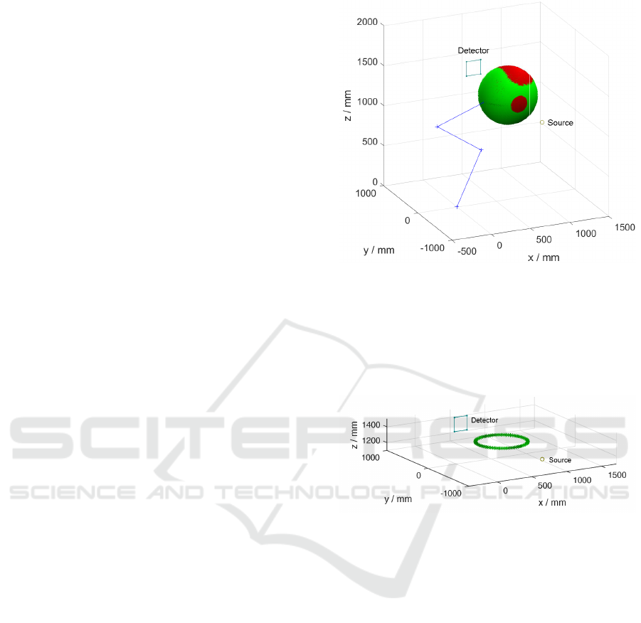
Figure 4: Calculated projection positions in space for the
non-circular case: The robot main axes are visualized as
blue lines, reachable projection positions as green area,
unreachable ones as red area. The robot base flange is
mounted on the x/y plane and reaches the projection po-
sitions with its tool flange (TCP), pointing to the center of
the object. The X-ray source is visualized as a circle and
the X-ray detector as a square.
Figure 5: Projection positions for a standard circular CT
scan using a turntable. The X-ray source is visualized as a
circle and the X-ray detector as a square.
In this simulation experiment, the center of the ob-
ject was located x = 650 mm and z = 1300 mm from
the base flange of the robot. Further, a distance from
the center of the object to the tool flange of the robot
of 200 mm was modeled as specimen fixture. In a
real approach, one would build up this fixture of low
density foam material in order not to compromise the
imaging process. Ideally, the robot could turn the
specimen around in a full sphere so that the X-ray sys-
tem can gather information from all directions. Due to
certain technical limitations, this is not possible. We
cannot reach some positions on top of the sphere be-
cause of the robots wrist angular range limit of ±135
degrees. Further we omitted those positions where
the hand of the robot moves into the relevant X-ray
beams. All positions inside a cylinder of 200 mm in
diameter with the central X-ray as center line were
omitted. Using a 5 degree pattern for azimuth angle
from 0 to 355 degree and elevation from 0 to 175 de-
ICINCO 2019 - 16th International Conference on Informatics in Control, Automation and Robotics
520
gree, in total 1859 spatial coordinates deliver the po-
sition data for the following simulations.
The output of our calculation is a set of spatial
coordinates (see Figure 4) we passed over to our
X-ray simulation tool XLab from Fraunhofer EZRT
(Reisinger et al., 2011). We computed noise-free vir-
tual projections of the virtual specimen out of carbon
as shown in Figure 6 using the X-ray simulation pa-
rameters, summarized in Table 1.
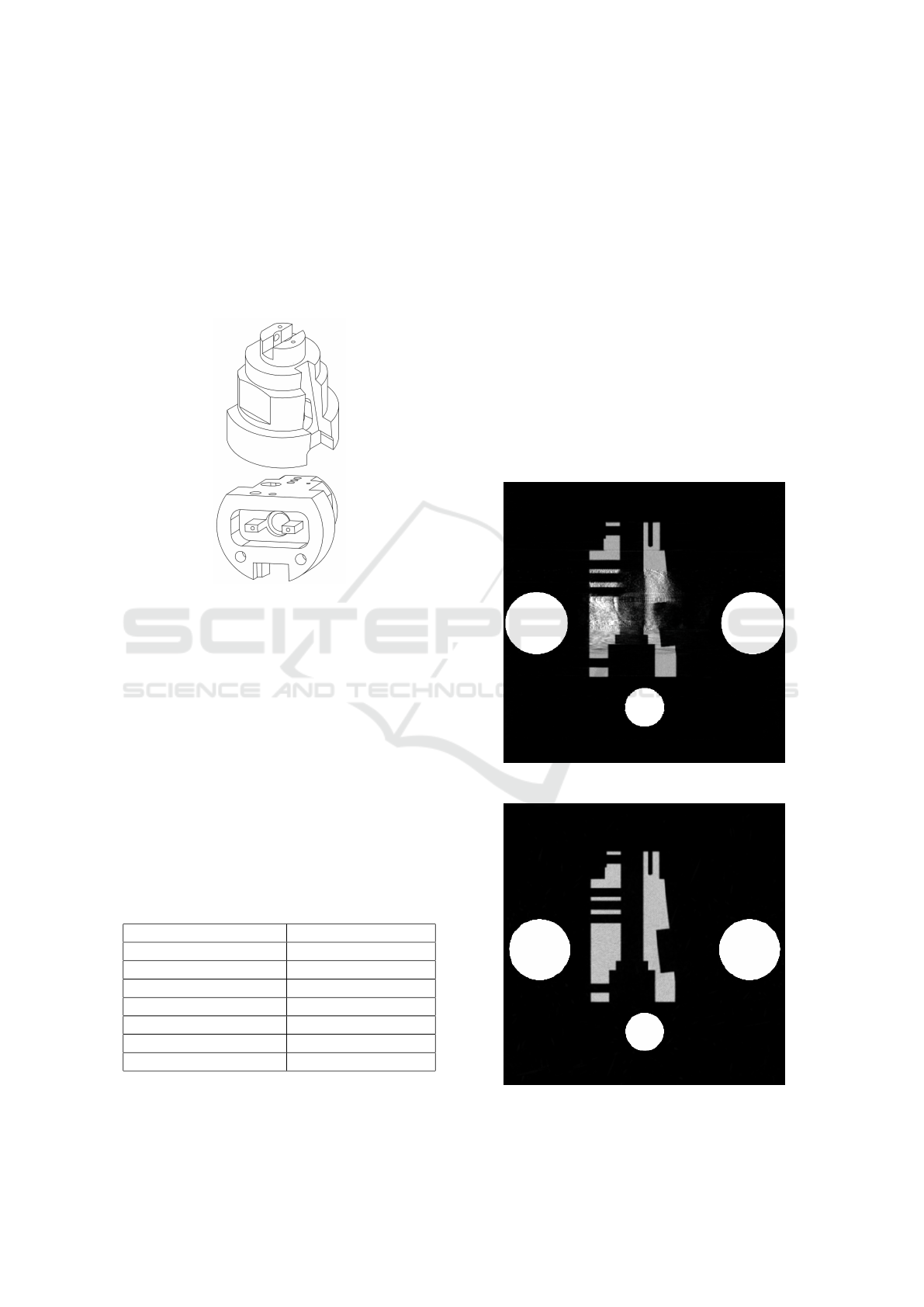
Figure 6: The simulated specimen is 3 cm tall and made out
of carbon.
In order to clearly show the benefits of non-
circular CT scanning trajectories, we additionally
modeled four tantalum spheres of 6.5 millimeter di-
ameter and one sphere of 4 millimeter in diameter
and added it to the virtual specimen, so that it can
be treated as a multi-material object with low and
high density material contributions. For 3D recon-
struction to a voxel volume, we used a modified alge-
braic reconstruction technique (ART) (see (Herl et al.,
2019)).
In total, we simulated one non-circular (see Fig-
ure 4) and one circular (see Figure 5) trajectory. The
results of the simulations are summarized in the fol-
lowing section.
Table 1: Simulation parameters.
Specimen materials Tantalum and carbon
Tube voltage 225 kV
Tube current 0.02 mA
Focus detector distance 2000 mm
Magnification factor 2
Detector pixel size 0.469 mm
Detector pixel grid 512 × 512 pixels
Detector noise off
6 RESULTS
The results of the simulations in term of slice im-
ages using the two different scanning trajectories are
shown in Figure 7 and Figure 8.
When comparing Figure 7 and 8 we can clearly
see that the non-circular CT trajectory results in a
much higher image quality (no streak artifacts) due
to the fact that the additional information from the
non-circular trajectory compensates the impact of al-
most fully absorbed rays (due to the high dense tanta-
lum spheres) in the reconstructed volume and, as con-
sequence, reduces image artifacts significantly. The
circular trajectory mainly suffers from partial total
absorption due to the high density tantalum, where
the non-circular trajectory, performed by the (virtual)
robot, suffers much less from those physical restric-
tions.
Figure 7: Reconstruction using circular scanning.
Figure 8: Reconstruction using non-circular scanning.
Investigation of Non-circular Scanning Trajectories in Robot-based Industrial X-ray Computed Tomography of Multi-material Objects
521

7 CONCLUSIONS AND
OUTLOOK
We investigated a non-circular trajectory for robot-
based X-ray CT and its application for the reconsti-
tution of a multi-material object using numerical sim-
ulations. Within the study we calculated a set of fea-
sible robot positions to obtain a set of X-ray projec-
tion images to reconstruct a voxel dataset. Further, we
simulated a standard circular CT and visually com-
pared the results of the two reconstructions qualita-
tively. We have shown that when using additional
information from different non-circular directions, a
much higher image quality can be expected in contrast
to a standard circular scan. Future work will focus
on optimization methods for robot CT path planning,
taking trajectory and accuracy limitations of robots,
material and geometrical properties of various speci-
mens as well as object and scan-specific X-ray inter-
action effects into account. Furthermore, experiments
using a real robot-based CT system will be performed
in the near future.
REFERENCES
De Chiffre, L., Carmignato, S., Kruth, J.-P., Schmitt, R., and
Weckenmann, A. (2014). Industrial applications of
computed tomography. CIRP Annals - Manufacturing
Technology, 63(2):655–677.
Fieselmann, A., Steinbrener, J., Jerebko, A. K., Voigt, J. M.,
Scholz, R., Ritschl, L., and Mertelmeier, T. (2016).
Twin robotic x-ray system for 2d radiographic and 3d
cone-beam ct imaging. In Kontos, D., Flohr, T. G.,
and Lo, J. Y., editors, Medical Imaging 2016: Physics
of Medical Imaging, SPIE Proceedings, page 97830G.
SPIE.
Herl, G., Hiller, J., and Sauer, T. (2019). Artifact reduc-
tion in x-ray computed tomography by multipositional
data fusion using local image quality measures. In
9th Conference on Industrial Computed Tomography,
(iCT 2019) Padua-Italy.
Katsevich, A. (2005). Image reconstruction for the circle-
and-arc trajectory. Physics in medicine and biology,
50(10):2249–2265.
Noo, F., Clack, R., White, T. A., and Roney, T. J. (1998).
The dual-ellipse cross vertex path for exact recon-
struction of long objects in cone-beam tomography.
Physics in medicine and biology, 43(4):797–810.
Ouadah, S., Jacobson, M., Stayman, J. W., Ehtiati, T.,
Weiss, C., and Siewerdsen, J. H. (2017). Task-driven
orbit design and implementation on a robotic c-arm
system for cone-beam ct. Proceedings of SPIE–the
International Society for Optical Engineering, 10132.
Reisinger, S., Kasperl, S., Franz, M., Hiller, J., and Schmid,
U. (2011). Simulation-based planning of optimal con-
ditions for industrial computed tomography. In Inter-
national Symposium on Digital Industrial Radiology
and Computed Tomography, Berlin, Germany, vol-
ume 3.
Tuy, H. K. (1983). An inversion formula for cone-beam
reconstruction. In SIAM Journal on Applied Mathe-
matics 43.3 p. 456-552.
Zhao, C., Herbst, M., Vogt, S., Ritschl, L., Kappler, S.,
Siewerdsen, J. H., and Zbijewski, W. (2019). A
robotic x-ray cone-beam ct system: trajectory opti-
mization for 3d imaging of the weight-bearing spine.
In Bosmans, H., Chen, G.-H., and Gilat Schmidt, T.,
editors, Medical Imaging 2019: Physics of Medical
Imaging, page 56. SPIE.
ICINCO 2019 - 16th International Conference on Informatics in Control, Automation and Robotics
522
