
Design Analysis of a Novel All-Fiber Mach-Zehnder
Interferometer Interleaver
Pu Huilan
1
and Lu Huaiwei
2
1
School of Electronic and Information Engineering, Lanzhou Jiaotong University, Lanzhou, Gansu, China
2
School of Mathematics and Physics, Lanzhou Jiaotong University, Lanzhou, Gansu, China
Keywords: fiber coupler, dense wavelength division multiplexing (DWDM), Mach-Zehnder interferometer(MZI),
interleaver, fiber ring resonator.
Abstract: In order to improve the output spectrum flatness and bandwidth characteristics of conventional Mach-
Zehnder interferometer(MZI) filter, a novel two-stage cascaded MZI interleaver is constructed by adding
one 8-shaped fiber ring resonator to the interference arms of a conventional single stage MZI filter. Based
on a comprehensive analysis, the output spectrum expression is established and simulated numerically. The
results of numerical simulation indicates that when the length difference of interference arms and the
coupling coefficient of the couplers are some certain values, it will obtain a uniform flat-top passband and
similarity to rectangular output spectrum. The improved interleaver has a wider 0.5dB passband bandwidth
and 25dB stopband bandwidth, and the rejection in stopband and the roll-off in transition band are improved
remarkably. The device has a certain ability to resist the deviation, which reduces the difficulty degree of
making it. The design and analysis should be useful in the realization of flattop all-fiber interleaver for
development in dense wavelength division multiplexing (DWDM) networks of high spectral efficiency.
1 INTRODUCTION
The demand for communication capacity is
increasing with the rapid development of
information technology and network, increasing the
number of channels in dense wavelength division
multiplexing(DWDM) networks becomes an
effective and economical way to accommodate the
progressive bandwidths requirements. Since the
introduction of the novel filter-interleaver at the
Optical Fiber Communication Conference in 2000
(OFC2000), and various technical solutions have
been proposed about it. The interleaver can de-
multiplex a channel-dense multiplexed optical signal
into odd-even two signals. The interleaver can not
only increase the DWDM system multiplexing
channel number, but also has solved the problem of
device manufacturing technology. In DWDM
system, it is obvious that interleaver plays a critical
role.
The all-fiber Mach-Zehnder interferometer
(MZI) is a widely used solution for making all-fiber
interleaver. The all-fiber interleaver has many
advantages, such as simple structure, low insertion
loss, good uniform channel passband, small channel
crosstalk, low polarization dependent loss. So there
has been some important application for the all-fiber
interleaver in fiber-optical communication and fiber-
sensing system. However, the conventional single-
stage MZI interleaver of output spectrum is almost
cosine, and the transmission efficiency is sensitive to
the signal wavelength shift. Their peak
characteristics and the passband bandwidth cannot
satisfy the actual needs, and it is easy to generate
large insertion loss and crosstalk when used. In order
to reduce interleaver’s requirements on the
wavelength stability of the optical source, avoid
unnecessary crosstalk, and realize the basic
requirements of wide flat top, sharp cutoff and
approximate rectangular wave of the output
spectrum. After years of research and development,
all-fiber MZI interleaver has two main types of
structures: one is cascading many MZI stages, such
as the interleaver using three cascaded 2 × 2 fiber
couplers(Shaw Wei Kok, 2003), the interleaver
cascading three 3 × 3 fiber couplers(H.W. Lu, 2015),
the interleaver consisting of three cascaded 3 × 3 and
one 2 × 2 fiber couplers(B.G. Zhang, 2016). And the
other is a ring resonator into one of the MZI
interference arms to form an asymmetry MZI
Huilan, P. and Huaiwei, L.
Design Analysis of a Novel All-Fiber Mach-Zehnder Interferometer Interleaver.
DOI: 10.5220/0008097600710077
In Proceedings of the International Conference on Advances in Computer Technology, Information Science and Communications (CTISC 2019), pages 71-77
ISBN: 978-989-758-357-5
Copyright
c
2019 by SCITEPRESS – Science and Technology Publications, Lda. All rights reserved
71
interleaver, such as the interleaver is proposed that
by adding one fiber loop to a fused-fiber
nonsymmetrical MZI(G. Zhou, 2002), the
interleaver based on MZI with a double-coupler and
single mode fiber resonator in one arm is
presented(W.B. Li, 2008), the interleaver combining
ring resonator with MZI is proposed(X.W. Dong,
2008). The analysis results show that the two
improved schemes can improve the flatness of the
response passband. But the former scheme output
performance is still not ideal(Shaw Wei Kok, 2003).
The latter scheme needs active compensation
transmission loss when it is actually applied(X.W.
Dong, 2008). In this paper, a novel two-stage
cascaded all-fiber MZI interleaver is constructed by
adding one 8-shaped fiber ring resonator to the
interference arms of a conventional single stage MZI
filter. Further improve the interleaver response
performance by using the phase adjustment effect
introduced by the resonant loop feedback loop. The
analysis results show that the output spectrum of the
device is similar to the rectangular wave, the side
mode suppression is higher, and the channel
crosstalk is lower.
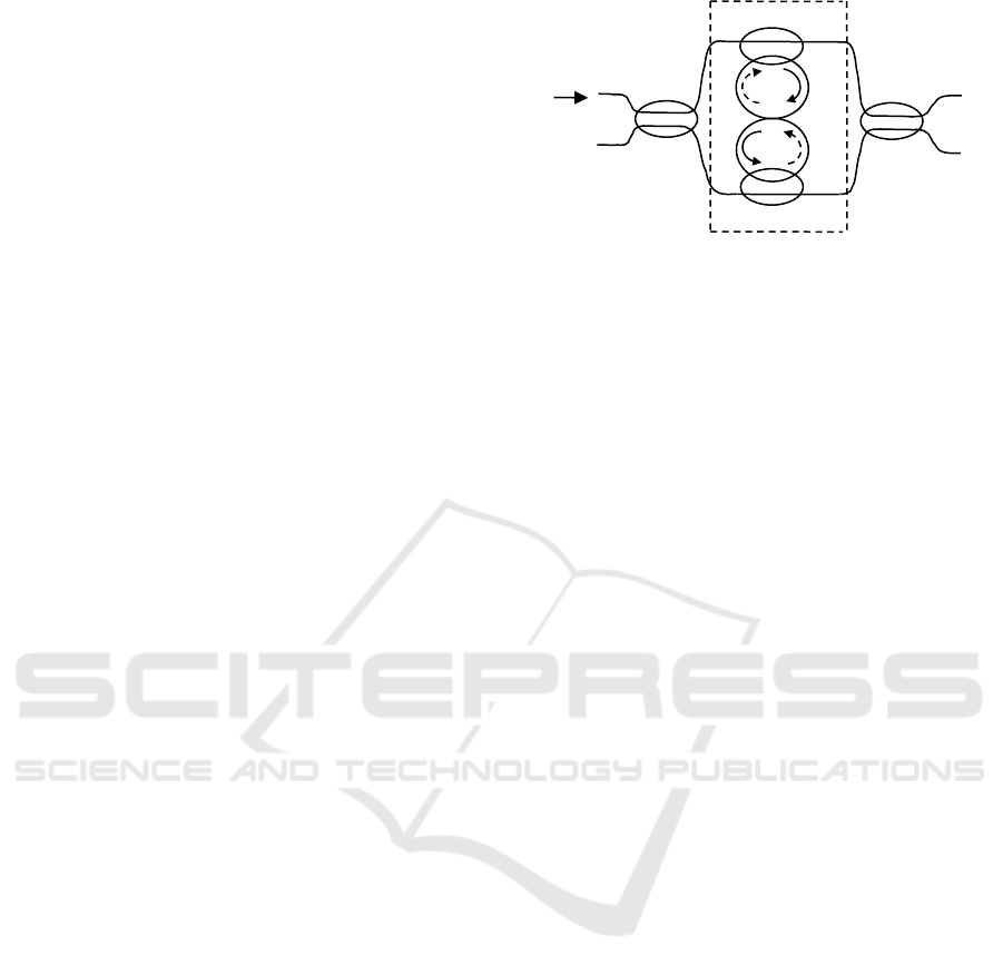
2 STRUCTURAL PRINCIPLE
The 8-shaped fiber ring resonator with self-feedback
loop is shown by the dashed box in Figure 1, which
is consists of two 2 × 2 fiber couplers DC1 and DC2,
which are linked together by fiber arm
1
l
and
2
l
.
There is no cross connection point between fiber
1
l
and
2
l
, and the optical signals through
1
l
and
2
l
are
transmitted independently of each other. The lower-
left input port of DC1 and the upper-right output
port of DC2 are connected by
2
l
, and the lower-
right output port of DC1 and the upper-left input
port of DC2 are connected by
1
l
. In this paper, a
novel all-fiber MZI interleaver based on the 8-shape
fiber resonator is shown in Figure 1. It consists of
two 2 × 2 fiber couplers (DC0, DC3) and an 8-
shaped fiber ring resonator. The coupler DC0 and
the 8-shaped fiber ring resonator are connected by
optical fiber
3
l
and
4
l
, the 8-shaped fiber ring
resonator and the coupler DC3 are connected by
optical fiber
5
l
and
6
l
, and they form a two-stage
cascaded MZI interleaver.
Figure 1: Structure of interleaver based on 8-shaped fiber
ring resonator.
The 8-shaped fiber ring resonator shown in the
dashed line of Figure 1 has two input ports and two
output ports. Set input light fields be
inin
EE
21
, and
output light fields be
outout
EE
21
. By using the
principle of fiber transmission and matrix transfer
theory, the relationship between the input light fields
and the output light fields can be derived as follows
in Equation 1.
in
in
out
out
E
E
FF
FF
E
E
2
1
43
21
2
1
(1)
Where
))(exp(coscos1
212121
lljkkM
;
)))(exp(cos(cos
212211
1
1
lljkkMF
;
)exp(sinsin
2212
1
2
ljkkMF
;
)exp(sinsin
1211
1
3
ljkkMF
;
)))(exp(cos(cos
211212
1
4
lljkkMF
.
1
k
and
2
k
represent the coupling coefficient of DC1
and DC2.
is the propagation constant in the fiber,
and
/2
eff
n
,
eff
n
is the refractive index of the
fiber,
is the wavelength.
)exp(
11
l
and
)exp(
22
l
(
is the transmission loss
coefficient) are the normalized losses of light signals
through fibers
1
l
and
2
l
respectively.
Figure 1 shows that the input light field
in
E
is
only through port 1 of the coupler DC0, and the
optical signal is transmitted to the 8-shaped fiber
ring resonator via the interference arms
3
l
and
4
l
,
and then transmitted to the coupler DC3 via the
interference arms
5
l
and
6
l
. Finally, the output light
fields from the A and B ports of the coupler DC3.
DC0
DC1
DC2
2
l
2
l
1
l
1
l
3
l
4
l
DC3
5
l
6
l
2
E
in
1
A
B
CTISC 2019 - International Conference on Advances in Computer Technology, Information Science and Communications
72

Set
0
k
and
3
k
represent the coupling coefficient of
DC0 and DC3, neglecting the transmission loss of
fiber couplers, and the expression of the output light
fields
A
E
and
B
E
can be derived as Equation 2.
512
3
34
6
3
0
4
exp( ) 0
0 exp( )
exp( ) 0
0 exp( )
0
A
B
in
jl
F
FE
S
F
FEjl
jl
E
S
jl
(2)
Where
)3,0(
cossin
sincos
i
kkj
kjk
S
ii
ii
i
By the light intensity formula
*
E
E
P
, set the
device interference arms
41
ll
,
12
3ll
,
43
2ll
,
45
2ll
,
46
ll
,
lll
34
,
l
(transmission phase delay of interference arm), if the
transmission loss of 8-shaped fiber ring resonator is
ignored,
A
P
and
B
P
are normalized output intensity
which are shown in Equation 3.
)4sin2sin6cos
4cos2cos
4sin2sin6cos
4cos2cos(
543
210
1
543
210
1
bbb
bbbDP
aaa
aaaDP
B
A
(
)
(3)
Where
3
2
0
2
3
2
0
2
sinsincoscos kkkkA
;
3
2
0
2
3
2
0
2
sincoscossin kkkkB
;
3300
cossincossin kkkkC
;
4coscoscos2coscos1
212
2
1
2
kkkkD
;
2
2
1
2
2
2
1
2
0
sinsin)cos(cos kkBkkAa
;
)sincos2cossin(sin2
211
2
2
2
1
2
1
kkkkkCa
;
212
coscos2 kkAa
;
2
2
3
cos2 kCa
;
)sin)(sinsin(cos
cossinsinsin2
213
2
3
2
00214
kkkk
kkkka
;
)sin(cos
cossincossinsin2
0
2
0
2
332215
kk
kkkkka
;
2
2
1
2
2
2
1
2
0
sinsin)cos(cos kkAkkBb
;
11
ab
;
212
coscos2 kkBb
;
33
ab
;
44
ab
;
55
ab
.
For all-fiber MZI interleaver, the basic
requirement is that the two output channels should
have the same output waveform. That is, the
requirement is satisfied Equation 4.
)()2/(
AB
PP
(4)
Analysis Equation 3 can be found that the basic
condition for satisfying Equation 4 is that the
coefficients in
)(
A
P
and
)(
B
P
satisfy
00
ba
and
22
ba
, from which can determine
4/
30
kk
. That is, DC0 and DC3 are designed
as 3dB couplers. When
4/
30
kk
, the
Equation 3 will be simplified to Equation 5.
Q
kP
P
Q
kP
P
B
A
2
6coscos2cos
2
1
2
6coscos2cos
2
1
2
2
2
2
(5)
Where
2
2
1
2
1
2
21
sinsincoscoscos2 kkkkkP
;
4coscoscos2coscos1
212
2
1
2
kkkkQ
.
Obviously, Equation 5 satisfies both Equation 4
and
1)()(
BA
PP
. In addition, it can be seen
from Equation 3 that
A
P
and
B
P
contain coupling
coefficients of the fiber couplers and transmission
phase delay of the interference arm. The former
determines waveform of the output spectrum, and
the latter decides cycle of the output spectrum.
When the coupling coefficients and the fiber
interference arm length select appropriate values, the
device can realize comb and equivalent bandwidth
of output spectrum. When the input light field
in
E
is
through port 1 or port 2 of DC0, because the optical
paths of the interfering optical signals are not much
different, and the output spectrum of the device is
the same.
3 NUMERICAL SIMULATION
In numerical simulation analysis, application
optimization algorithm, selecting the parameters
40/
1
k
,
8.2/
2
k
,
4/
30
kk
,
mml 1
,
nm1550
0
,
457.1
eff
n
, the
Design Analysis of a Novel All-Fiber Mach-Zehnder Interferometer Interleaver
73
simulation result is shown in Figure 2(In the
following figure,
A
P
is the solid line,
B
P
is the
dotted line.). It can be seen from Figure 2 that
interleaver output spectrum of the port A and port B
are the same two groups of equal bandwidth periodic
spectral lines, and each odd (even) group frequency
interval is 100GHz, and calculated 0.5dB passband
bandwidth is 43.2GHz, the 25dB stopband
bandwidth is 32.3GHz. The flat-top appears in the
output spectrum, which can offset the negative
influence of channel wavelength drift. Figure 2
shows, through the phase adjustment of the fiber
ring resonator, the output spectrum produces a steep
edge, and forming a similar to a rectangle wave,
which is greatly improved compared to the cosine
output spectrum of the conventional MZI
interleaver.
Figure 2: Normalized intensity of all-fiber MZI interleaver
with
4/,8.2/,40/
3021
kkkk
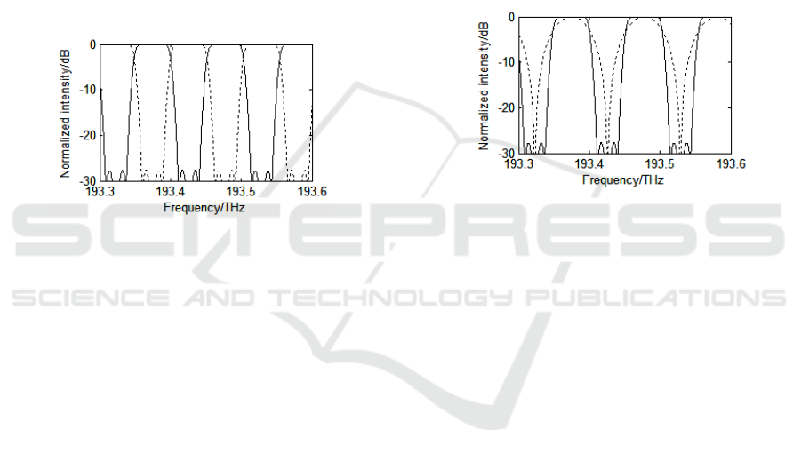
Figure 3 is a comparison of the 0.5dB passband
bandwidth and the 25dB stopband bandwidth
between conventional MZI interleaver and improved
MZI interleaver based on fiber ring resonator. The
dashed lines and solid lines represent the output
spectrum of conventional interleaver and improved
interleaver. By calculation, the 0.5dB passband
bandwidths respectively are 21.3GHz and 43.2GHz.
The 0.5dB passband bandwidth of improved
interleaver accounts for 86.4% of the 50GHz
frequency interval, and the 0.5dB passband
bandwidth of conventional interleaver accounts for
42.6% of the 50GHz frequency interval, the 0.5dB
passband bandwidth of improved interleaver is
significantly improved. The 25dB stopband
bandwidths of the two interleavers respectively are
3.6GHz and 32.3GHz. The 25dB stopband
bandwidth of improved interleaver accounts for
64.6% of the 50GHz frequency interval, and the
25dB stopband bandwidth of conventional
interleaver accounts for 7.2% of the 50GHz
frequency interval, the 25dB stopband bandwidth of
improved interleaver is significantly broadened.
These indicate that the output spectrum of the MZI
interleaver based on the 8-shaped fiber ring
resonator has good rectangle wave characteristics. In
addition, the 25dB stopband bandwidth of the two-
stage cascade MZI interleaver designed in paper
(Shaw Wei Kok, 2003) is about 15.8GHz,
accounting for 31.6% of 50GHz frequency interval;
The 25dB stopband bandwidth of MZI interleaver
designed in paper(H.W. Lu, 2012) is about
18.4GHz, accounting for 36.8% of 50GHz frequency
interval; The 25dB stopband bandwidth of MZI
interleaver designed in paper(H.W. Lu, 2006) is
about 24GHz, accounting for 48% of 50GHz
frequency interval; Compared with three interleavers
above, the output spectrum of the novel MZI
interleaver designed in this paper is more close to
rectangle wave, and the 0.5dB passband and 25dB
stopband are wider than others.
Figure 3: The comparison between conventional MZI
interleaver and improved MZI interleaver
4 ANALYSIS DISCUSSION
4.1 Influence of Coupler Coefficient on
the Interleaver Response
It can be seen from Equation 5 that when the
couplers DC0 and DC3 are 3dB couplers, the length
differences of interference arms are constant, and the
output spectrum mainly depends on coupling
coefficients of DC1 and DC2. The coupling
coefficients
1
k
and
2
k
will determine the size of the
channel segregation and the shape of the output
spectrum. In addition, the influence of the
experimental environment and the manufacturing
process, the coupling coefficient of the couplers are
deviated from the ideal values, and the deviation of
1
k
and
2
k
directly affect the split ratio of the
couplers. Therefore, it is necessary to discuss the
influence of the deviation of the coupling coefficient
on the interleaver output spectrum.
Set
%15
11
kk
and
%5
22
kk
as the
deviations of the coupling coefficients, other
parameters remain unchanged, the numerical
CTISC 2019 - International Conference on Advances in Computer Technology, Information Science and Communications
74
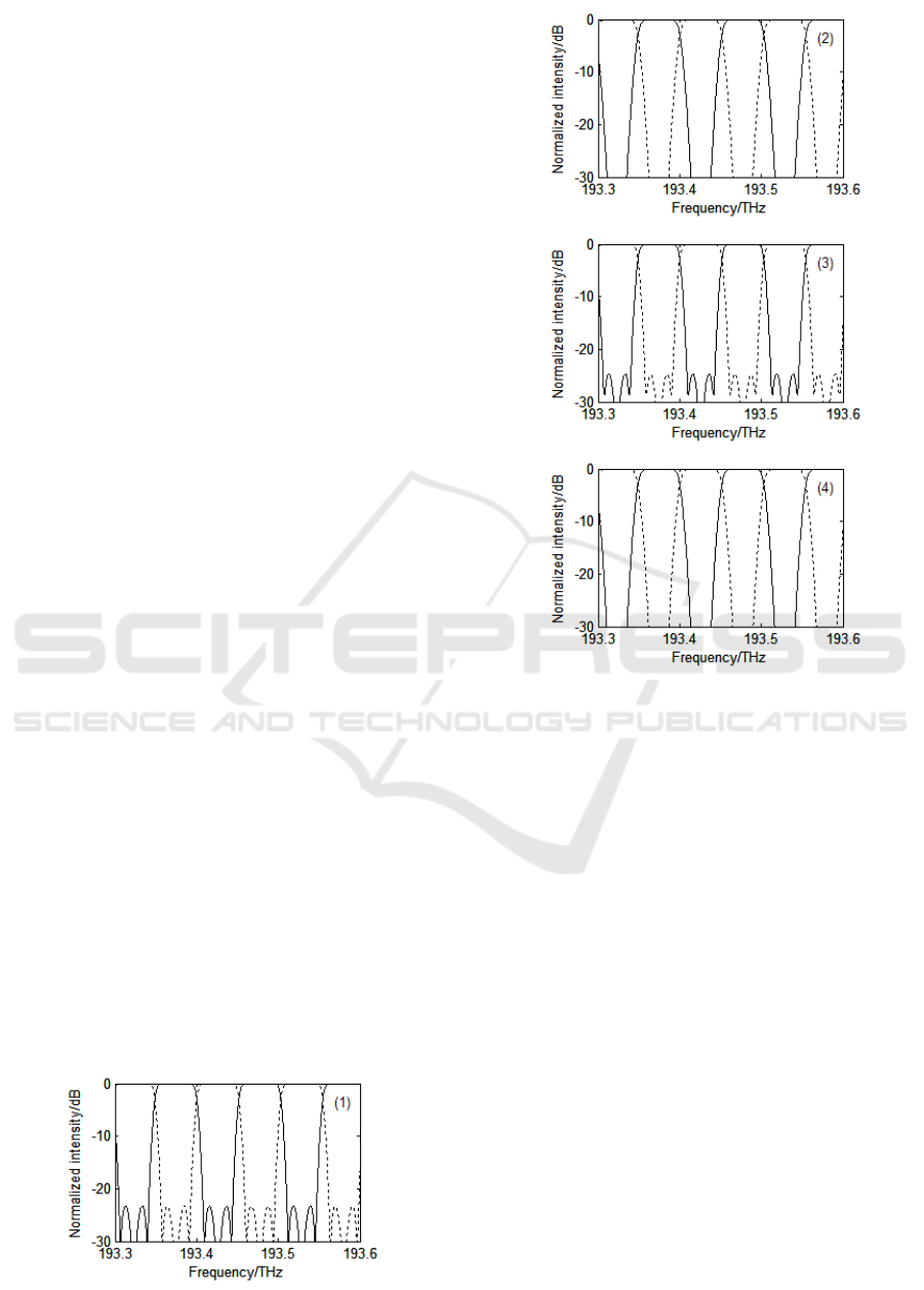
simulation results show the deviation in range. If
only changes
1
k or
2
k , the 0.5dB passband
bandwidth and the 25dB stopband bandwidth of the
output spectrum do not change much, and the output
spectrum shape remains basically unchanged. If the
coupling coefficients of DC1 and DC2 reduce
simultaneously, the 0.5dB passband bandwidth will
change the range of 43.2~44.7GHz, and the 25dB
stopband bandwidth will change the range of
32.3~35.7GHz. Figure 4(1) is the output spectrum of
interleaver with
111
kkk
and
222
kkk
,
its passband bandwidth and stopband bandwidth
compared with best value increase slightly, but the
side-lobe level also increase(In the following figure,
A
P
is the solid line;
B
P
is the dotted line.). If the
coupling coefficients of DC1 and DC2 increase
simultaneously, the 0.5dB passband bandwidth will
change the range of 41.7~43.2 GHz, and the 25dB
stopband bandwidth will change the range of
28.0~32.3GHz. Figure 4(2) is the output spectrum of
interleaver with
111
kkk
and
222
kkk
,
its passband bandwidth and stopband bandwidth
compared with best value decrease slightly, and its
side-lobe level decrease. If the coupling coefficients
of DC1 increases and the coupling coefficients of
DC2 reduces, the 0.5dB passband bandwidth will
change the range of 43.2~44.3GHz, and the 25dB
stopband bandwidth will change the range of
32.3~35.1GHz. Figure 4(3) is the output spectrum of
interleaver with
111
kkk
and
222
kkk
,
its passband bandwidth and stopband bandwidth
compared with best value increase slightly, but the
side-lobe level also increase. If the coupling
coefficients of DC1 reduces and the coupling
coefficients of DC2 increases, the 0.5dB passband
bandwidth will change the range of 41.8~43.2GHz,
and the 25dB stopband bandwidth will change the
range of 28.4~32.3GHz. Figure 4(4) is the output
spectrum of interleaver with
111
kkk
and
222
kkk , its passband bandwidth and
stopband bandwidth compared with best value
decrease slightly, and its side-lobe level decrease.
Figure 4: Normalized intensity of all-fiber MZI Interleaver
with
4/
30
kk
,
222111
,)1( kkkkkk
,
111
)2( kkk
,
222
kkk
,
111
)3( kkk
,
222
kkk
,
222111
,)4( kkkkkk
It can be known from the calculation that if the
segregation of the adjacent channel is to be above
25dB, the deviation of
1
k
is kept at
%20
, and the
deviation of
2
k is maintained at
%8
. Moreover,
the analysis found that increasing the coupling
coefficient of DC2, the coupling coefficient of DC1
increases or reduces, the 0.5dB passband bandwidth
and the 25dB stopband bandwidth decreases, and the
side-lobe level decreases. Reducing the coupling
coefficient of DC2, the coupling coefficient of DC1
increases or reduces, and the 0.5dB passband
bandwidth and the 25dB stopband bandwidth
increases, and the side-lobe level increases. It can be
seen that the shape of the output spectrum mainly
depends on coupling coefficient of DC2, and try to
keep
2
k
within the deviation range.
By analyzing the interleaver output spectrum
performance, it can be concluded that the couplers
DC0 and DC3 are 3dB couplers, the length
Design Analysis of a Novel All-Fiber Mach-Zehnder Interferometer Interleaver
75
differences of interference arms are constant, when
slightly deviation of the coupling coefficients of
DC1 and DC2 exists, the 0.5dB passband and the
25dB stopband will show deviation, but the change
is not obvious, and the channel segregation can be
above 25dB, which can satisfy the actual needs. The
device has a certain ability to resist the deviation,
which will reduce the difficulties in fabricating it.
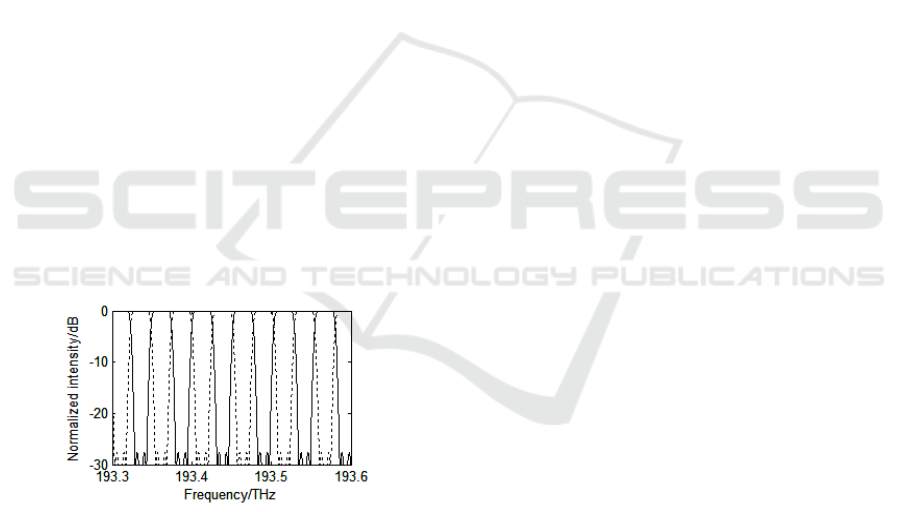
4.2 Influence of Fiber Interference
Arm the Interleaver Response
In the process of numerical simulation, when the
ratio of the length difference of the three pairs of
interference arms is kept constant, and the length
difference is adjusted, the frequency interval of the
output spectrum is adjusted accordingly. That is, if
the length difference relationship of each
interference arm is constant, the length difference
increases, the frequency interval of the output
spectrum will be narrowed, the length difference
reduces, and the frequency interval will be widened.
When the coupling coefficients of the couplers are
constant, the length difference of fiber interference
arm is
mml 2
, the output spectrum is shown in
Figure 5, and each odd (even) group frequency
interval is changed from 100GHz to 50GHz, the
wavelength interval is 0.4nm. By changing the
length difference, the frequency interval is changed,
which has certain reference value in the practical
application of the device.
Figue 5: Normalized intensity of all-fiber MZI Interleaver
with
mml 2
The derivation process found that within a given
wavelength range, the periodicity of the output
spectrum is determined by the transmission phase
delay of interference arm (
l
). The range of
spectrum (
) can be derived as follows in
Equation 6.
)/()/(
2
1212
lnln
effeff
(6)
5 CONCLUSIONS
A novel structure of all-fiber interleaver is proposed
in this paper. Using an 8-shaped fiber ring resonator
feedback loop to introduce phase adjustment into the
optical signal, the interleaver has a wider 0.5dB
passband bandwidth and 25dB stopband bandwidth,
and the rejection in stopband and the roll-off in
transition band are improved remarkably. Through
theoretical analysis and numerical simulation, the
structural parameters of the output spectrum with
flat top and approximate rectangular wave are
obtained. The output spectrum is not sensitive to the
deviation of the coupling coefficient of the fiber
coupler, and the device has a certain ability to resist
the deviation and reduces the difficulty of its
fabrication. Keep the ratio of the length difference of
the interference arm unchanged, by changing the
length difference, the frequency interval is changed,
which has certain reference value in the practical
application of the device. The study may provide a
new idea and method for all-fiber passive
components.
ACKNOWLEDGEMENTS
This study is funded by the Natural Science
Foundation of Gansu Province of China
(No.1310RJZA075), it is gratefully acknowledged.
REFERENCES
Shaw Wei Kok, Ying Zhang, Changyun Wen and Yeng
Chai Soh. Design of all-fiber optical interleavers with
a given specification on passband ripples. Optics
Communications, 226:241, 2003.
H.W. Lu, Y. Lu, H.L. Pu and G.W. Luo. Improved designs
of all-fiber 3×3 interleaver with flat-topped passband.
Acta Optica Sinica. 35:0206003, 2015.
B.G. Zhang and H. Xiao. Study of an all-fiber interleaver
with flattop wavelength response. Optical
Engineering, 55:046118, 2016.
G. Zhou, C.L. Zhao, Y.L. Huang, S.Q. Yang, H.Y. Meng,
Q.D. Zhao et al.. Improvement of the capability of
nonsymmetrical Mach- Zehnder interferomtric
interleaver using fiber loop. Acta Optica Sinica, 22:
702, 2002.
W.B. Li and J.Q. Sun. Analysis of Characteristics of the
Interleaver Based on a Double-coupler Resonator.
Chinese J. Laser, 35:1191, 2008.
X.W. Dong, L. Pei, O. Xu, S.H. Lu, S.C. Feng, R.F. Zhao
et al.. Study of interleaver based on ring resonator
assisted Mach-Zehnder interferometer. Acta Optica
Sinica, 28:638, 2008.
CTISC 2019 - International Conference on Advances in Computer Technology, Information Science and Communications
76

H.W. Lu, K.J. Wu, Y. Wei, C.L. Wang, Z.J. Jiang and
G.W. Luo. Study of a novel symmetrical interleaver
based on ring resonator assisted Mach-Zehnder
interferometer. Acta Optica Sinica, 32:1106005,
2012.
H.W. Lu, B.G. Zhang, M.Z. Li and G.W. Luo. A novel
all-fiber optical interleaver with flat-top passband.
IEEE Photon. Technol. Lett., 18:1469, 2006.
Design Analysis of a Novel All-Fiber Mach-Zehnder Interferometer Interleaver
77
