
Design and Implementation of Modular Honeynet System Based on
SDN
Yan Li
1
, Bin Wu
1
1
School of Cyberspace security, Beijing University of Posts and Telecommunications, No.10 Xitucheng Road, Beijing,
China
Keywords: Honeynet, Modular System, SDN, Attack Tree.
Abstract: Traditional honeynets cannot dynamically migrate traffic. The flexibility of SDN can solve this problem. At
the same time, the traditional honeynets have the disadvantages of complicated alarm logs and inability to
carry out targeted analysis, and lacks protection for the honeypot. It is easy to completely destroy the
honeypot and make it a jumper for the attacker to launch the next attack on the intranet. This paper proposes
a modular honeynet system based on SDN, which can respond to the scanning probe-exploit-worm injected
attack chain, reducing the complexity of the alarm log and improving the efficiency of the researchers in
analyzing attacks. Also, a honeypot switching strategy based on the detection of the attack tree phase is
proposed in the module of vulnerability response, which can delay the attacker's attack progress and reduces
the risk of the honeypot. The experiment also verified the feasibility of the modular system.
1 INTRODUCTION
The Internet has become an indispensable part
of people's daily lives and network security has
become an issue of increasing concern. The
defenders proposed the honeynet technology
(Jianwei Zhuge, 2013) as a mean of active defense
in a passive situation. In terms of passive defense,
active defense emphasizes that it can promptly warn
before the intrusion causes damage to the system,
avoiding and diverting the attack risk faced by the
system. In this paper, the Software Defined Network
(SDN) technology and honeypot technology are
deeply studied.
The honeynet is a hacker trap network system
consisting of several honeypots that can seduce
attackers and collect attack data. The honeynet
stores false sensitive data and does not provide
normal services. It is pre-arranged in the honeypot.
The vulnerability and monitoring system can seduce
the attacker and monitor and record the attack
behavior, so that the defensive party can restore and
trace the attack behavior, so as to better defend the
service network where the real host is located.
However, traditional honeynets are mostly based on
traditional network devices as honeynet gateways
(More Asit, 2013), which achieve the purpose of
traffic migration through program burning. This
method is not flexible enough and has security risks.
On the other hand, the traditional honeynet responds
to the attacker's overall attack behavior, which often
causes the recorded attack data to be too
cumbersome and confusing. It is difficult for
defenders to judge the impact of each attacker's
attack, which is not easy to analyze the attack
behavior.
To solve the problem that the traditional
honeynet alarm log has high complexity and lacks
protection for honeypots, this paper combines
honeynet and SDN technology, and uses SDN
flexible and convenient features to innovatively
propose a modular honeynet system based on SDN.
The attack behavior of the attacker is divided into
three stages: topology scanning-exploiting-worm
injecting. The three modules respond to the three-
stage attack respectively. It reduced the level of
alarm confounding, which is convenient for
researchers to analyze the attack in stages. Also, this
paper proposed a honeypot switching strategy based
on the attack tree to cut the exploit behavior and
reduce the success rate of the attacker, so as to
prevent the honeypot from being completely
attacked by the attacker and become a jumper for
attacking the net. It solved the problem of traditional
honeynet lack of protection for honeypots.
Li, Y. and Wu, B.
Design and Implementation of Modular Honeynet System Based on SDN.
DOI: 10.5220/0008098102030212
In Proceedings of the International Conference on Advances in Computer Technology, Information Science and Communications (CTISC 2019), pages 203-212
ISBN: 978-989-758-357-5
Copyright
c
2019 by SCITEPRESS – Science and Technology Publications, Lda. All rights reserved
203

2 RELATED RESEARCH
2.1 Related Research on SDN
SDN technology is an innovative network
architecture proposed by the Clean State group of
Stanford University (Nunes, B., 2014). Different
from OSI seven-layer model, the SDN architecture
consists of the infrastructure layer, the control layer
and the application layer, as shown in Figure 1. In
the SDN architecture, the infrastructure layer is
responsible for data processing, forwarding, and
state collection. The control layer is responsible for
sending flow tables to the infrastructure layer
devices to achieve fast processing of matching flow
table traffic. The application layer includes various
services and applications. The application written by
the SDN controller is running on this layer to
implement network business functions (McKeown,
N., 2008).
Network
equipment
Network
equipment
Network
equipment
Network
equipment
Network
equipment
Infrastructure Layer
Control Layer
SDN control
software
Net Service
Net Service
Net Service
Control/Data Plane Interface e.g. OpenFlow
Application Layer
Application
Application
Application
API API API
Figure 1: The architecture of SDN.
2.2 Research on Honeynet Based on
SDN
Honeynet is a fake network architecture for
security defense. The proposed honeynet technology
benefits from the active defense theory proposed by
the defender in response to the long-term passive
situation of the attack. In the traditional honey
network architecture, the traffic forwarding function
is implemented by HoneyWall. The honey network
is connected to the external network, the internal
network, and the management server or IDS device.
However, such a deployment method requires a lot
of manual operation and high-performance hardware.
And the software running on the honey wall needs to
be constantly updated and re-programmed to meet
the different needs of the defender, which greatly
restricts the use of the honey wall.
With the introduction and development of SDN
technology, many researchers have noticed the
flexibility, programmable, and virtualized features of
SDN technology. Therefore, many SDN-based
honey network architecture solutions have emerged.
Wonkyu Han (2016) proposed the SDN-based
smart honeynet HoneyMix, which filters the
fingerprint information through controller
programming, making the honeypot more difficult to
be detected by the attacker and broadcasting the
connection request of the attack traffic to other
honeypots in the honeynet. Select the honeypot that
the attacker is most interested in to respond, to
achieve better effect of attracting attackers and
prolong the connection time of the attacker.
Stefan Achleitner (2017) designed an SDN
honeynet system for intranet scanning spoofing,
which forwards all traffic of the intranet to the RDS
(Reconnaissance Deceiving Server) via SDN. When
the scanning behavior is detected, the fake network
topology information is generated by the RDS.
Return to the attacker and extend the scan time
through the delay and queuing strategy to find the
location of the infected host before the attacker
completes the scan.
Wenjun Fan (2017) believed that the current
traffic redirection mechanism, especially the TCP
connection switching, is not hidden and easy to be
discovered by attackers. Therefore, an SDN-based
hybrid honeypot system network data controller is
proposed, which is forged. The serial number of the
current TCP session implements the secret switching
of TCP, and implements filtering of traffic based on
the alarm function of Snort.
Qiuchen Ren (2018) proposed an SDN honey
network system based on multi-controller
equalization strategy. The system can simulate
dynamic routing protocols, routing functions, and
virtualize the network topology to achieve the
purpose of deceiving attackers. At the same time, the
spectral clustering algorithm is improved, and the
functions of controller load balancing and flow
control are optimized.
2.3 Research on Attack Tree Model
Bruce Schneier (1999) first proposed the attack
tree model to describe the attack in 1999. The root
node of the tree represents the final intrusion target,
and the child node represents the attack method
adopted by the parent node. The relationships
between child nodes are "or" and "and", as shown in
Figure 2:
CTISC 2019 - International Conference on Advances in Computer Technology, Information Science and Communications
204

OR
AND
Figure 2: Relationship between child nodes
An "or" relationship means that the completion
of any child node means the completion of the
parent node, and the "and" relationship means that
all child nodes have been completed to indicate that
the parent node is completed.
The generation of the attack tree is a process of
reasoning backwards from the root node. The
specific steps are as follows:
(1) Determine the ultimate goal of the attack,
which is the root node of the attack tree.
(2) Using the root node as a starting point,
matching the collected attack information for the
target with the attack rule in the attack tool library,
and if it matches, generating a new child node.
(3) Each node is regarded as a sub-goal, and a
new node is generated by the attack method and rule
matching the child node in the tool library as a child
node of the current sub-goal.
(4) Repeat the above steps until the child nodes
can no longer be split.
3 SYSTEM DESIGN
3.1 System Architecture
Attacker Router
OpenFlow
S2
Topology
generator
Strategy
center
Flow table
generator
Controller
OpenFlow
S3
Web Server SQL Server FTP Server
Web Hp SQL Hp FTP Hp
OpenFlow
S4
Mirror-
Honeypot
OpenFlow
S5
Web
Honeypot
Cluster
SQL
Honeypot
Cluster
FTP
Honeypot
Cluster
Worm trap
vSphere
OpenFlow
S1
Business
network
Traffic collector
Figure 3: System structure.
The system structure is shown as Figure 3. The
controller (including topology generator, policy
center and flow table generator) is responsible for
the response to the topology scan. The honeypot
cluster is responsible for the response of the exploit
attack, and the worm trap is responsible for the
response of the worm impact. The system contains 5
OpenFlow switches, which are respectively recorded
as S1~S5. S1 acts as a master switch and connects
directly to the external network. The controller
consists of three modules, namely the topology
generator, which is responsible for generating the
virtual topology of the response scan according to
the configuration file. The policy center is
responsible for identifying malicious traffic and
worms. The flow table generator is responsible for
generating the switch flow table and delivering it to
the switch. The S2 switch is connected to the service
network, and normal traffic is accessed to the service
network through the S2 switch. S2 is also connected
to a traffic collector. All traffic of S2 is copied by
the traffic collector. The traffic collector analyzes
the traffic in the domain. If there is any malicious
traffic or worm virus that is under-reported, it will
feedback to the policy center through S2. The policy
center updates its own rule base to match the newly
discovered malicious traffic. The S4 switch is
connected to the mirrored honeypot. The physical
properties of the mirrored honeypot are the same as
those of the service network. The service network is
cloned. Each service network host has its own
mirrored honeypot. The purpose of setting up a
mirror honeypot is to attack the implanted third step,
the worm or Trojan that the attacker wants to
implant into the network, which will be directed to
the mirror honeypot, because the mirror honeypot is
for the business. The cloning of the network is very
similar to the real network environment, so the
behavior of the worm or the Trojan can be observed
in the mirror honeypot to infer the action and
destructive power of the virus in the real network
environment, so that the researchers can better
Targeted defense. The S5 switch connects honeypots
managed by vSphere. These honeypots are classified
according to the types of attacks they can respond to
and are used to respond to the second step of the
attack, namely exploit exploits. For this part of the
honeypot, the "honeypot switching" strategy is
adopted, that is, for the attack of a certain service,
the attacking step is hierarchically split by the
attacking tree, and then the honeypots in the same
cluster respond to different levels of attacks. When
the attack is found to enter the next stage, the attack
traffic is imported into another honeypot in the same
Design and Implementation of Modular Honeynet System Based on SDN
205
cluster, so that the attacker's previous attack will be
invalid. In this way, the attacker's attack progress is
delayed, and the honeypot is broken to be used as a
springboard to continue the attack on the intranet.
On the other hand, the attacker's attack time can be
prolonged, and the attack behavior can be more
easily collected. More attack data. In addition,
considering that in the process of honeypot
switching, since the response attacks are different
hosts before and after the handover, the sequence
number may be different in the attacked TCP
connection. For this case, the current TCP packet
sequence number is copied. The method in the next
stage of the attack, so that the switch is not
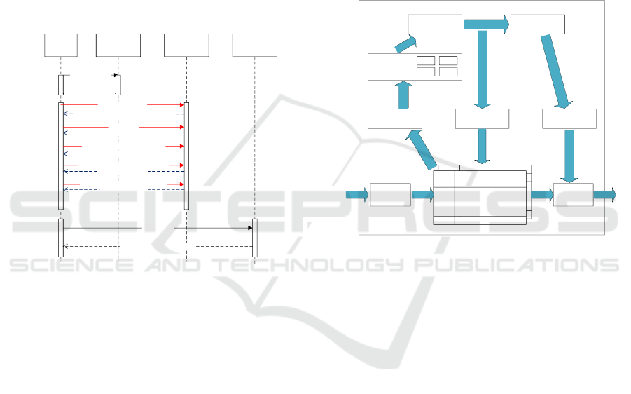
perceived by the attacker. A typical timing diagram
is as follows:
Attacker
Topology
simulation
module
Exploit
module
Worm
capture
module
Topology scanning
Return virtual topology
Vulnerability scanning
Modify the destination address
Return the honeypot vulnerability information.
PhaseⅠattack
Honeypot A responses
PhaseⅠfinished, begin PhaseⅡ attack
Switch to Honeypot B
Attack failed. Restart Phase Ⅰ&Ⅱ attack
Honeypot B responses
Phase Ⅱ finished, begin Phase Ⅲ attack
Switch to Honeypot C
Worm implant
Mirror-Honeypot capture the worm
Figure 4: Attack timing diagram.
The attacker first performs topology scan
detection on the network, and the topology
simulation module generates a corresponding virtual
topology according to the previously issued
topology file and presents it to the attacker. Then,
the attacker performs a vulnerability scan on the
terminal node in the collected topology. Since the IP
address in the virtual topology is forged, the virtual
IP needs to be reverse mapped to the honeypot IP,
and the honeypot responds to the vulnerability of the
attacker’s scanning. After finding out the
vulnerabilities on the honeypot, the attacker exploits
the vulnerability to attack. According to the stage of
the attack tree's vulnerability attack, each time the
attack reaches a new stage, a new honeypot is
switched to respond to the attack. Some attacks rely
on the results of the previous attack. Such a switch
causes the attacker to abandon the attack and needs
to restart the attack. The multiple switch will cause
the attacker to slow down and give up the attack. For
the honeypot, both the attacker's attack information
is collected and the self-protection effect is achieved.
When the attack progresses to the worm implant, the
worm is identified by the controller's policy center,
and is directed to the mirrored honeypot for worm
capture by sending the flow table. Because the
mirror-honeypot is a clone of the business. With the
height simulation of the web host, the researchers
can observe the behavior of the worm in the mirror
honeypot to assess its destructive power in the real
environment.
3.2 Topology Simulation Module
Receiver
Flow 1
Flow 2
Flow n
Flow 1
Flow 2
Flow n
Sender
Buffer
Configuration
information reading
Generating
information
calculation
Packet generatorFlow table generator
ARP ICMP
UDP TCP
Packet parser
Packet-in
message
Packet-out
message
Flow-mod
message
Figure 5: Block diagram of Topology simulation module.
The topology simulation module is shown in
the Figure 5. For the network traffic received by the
switch, the switch flow table is matched first, and
the matched data packets are directly forwarded
according to the rules specified in the flow table. If
the matching fails, the packet-in message is used.
The form is sent to the controller's packet buffer.
The controller first parses the data packet, and
according to the protocol of the data packet, it is
processed by different modules. Then the
configuration file is read to obtain the structure of
the network topology to be generated and the
information such as the IP address and the MAC
address of each node is used to calculate the packet
information based on the information. Finally packet
generator generates a packet to reply the requester in
the form of a Packet-out message.
If the traffic that does not need to be responded
to by the topology simulation module, for example,
the traffic that is used for the first time to access the
normal service, the flow table generator generates a
response flow table and sends it to the switch to
facilitate fast matching and processing of subsequent
traffic.
CTISC 2019 - International Conference on Advances in Computer Technology, Information Science and Communications
206

To complete the response to the network
topology scan, mainly to spoof ping and traceroute
(Windows system is tracert) command detection,
these two commands mainly rely on ICMP protocol,
and the premise of ICMP protocol is that the attacker
knows the physical address of the destination host,
That is, the ARP protocol. As long as you can
simulate the ARP and ICMP protocols, you can
respond to basic ping and traceroute probes. The
principle of topology simulation is described below:
3.2.1 ARP Simulation
The ARP (Address Resolution Protocol)
protocol is used to obtain the physical address based
on the IP address. The OpenFlow switch is a Layer 2
device. It does not have an IP address and cannot
answer ARP requests. The system uses the ARP
response method from the controller. When the
controller receives the ARP request, it searches for
the MAC address of the corresponding IP according
to the content of the configuration file, and
constructs a response packet according to this, and
returns it to the requesting party.
3.2.2 ICMP Simulation
The Internet Control Message Protocol (ICMP)
protocol is often used to test network connectivity.
Scanning the network topology is based on ICMP.
ICMP is generally used for two commands: ping and
traceroute. When the controller receives the ping
request, the configuration file is read, and the
connectivity between the target host and the request
source and the hop count are determined according
to the network topology defined by the configuration
file, and the response packet is constructed
according to the configuration, and returned to the
requesting party. The principle of detecting the
network topology by using traceroute is that the
attacker first sends a packet with a TTL of 1 to the
destination. When the first router on the path
receives it, the TTL is decremented by 1. At this
time, the TTL is 0. The router will discard the packet
and return a Time Exceed message. Upon receiving
the message, the attacker knows that there is a router
on the path, and then sends a packet with a TTL of 2
to probe the second route. Repeat the above actions
until the data packet is sent to the destination host.
Since the traceroute command generally sends UDP
packets, the destination port is 33434~33534. The
general application will not use this range of ports,
and the host will reply to ICMP after receiving it.
Port Unreachable message, after the attacker
receives it, it can judge that the destination has
arrived. The traceroute command can send UDP,
TCP, and ICMP packets separately using different
parameters. The system processes all three
traceroute requests and can respond to traceroute
probes under different parameters.
3.3 Exploit Module
In the exploit response module, we used a
honeypot switching strategy based on attack tree
phase detection. The attack that may be suffered is
represented in the form of an attack tree. The attack
is divided into multiple paths. Each path is regarded
as a phase of the attack. The IDS is configured to
detect the alarm rules of each phase. When the IDS
sends the next phase. When the attack is alerted, the
attack as the previous stage is completed. At this
time, the IDS reports the attack information to the
SDN controller, and the controller modifies the flow
table to switch the honeypot traffic that is
communicating with the attacker to another
honeypot, in such a manner that the attacker is in the
previous stage. The attack is invalid, which will
slow down the attack and protect the honeypot.
According to the attack tree generation method,
we created an attack tree model that represents a
general network attack (as shown in the Figure 6).
Due to the variety of actual attacks, it is difficult to
display all attacks on one attack tree. This paper
selects the experimental part. The privilege
escalation attack is detailed and analyzed, and other
forms of attack are similar.
G
0
G
1
G
2
G
3
G
4
G
21
G
22
G
23
G
11
G
12
G
31
G
32
G
33
G
41
G
42
G
43
Figure 6: Normal attack tree.
The main sub-target symbols and meanings are
shown in the Table 1:
Design and Implementation of Modular Honeynet System Based on SDN
207
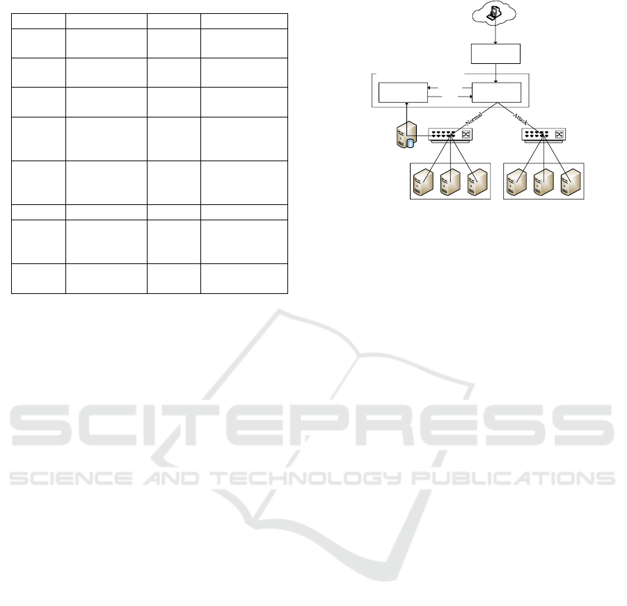
Table 1: Symbol & Meaning of Normal attack tree.
Symbol
Meaning
Symbol
Meaning
G
0
Fully attack
a host
G
22
Configuratio
n error
G
1
Scanning
G
23
Guess weak
password
G
2
Get general
permissions
G
31
Penetration
attack
G
3
Get root
permission
G
32
Known
system
vulnerabilities
G
4
Damage a
host
G
33
Unknown
system
vulnerabilities
G
11
Ping
G
41
DOS
G
12
Other
scanning
tools
G
42
Backdoors
G
21
Vulnerabilit
y attack
G
43
Jumper
3.4 Worm Capture Module
Worm is a malicious program with a high
degree of harm. It can infect the target node and use
the infected node as the source of infection to scan
the network where the node is located, further infect
other nodes in the network, and achieve independent
reproduction and propagation. Once a node in the
network is infected, the entire network may be
compromised by the worm. At present, honeynet is a
main defense method for worms. However, the
traditional honeynet has great limitations on the
behavior of malicious programs such as worms. It is
difficult to study the destructiveness of worms in the
real environment. On the other hand, the detection of
worms relies too much on the feature library and
feature matching algorithms. Detection and feedback
of missing worms. In order to solve these problems,
the system makes full use of the network traffic
control capability of SDN technology, and designs a
worm capture module that can track the entire life
cycle of the worm, including generation,
propagation, propagation, detection and detection
feedback, and simulate the real environment. It is
convenient for researchers to study the behavior and
destructive power of worms in real environments.
The structure of the module is shown as Figure 7:
Attack flow
Matching
engine
Feature
Library
Detection
Result
Business network
Mirror-Honeypot
(Worm trap)
Traffic collector
Feedback
Controller-Policy center
S2 S4
Figure 7: Block diagram of Worm capture module.
The policy center module of the SDN controller
consists of a matching engine and a feature library.
The feature database records the characteristic
information of the known worm, and has the
characteristics of fast detection speed and low false
alarm rate. However, only the known worm can be
detected. The traffic collector can collect and
abnormally detect the traffic in the service domain.
The anomaly detection module uses an anomaly
detection algorithm based on network entropy for
detection (Gu Yu, 2005). The network entropy is
generated by the IP quintuple, and the normal traffic
sample is trained to obtain the maximum network
entropy model of the normal traffic. When the
anomaly detection is performed, the entropy
difference between the network entropy of the traffic
to be detected and the normal traffic is calculated,
and the threshold is about to be detected. The flow
rate is judged to be abnormal. The attacker's
operation of worm implantation is regarded as an
attack flow. The matching engine performs feature
matching on the load field of the traffic, that is,
performs matching search in the feature database. If
the result is matched, the traffic is regarded as
abnormal traffic, and the SDN controller is passed.
The flow table is sent, and the traffic and all
subsequent traffic of the source IP are introduced
into the mirror honeypot through the OpenFlow
switch S4. A mirrored honeypot is a clone of a
service network host. It has the same topology,
physical attributes as the service network.
Researchers can cultivate and observe worms in
mirrored honeypots. If the signature database fails to
match, it is regarded as normal traffic, and traffic is
introduced to the service network providing normal
services through OpenFlow switch S2. All the traffic
in the service network is copied by the traffic
collector. The traffic collector collects the
CTISC 2019 - International Conference on Advances in Computer Technology, Information Science and Communications
208

abnormality of the traffic in the domain based on the
statistics. If the worm is missing, the feature
database is updated to the signature database of the
policy center. To improve the accuracy of feature
detection. In addition, since the worm has infected
the service network node when a missed report is
detected, the researcher is required to manually
remove the worm from the infected node.
4 EXPERIMENT & ANALYSIS
4.1 Environment
The environment of experiment is shown as
Figure 8 and Table 2. Use one server to run SDN
application layer software and three servers to
simulate real business network host, use one server
to accommodate honeypot cluster and run three
honeypots to simulate exploit module. We manage
them through vSphere. Another server was used for
the worm capture experiment.
Attacker
Router
OpenFlow
S1
Controller
OpenFlow
S2
OpenFlow
S3
OpenFlow
S4
Worn trap
Honeypot
cluster
Web Server
FTP Server
DB Server
Figure 8: Environment of experiment.
Table 2: Equipment model and configuration.
Name
System
IP Address
Note
Controller
Ubuntu
16.04
192.168.8.8
Run SDN
application
OpenFlow
Switch
S1~S4
OpenWRT
14.07
-
Embed
OpenWRT
on Home
router.
Run OVS
2.5.2
Web
Server
Ubuntu
16.04
172.16.0.101
Run HTTP
service
FTP
Server
Ubuntu
16.04
172.16.0.102
Run IIS
service
DB
Server
Ubuntu
16.04
172.16.0.103
Run
Mysql 5.6
Honeypot
Cluster
Windows
Server
2008
212.16.0.101-
103
Run HTTP
service
Worm
trap
Ubuntu
16.04
192.168.1.1
Clone of
Server
4.2 Experiment of Topology Simulation
Module
A topology file is sent to the module. The
topology is as shown as Figure 9:
R0
10.0.0.1
R1
R2 R3
R4
R5
R6 R7
114.0.0.101-103
152.0.0.101-103
192.168.0.101-103
Figure 9: Topology of the configuration file.
Before starting the topology simulation
function, we use Nmap on the attack host to scan the
business network. Then we start the simulation
function and repeat the above step. The result is
Figure 10:
Figure 10: Before & after start topology simulation
function.
The results of pinging are shown as Figure 11:
Figure 11: TTL of three virtual subnets.
The results show that the system can respond
effectively to the attacker's detection behavior. By
sending the configured topology file, the deceptive
network topology is presented to the attacker. The
system can hide the topology of the real network and
protect the hosts in business network.
Design and Implementation of Modular Honeynet System Based on SDN
209

4.3 Experiment of Exploit Module
After the scan detection, the attacker obtains a
false network topology, and then can attack the
network nodes in the topology. We construct an
attack tree model of the privilege escalation attack
(as shown in the Figure 12, other attacks are similar),
and use the privilege escalation attack as an example
to verify the exploit module response function.
G
0
G
1
G2
G
11
G
12
G
13
G
14
G
21
G
111
G
112
G
121
G
141
G
142
G
143
G
211
G
1431
G
1432
G
14311
G
14312
G
14321
G
14322
G
212
G
213
Figure
12: Attack tree of privilege escalation attack.
The main sub-target symbols and meanings are
shown in the Table 3:
Table 3: Symbol & Meaning of Privilege escalation attack.
Symbol
Meaning
Symbol
Meaning
G
0
Complete
penetration
attack
G
143
rlogin/rsh
from
trusted
host
G
1
Get shell
G
211
phf.cgi
G
2
Excute shell
G
212
php.cgi
G
11
Hijack TCP
session
G
213
test-cgi
G
12
Daemon buffer
overflow
G
1431
FTP
Bounce
G
13
Modify
configuration
files
G
1432
Spoof
trusted
host and
connect
G
14
Login via
authorized
method
G
14311
ftp-rhost
G
21
Vulnerabilities
in CGI
G
14312
rsh login
G
111
TCP spoofing
packet attack
G
14321
Spoof
DNS
G
112
Sniff TCP
sequence
number
G
14322
Rcmd
connect
without
password
According to this attack tree, an attack path can
be expressed as G
14311
-G
14312
-G
1431
-G
143
-G
14
-G
1
-G
0
.
That is, the attacker first establishes the .rhost file in
the root directory of the remote ftp server through
the ftp_rhost vulnerability, obtains the trust
relationship with the target host, and then uses the
rsh vulnerability to secretly log in to the remote host,
and uses the local-setiud-bof vulnerability to raise
the right. Attack, get root privileges, and then use
the root privileges to get the shell of the target host
to complete the penetration attack. The system
performs phased detection for different phases of the
attack path. When snort detects the next step of the
attack, it sends information to the controller. The
controller modifies the flow table on the switch
according to the result of the Snort detection, selects
one of the honeypot clusters that provide the same
service, and migrates the attack traffic to the new
honeypot host and use the same TCP session number.
Through such switching, the attacker's previous
attack is invalid, delaying the attack progress,
prolonging the attacker's attack time, facilitating
more attack information, and reducing the attacker's
use as a springboard after the honeypot is broken.
The possibility of machine utilization.
The attack tree in the above figure is an
example. The attacker attacks the server
(114.0.0.101). This IP is virtual IP, and the actual
response honeypot is 212.16.0.101. The SDN
controller sends the flow table to S1, and the flow
table with the destination address of 114.0.0.101 is
modified to the destination address of 212.16.0.101,
forwarded to the switch S3, and the source IP of the
packet sent to the attacker by 212.16.0.101 is
changed. It is 114.0.0.101, so the attacker will think
that the host IP with which it communicates is
114.0.0.101.
The ftp-rhost vulnerability (CVE-2008-1396) is
used to attack the target host. A .rhost file is
uploaded to the root directory of the server to
establish a trust relationship with the target host. The
alarm is generated by the IDS. The alarm
information is shown as Table 4:
Table 4: Alarm info on IDS.
Information
msg:"PROTOCOL - FTP.rhosts";
flow:to_server,established;
content:".rhosts"; metadata:policy
max-detect-ips drop, service ftp;
classtype:suspicious-filename-
detect;
Result
Upload success
Attack time
2018-12-15 14:12:45
Src_ip
10.0.0.1
Dst_ip
212.16.0.101
CTISC 2019 - International Conference on Advances in Computer Technology, Information Science and Communications
210

At this point, the switching policy takes effect,
and the attacker is unaware of it. The attacker wants
to use the trust relationship established in the
previous step to log in to the host without a
password, so he tries to log in using the rsh login
vulnerability (CVE-1999-0180). IDS generates the
following alarms as Table 5:
Table 5: Alarm info on IDS.
Information
msg:"PROTOCOL-FTP Login
Request";
flow:to_server,established;nocase;
content:"NEWER";
metadata:policy max-detect-ips
drop, service ftp;
classtype:suspicious-filename-
detect;
Result
Login failed
Attack time
2018-12-15 14:13:13
Src_ip
10.0.0.1
Dst_ip
212.16.0.102
It can be seen that the attack attempted to log in
has not been successful, and the address of the
destination IP has changed to 212.16.0.102. This is
because after the host of 212.16.0.101 is attacked
and alerted, according to the honeypot switching
policy, the attack is considered to be in the next
stage, in order to delay the attacker's attack progress,
Controller modified the switch S3 flow table. The
traffic that communicates with the attacker changed
from 212.16.0.101 to 212.16.0.102. This honeypot
does not have the .rhost file uploaded by the attacker.
the attacker would like to use the trust relationship
established by the previous attack to perform rsh-
free login. At this point, the switch S3 flow table is
shown as Table 6:
Table 6: Flow table on switch S3.
Packet
Action
Input:1
Src_IP:10.0.0.1
Dst_IP:212.16.0.101
Mod_Dst_IP:212.16.0.102
Output:3
Input:3
Src_IP:212.16.0.102
Dst_IP:10.0.0.1
Mod_Src_IP:212.16.0.101
Output:1
4.4 Experiment of Worm Capture
Module
The expected result is that after detecting the
worm, the attack traffic is forwarded to the S4
switch, which is captured by the worm capture. The
researcher can cultivate and observe the worm’s
behavior. In the experiment, the eigenvalues of the
Sasser worm have been pre-stored in the feature
matching database of the strategy center. The Sasser
worm is implanted into the host with the IP address
of 114.0.0.1, and the related flow entries of the
switch S1 are observed, as shown in the Table 7:
Table 7: Flow table on switch S1.
Packet
Action
Input:1
Src_IP:10.0.0.1
Dst_IP:114.0.0.1
Output:4
The S1 switch just forwards the packets to the
S4 switch with an output of 4. Continue to observe
the related flow entries of S4, as shown in the Table
8:
Table 8: Flow table on switch S4.
Packet
Action
Input:1
Src_IP:10.0.0.1
Dst_IP:114.0.0.1
Mod_Dst_IP:192.168.1.1
Output:2
The worm's destination IP is modified to the
worm's IP and sent to its port, thus enabling the
capture of the worm.
5 CONCLUSION
In this paper, the combination of SDN
technology and honeynet technology is studied. A
new type of SDN-based modular honeynet system is
proposed, which fully utilizes the flexibility of SDN
to realize the method of responding to attacks by
sub-modules, making up for the past. The traditional
honey net is attacked and has many shortcomings
such as alarm logs and difficult analysis. In the
exploit module, the honeypot switching strategy
based on the detection of the attack tree phase is
adopted, which reduces the risk that the honeypot is
completely broken and becomes the attacker
attacking the intranet's springboard, delaying the
attacker's progress and facilitating the researcher to
collect. More attack data is analyzed. Based on the
above content, the experiment is designed to verify
the feasibility of the sub-module response attack.
Design and Implementation of Modular Honeynet System Based on SDN
211

REFERENCES
Zhuge, J. W., Tang, Y., Han, X. H., & Duan, H. X. (2013).
Honeypot technology research and
application. Ruanjian Xuebao/Journal of
Software, 24(4), 825-842.
More, A., & Tapaswi, S. (2013, March). A software
router based predictive honeypot roaming scheme for
network security and attack analysis. In 2013 9th
International Conference on Innovations in
Information Technology (IIT)(pp. 221-226). IEEE.
Nunes, B., Mendonca, M., Nguyen, X. N., Obraczka, K.,
& Turletti, T. (2014). A survey of software-defined
networking: Past, present, and future of programmable
networks. IEEE Communications Surveys &
Tutorials, 16(3), 1617-1634.
McKeown, N., Anderson, T., Balakrishnan, H., Parulkar,
G., Peterson, L., Rexford, J., ... & Turner, J. (2008).
OpenFlow: enabling innovation in campus
networks. ACM SIGCOMM Computer Communication
Review, 38(2), 69-74.
Han, W., Zhao, Z., Doupé, A., & Ahn, G. J. (2016, March).
Honeymix: Toward sdn-based intelligent honeynet.
In Proceedings of the 2016 ACM International
Workshop on Security in Software Defined Networks
& Network Function Virtualization (pp. 1-6). ACM.
Achleitner, S., La Porta, T. F., McDaniel, P., Sugrim, S.,
Krishnamurthy, S. V., & Chadha, R. (2017).
Deceiving Network Reconnaissance Using SDN-
Based Virtual Topologies. IEEE Transactions on
Network and Service Management, 14(4), 1098-1112.
Fan, W., & Fernández, D. (2017, July). A novel SDN
based stealthy TCP connection handover mechanism
for hybrid honeypot systems. In 2017 IEEE
Conference on Network Softwarization (NetSoft) (pp.
1-9). IEEE.
Qiuchen, R., (2018). Research and Implementation of
SDN Honeynet System Based on Multi-controller
Balancing. Beijing University of Posts and
Telecommunications.
Schneier, B. (1999). Attack trees. Dr. Dobb’s
journal, 24(12), 21-29.
Gu, Y., McCallum, A., & Towsley, D. (2005, October).
Detecting anomalies in network traffic using
maximum entropy estimation. In Proceedings of the
5th ACM SIGCOMM conference on Internet
Measurement (pp. 32-32). USENIX Association.
CTISC 2019 - International Conference on Advances in Computer Technology, Information Science and Communications
212
