
Dynamic Data Streaming for an Appliance
Marta Patiño and Ainhoa Azqueta
Laboratorio de Sistemas Distribuidos, E.T.S. Ingenieros Informáticos, Universidad Politécnica de Madrid, Spain
Keywords: Data Stream Processing, NUMA Aware, Appliances.
Abstract: Many applications require to analyse large amounts of continuous flows of data produced by different data
sources before the data is stored. Data streaming engines emerged as a solution for processing data on the fly.
At the same time, computer architectures have evolved to systems with several interconnected CPUs and Non
Uniform Memory Access (NUMA), where the cost of accessing memory from a core depends on how CPUs
are interconnected. In order to get better resource utilization and adaptiveness to the load dynamic migration
of queries must be available in data streaming engines. Moreover, data streaming applications require high
availability so that failures do not cause service interruption and losing data. This paper presents the dynamic
migration and fault-tolerance capabilities of UPM-CEP, a data streaming engine designed to take advantage
of NUMA architectures. The preliminary evaluation using Intel HiBench benchmark shows the effect of the
query migration and fault-tolerance on the system performance.
1 INTRODUCTION
Large companies use mainframes for running their
application businesses. In general, the main frames
are characterized by having a large memory and
several cores. The mainframe usually runs the
operational database which is part of the core
business of companies.
The goal of the CloudDBAppliance project
1
is
setting up a European Cloud Appliance that integrates
three data management technologies: operational
database, analytical engine and real-time data
streaming on top of a many-core architecture with
hundreds of cores and several Terabytes of RAM
provided by Bull.
Servers with several CPUs in a single board, many
cores, with non-uniform memory access (NUMA)
and 128GB or more are common these days.
Nowadays several data streaming engines (DSE)
are available and ready to be used such as Flink
(Fundation, T. A. (2014)), Spark Streaming
2
, and
Storm (Foundation, A. S. (2015)) among others.
These data streaming engines were designed to run on
a distributed system made of several computers
connected through a network in a LAN in order to
scale and process large amount of events per second.
However, mainframes although their architecture
1
The CloudDBAppliance Project. http://clouddb.eu
resemble a distributed architecture they expose a
centralized architecture with no network
communication and large shared memory. In this
paper we present UPM-CEP, a NUMA aware DSE
for appliances. UPM-CEP provides a scalable
architecture to be deployed on NUMA architectures.
To the best of our knowledge, this is the first DSE
with this feature. The paper describes the UPM-CEP
migration and fault-tolerance features and
preliminary performance results using the Intel
HiBench benchmark.
The rest of the paper is organized as follows.
Section 2 introduces NUMA architectures. Section 3
presents data streaming engines main features. The
architecture of UPM-CEP is presented in Section 4.
Section 5 presents the dynamic migration algorithm,
while Section 6 presents the fault-tolerance protocol.
The performance evaluation is shown in Section 7
and finally, Section 8 presents the conclusions and
future work.
2 NUMA ARCHITECTURES
A NUMA system consists of several connected
CPUs, also called nodes or sockets. Each CPU has its
own memory that can be accessed faster than the
2
https://spark.apache.org/streaming/
470
Patiño, M. and Azqueta, A.
Dynamic Data Streaming for an Appliance.
DOI: 10.5220/0008319204700477
In Proceedings of the 8th International Conference on Data Science, Technology and Applications (DATA 2019), pages 470-477
ISBN: 978-989-758-377-3
Copyright
c
2019 by SCITEPRESS – Science and Technology Publications, Lda. All rights reserved
memory attached to other CPUs. Main vendors have
implemented this model and connect the CPUs using
QuickPathInterconnect (QPI, Intel) or other means,
like HyperTransport in AMD processors. The cores
of a CPU have its own L1 and L2 caches and share a
L3 cache. In the case of Intel each CPU has a number
of QPI links used to connect to other CPUs.
Depending on the total number of CPUs the memory
of other CPUs is reachable in a single hop or more
hops are needed.
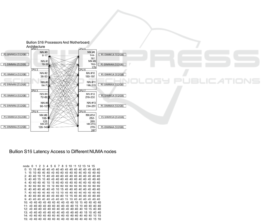
For instance, the Bullion S16 consists of 16 Intel
NUMA nodes each of them equipped with 18 cores.
Figure 1 shows how the CPUs are connected and
Figure 2 shows the memory distance between
different NUMA nodes.
The distance represents the relative latency for
accessing the memory from one CPU to another one.
For instance, a program in node 0 accessing data in
its own memory has a cost of 10, while accessing the
data in the memory attached to node 1 has a higher
cost, 15 (50% overhead). If data is the memory of any
of the 14 remaining nodes, the cost is 40. That is, it
costs 4 times more than accessing local memory of
node 0.
Figure 1: Bullion S16 Architecture.
Figure 2: NUMA distances in the Bullion S16.
Operating systems in general allocate threads on
the CPU with lowest usage. Therefore, the threads of
a process can be spread across several CPUs and
therefore the performance of the application can be
affected by remote access to the data. Linux systems
provide functions to bound threads to a CPU (e.g.,
libnuma) and even tools to bind a process to a CPU
(e.g., numactl). The numactl command also allows to
define where the memory is allocated for an
application, for instance, on a single CPU, on a set of
CPUs or interleaved among a set of CPUs.
3 DATA STREAMING ENGINES
Stream Processing (SP) is a novel paradigm for
analysing data in real-time captured from
heterogeneous data sources. Instead of storing the
data and then process it, the data is processed on the
fly, as soon as it is received, or at most a window of
data is stored in memory. SP queries are continuous
queries run on a (infinite) stream of events.
Continuous queries are modeled as graphs where
nodes are SP operators and arrows are streams of
events. SP operators are computational boxes that
process events received over the incoming stream and
produce output events on the outgoing streams. SP
operators can be either stateless (such as projection,
filter) or stateful, depending on whether they operate
on the current event (tuple) or on a set of events (time
window or number of events window). Several
implementations went out to the consumer market
from both academy and industry (such as Borealis
(Ahmad, 2005), Infosphere (Pu, 2001), Storm
(Foundation, 2015), Flink (Fundation, Apache
Flink® - Stateful Computations over Data Streams,
2014) and StreamCloud (Gulisano, StreamCloud: An
Elastic and Scalable Data Streaming System, 2012)).
Storm and Flink followed a similar approach to the
one of StreamCloud in which a continuous query runs
in a distributed and parallel way over several
machines, which in turn increases the system
throughput in terms of number of tuples processed per
second. UPM-CEP adds efficiency to this parallel-
distributed processing being able to reach higher
throughput using less resources. It reduces the
inefficiency of the garbage collection by
implementing techniques such as object reutilization
and takes advantage of the novel Non Uniform
Memory Access (NUMA) multicore architectures by
minimizing the time spent in context switching of SP
threads/processes.
Dynamic Data Streaming for an Appliance
471
4 UPM-CEP DATA STREAMING
ENGINE
UPM-CEP provides a client driver for streaming
applications, the JCEPC driver that hides from the
applications the complexity of the underlying system.
Applications can create and deploy continuous
queries using the JCEPC driver as well as register to
the source streams and subscribe to output streams of
these queries. During the deployment of a streaming
query the JCEPC driver takes care of splitting the
query into sub-queries and deploys them in the CEP.
Some of those sub-queries can be parallelized. For
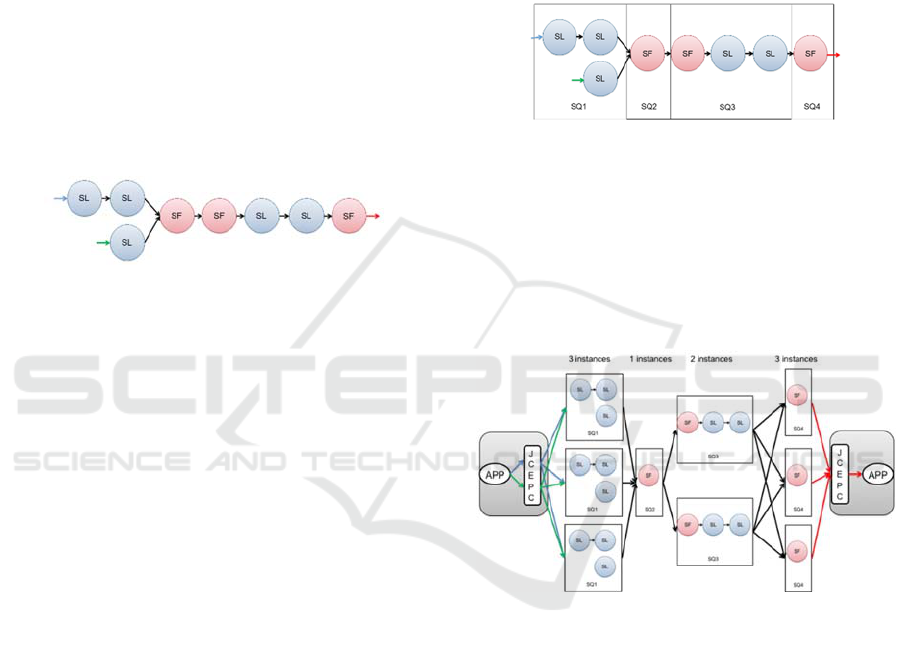
instance, the query in Figure 3 shows a data streaming
query made out 2 input streams and 8 operators. The
operators are either stateless (SL) or stateful (SF)
operators.
Figure 3: Data streaming query.
UPM-CEP has several stateless and stateful
operator implemented and users can create their own
customized operators. The stateless operators that can
be found are: 1) Map: that allows to select the desired
fields from the input tuple and create an output tuple
with those fields. 2) Filter: Only the tuples that satisfy
a defined condition are sent through the output
stream, the rest of tuples are discarded. 3) Demux:
sends the input tuples to all the output streams that
satisfies the defined conditions and 4) Union: Tuples
that arrives to the operator from different input
streams are sent to one output stream.
Regarding the stateful operators two window
oriented operators are available: 1) Aggregate: group
all tuples that are in the time or size window taking
into account defined functions executed over the
fields of all the tuples. Moreover, tuples can be
grouped into different windows if the group by
parameter is specified. 2) Join: Correlates tuples from
two different input stream. Two time windows are
created, one per input stream and when the windows
are slide tuples are joined creating one output tuple
taking into account a specified predicate.
UPM-CEP partitions queries into subqueries so
that, each subquery executes in a different node.
Figure 4 shows how the previous query is splitted into
four subqueries (SQ1, SQ2, SQ3 and SQ4). The
number of subqueries of a given query is defined by
the number of stateful operators. All consecutive
stateless operators are grouped together in a subquery
till a stateful operator is reached. That stateful
operator is the first operator of the next subquery.
This way of partitioning queries has proven to be
efficient in distributed scenarios (Gulisano,
StreamCloud: A Large Scale Data Streaming System,
2010). We have applied the same design principles to
UPM-CEP although it is not a distributed setup, the
same principles apply minimizing the communication
across NUMA nodes in this case and keeping the
same semantics a centralized system will provide.
Figure 4: Query partitioning.
Subqueries can be parallelized in order to increase
the throughput. Each instance of a subquery can run
in a different core in the same node. Figure 5 shows
how subqueries of the previous example could be
parallelized. There are 3 instances of SQ1, one
instance of SQ2, two instances of SQ3 and three
instances of SQ4.
Figure 5: Query parallelization.
The main challenge in query-parallelization is to
guarantee that the output of a parallel execution is the
same as a centralized one. If we consider a sub-query
made by only one operator, this challenge means that
the output of a parallel operator must be the same as
a centralized operator. On the other hand, window
oriented operators require that all tuples that have to
be aggregated/correlated together are processed by
the same CEP instance. For example, if an Aggregate
operator computing the total monthly operations of
the bank accounts for each client is parallelized over
three CEP Instances, it must be ensured that all tuples
belonging to the same user account must be processed
by the same CEP Instance in order to produce the
correct result.
ADITCA 2019 - Special Session on Appliances for Data-Intensive and Time Critical Applications
472
To guarantee the equivalence between centralized
and parallel queries, particular attention must be
given to the communications among sub-queries.
Consider the scenario depicted in
Figure 6
where there
are two sub-queries, Sub-query 1 and Sub-query 2,
with a parallelization degree of two and three,
respectively. If Sub-query 2 does not contain any
window oriented operator, CEP instances at Sub-
query 1 can arbitrary decide to which CEP instance of
Sub-query 2 send their output tuples. Output tuples of
Sub-query 1 are assigned to buckets. This assignment
is based on the fields of the tuple. Given B distinct
buckets, the bucket b corresponding to a tuple t is
computed by hashing one or more fields of the tuple
modulus B. All tuples belonging to a given bucket are
sent to the same CEP instance of the Sub-query 2.
Figure 6: Subquery Connections.
The fields to be used in the hash function depend
on the semantics of the window oriented operators
defined at Sub-query 2 and the mapping among
buckets and downstream CEP Instances depends on
the load balancing algorithm used in the CEP.
Join: if the join predicate has at least one equality
condition, it is an equi-join (EJ), otherwise it is a
cartesian product. For downstream operators of
type EJ, the hash function is computed over all the
fields used in the equalities plus the optional fields
which could appear in the group-by clause.
Aggregate: the fields used in the hash function are
all the fields used in the group-by parameter. In
this way, it is ensured that all tuples sharing the
same values of the attributes specified in the
group-by parameter are processed by the same
CEP instance.
UPM-CEP comes with this default partition strategy
used for splitting a query into sub-queries in the
absence of user defined split policies. According to
this strategy a new sub-query is created anytime one
of the following conditions is satisfied during the
query:
It is a stateful operator.
It is an operator with more than one input stream.
All the event oriented operators before the first
stateful operator are part of the same sub-query.
4.1 UPM-CEP Architecture
The UPM-CEP architecture consists of two main
components: the orchestrator and instance managers.
Other components are the reliable registry
(Zookeeper) and the metric server. Figure 7 depicts
how the CEP components can be deployed in a
scenario with several NUMA nodes or nodes.
Figure 7: CEP Components.
4.1.1 Orchestrator
The orchestrator is in charge of managing the rest of
the elements of the CEP. There is only one instance
of this component in a deployment. It deploys queries
and subqueries in the instance managers and balances
the load among different nodes running instance
managers.
The state of the orchestrator is kept in Zookeeper
(Fundation, Apache ZooKeeper, 2010) so that, if
there is a failure a new orchestrator can be run and
take its state from Zookeeper. Active replication
could be an alternative design however, although
fault-tolerance is easier to implement in this case, the
overhead of active replication of the orchestrator will
have an impact on regular processing (when there are
no failures).
4.1.2 Instance Managers
The instance manager is the component in charge of
running queries. Each instance manager runs on a
core of NUMA node and can run one or more
subqueries. Instance managers are single threaded.
Instance managers receive tuples either from
clients (through the JCEPC driver) or from other
instance managers. Instance managers must be aware
of the nature of the subquery it sends tuples. In a
scenario in which there is no parallelism, an instance
manger running a subquery will send all the data to
the next subquery. These means, tuples from the first
Dynamic Data Streaming for an Appliance
473
subquery are sent directly to the next one, this type of
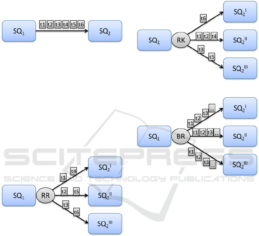
tuple sender process is called point to point balancer.
Figure 8 shows two subqueries SQ
1
and SQ
2
, both are
deployed using one instance manager. And tuples t1
to t6 are being sent from SQ
1
to SQ
2
by means of the
point to point balancer.
Figure 8: Point to Point Balancer.
However, if SQ
2
is deployed in several instances,
SQ
1
has to take into consideration the type of operator
is placed at the beginning of SQ
2
. If it is a stateless
operator, tuples from the previous instance manager
are sent in a round-robin fashion. For instance, Figure
9 represents the aforementioned scenario. SQ
2
has
been parallelized in three different instances and the
first operator is stateless, these means the tuples can
be handle by any of the SQ
2
instances. The round
robin balancer sends tuples t1 to t6 as presented, tuple
t1 is sent to the first instance, t2 is sent to the second
instance, t3 is sent to instance number 3 and the
process is repeated with tuples t4 to t6 beginning from
the first instance.
Figure 9: Round Robin Balancer.
Nevertheless, if the first operator is stateful these
means that tuples have to be handled by a specified
instance. For that cases a route key balancer is
required, taking into account the group by clause
specified in the operator configuration. Tuples
produced by SQ
1
are routed to the required SQ
2
instance, Figure 10 shows how the route key balancer
works sending tuples t1 to t6 to the different instances
of SQ
2
. Tuple t6 is sent to SQ
2
I
, tuples t1, t2 and t4
are sent to SQ
2
II
taking into account the route key and
finally tuples t3 and t5 are sent to SQ
2
III
.
To complete the types of balancer presented, the
UPM-CEP also defines a broadcast balancer of those
operators that requires to send the tuples to all the
instances. Figure 11 exposes an example of how
tuples are sent from SQ
1
to all SQ
2
instances.
Figure 10: Route key Balancer.
Figure 11: Broadcast Balancer.
5 DYNAMIC MIGRATION
The metric server component of the DSE stores all the
metrics related to the performance and resource usage
of the DSE. That is, input load, throughput and
latency of each operator, subquery and query running
in the system. Regarding the resource usage the DSE
monitors CPU, memory and bandwidth consumed by
each Instance Manager. If an Instance Manager is
saturated, dynamic migration will try to move one of
the subqueries running on that IM to another less
loaded IM.
Dynamic migration also happens when a new
Instance Managers are provisioned to the DSE, or
when moving sub-queries from an Instance Manager
running on one NUMA node to another one. In the
first case, the goal of moving a sub-query is to
distribute the load between an overloaded Instance
Manager and a new one. In the second case, the
reconfiguration can move two sub-queries that are
ADITCA 2019 - Special Session on Appliances for Data-Intensive and Time Critical Applications
474
exchanging data with high frequency on the same
NUMA node in order to take advantage of the local
memory.
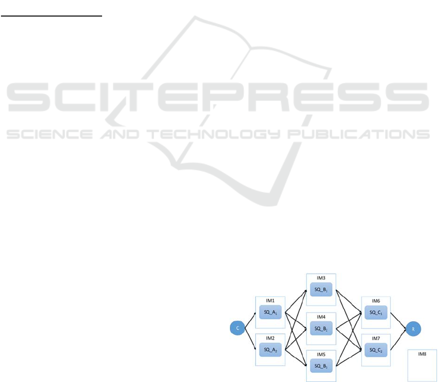
We defined a migration protocol for the DSE:
State Transfer. To explain the migration protocol, we
will use the query depicted in Figure 12. In the figure
there is a query Q with three sub-queries named
SQ_A, SQ_B and SQ_C. SQ_A and SQ_C are
deployed with 2 instances each and SQ_B is deployed
using 3 instances. Each sub-query is deployed in its
own Instance Manager. C and R represent
respectively the client application sending tuples and
the receiver application waiting for the query results.
Moreover let us assume that we want migrate SQ_B
2
from IM4 to IM8.
The completion time for the State Transfer
protocol depends on the state size, that is, the number
of tuples kept in the window structures at the time the
reconfiguration is issued.
State Transfer Protocol:
1. The protocol starts deploying a new Instance of
SQ_B (SQ_B
2NEW
) in the Instance Manager IM8.
2. Then, the upstreaming sub-queries,SQ_A
1
and
SQ_A
2
are informed that the sub-query SQ_B
2
will
be moved from IM4 to IM8. As a result of this
action, the IMs running SQ_A
1
and SQ_A
2
flush
their output streamss, and turn in a reconfiguration
mode where they start buffering all new output
tuples with destination SQ_B
2
.
3. IM4 takes a snapshot of the state (if any) of SQ_B
2
and
transfers it to the new instance SQ_B
2NEW
running in IM8.
4. Once the state is transferred, SQ_A
1
and SQ_A
2
first send to SQ_B
2NEW
all the tuples stored in the
meanwhile in the buffers and then turn themselves
back in the normal operation mode.
6 FAULT-TOLERANCE
The simplest solution to provide high availability in a
datacentre is simply to deploy the DSE in another
appliance (backup) and resume the processing of
tuples in that appliance if the active one fails
(primary). A replication manager is needed for
detecting the failure of the primary appliance. The
replication manager also sends the queries to be
deployed to the backup. These queries are registered
in the backup during regular processing. When the
primary fails in a primary-backup scenario in a data
centre, the backup will redeploy all the queries and
resume the processing.
This solution is valid if some tuples can be lost
and this does not affect the application. However, if
no tuple should be missed then, either an active
replication approach is followed or some check
pointing mechanisms must be in place. In that case
some mechanisms are needed to store the tuples so
that they can be replayed in case of a failure. If tuples
are replayed, two semantics are possible: at least once
or exactly once. That is, tuples are processed exactly
once (there are no duplicates in case of failures) or
there can be duplicates (at least once). The exactly
once policy is more expensive as it needs to register
every outcome. The DSE currently implements at
least once semantics by implementing active
replication. That is, all events are sent to the two
appliances, and both of them process all events. The
sinks that receive the outcome of the data streaming
engine will receive output events from the two
appliances and filters them in order to avoid sending
duplicates to the client during regular processing.
When a failure happens, one of the appliances will
stop sending output events. At that point the sink will
receive events from one appliance and send these
results to the client. In this scenario there will be no
duplicate outcomes (exactly once guarantee).
7 PERFORMANCE EVALUATION
UPM-CEP performance has been measured using the
Intel HiBench benchmark (Intel, 2017). This
benchmark allows to evaluate different big data
frameworks and contains 19 different workloads that
are distributed in: micro, machine learning, sql,
graph, websearch and streaming. Specifically, we
focus on the streaming workloads: 1) Identity: This
workload reads input tuples and produces the same
tuples without any modification. A map operator is
defined with the same input and output fields. 2)
Repartition: Modifies the parallelism level and
distributes the load in a round robin fashion. It defines
a map operation that copies the input to the output.
Figure 12: Example query for the migration protocol.
Dynamic Data Streaming for an Appliance
475
The query is deployed several times. Tuples are sent
to the different instances of the query in a round robin
fashion. 3) Stateful wordcount: counts the number
word. This workload requires several operators, first
of all a map operator picks only the word from the
input tuple; an aggregate operator with a number of
tuples window and a group by condition based on the
word is added. This query tests the route key balancer.
4) Fixed Window: This workload tests the
performance of the time window operator group by a
field.
This streaming workload has been implemented
to be executed in four different streaming frameworks
such as Flink, Storm, Spark and Gearpump. We have
implemented same workloads for the UPM-CEP. In
this evaluation we use the Fixed Window query,
which aggregates the connections to a server from
each IP address during a period of time. After this
time expires, a tuple with the timestamp of the first
and last connection from that IP address and the
number of connections during that period is
produced.
Figure 13: HiBench Fixed Window Topology.
This query, represented in Figure 13, is
implemented as a map operator that selects the IP
address and the connection time (timestamp) from
incoming tuples. Then, an aggregate operator with a
time window of 30 seconds per IP is defined. When
the window is triggered a tuple is emitted with the
timestamp of the first tuple in the window and the
number of tuples. To finalize a map operator, add an
extra field to the tuple with the timestamp at this
moment. The code below corresponds to the
aggregate function.
AggregateOperatorConfig aggregator = new
AggregateOperatorConfig("aggregator",
PROJECTOR_STREAM, AGGR_STREAM);
aggregator.setWindow(OperatorEnums.WindowTyp
e.TIME, wsize, wadv);
aggregator.addGroupByField("ip");
aggregator.addIntegerFunctionMapping("counter",
OperatorEnums.Function.COUNT, "ip");
aggregator.addLongFunctionMapping("startts",
OperatorEnums.Function.LAST_VAL,
ParameterStore.TIMESTAMP_USER_FIELDNAM
E);
aggregator.addStringFunctionMapping("ip",
OperatorEnums.Function.LAST_VAL, "ip");
query.addOperator(aggregator );
The goal of the evaluation is to show the performance
during load balancing and when failures occur.
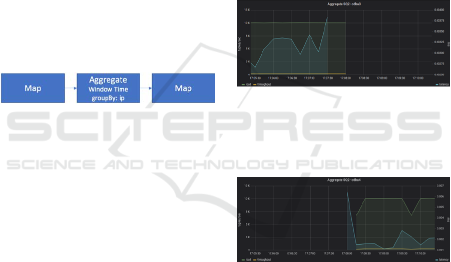
For the replication protocol we show the
throughput and latency of subquery 2, the one starting
with the aggregate operator before the failure, while
the migration happens and after the system is
reconfigured. Figure 14 shows those values before the
migration happens. At that point 10,000 tuples are
received by this subquery. The response time is 0.04
ms.
Figure 14: Subquery migration, Load and response time
before the migration.
Then, the query is migrated to another node.
Figure 15 shows the load and response time after the
query is migrated. It takes around 20 seconds to
transfer the state and start processing tuples again.
Figure 15: Query migration.
For the evaluation of the fault-tolerance protocol we
present the behaviour of the data source and the data
sink. The data source is in charge of duplicating the
tuples and sending them to both nodes. The data sink
receives the output tuples from the two nodes and
outputs a single one. The first time a tuple arrives
from one of the nodes, it outputs that tuple and keeps
it in memory till the duplicate arrives or a failure
happens. In the former case the tuple is eliminated,
while in the latter case, the tuples are directly send to
the client.
ADITCA 2019 - Special Session on Appliances for Data-Intensive and Time Critical Applications
476
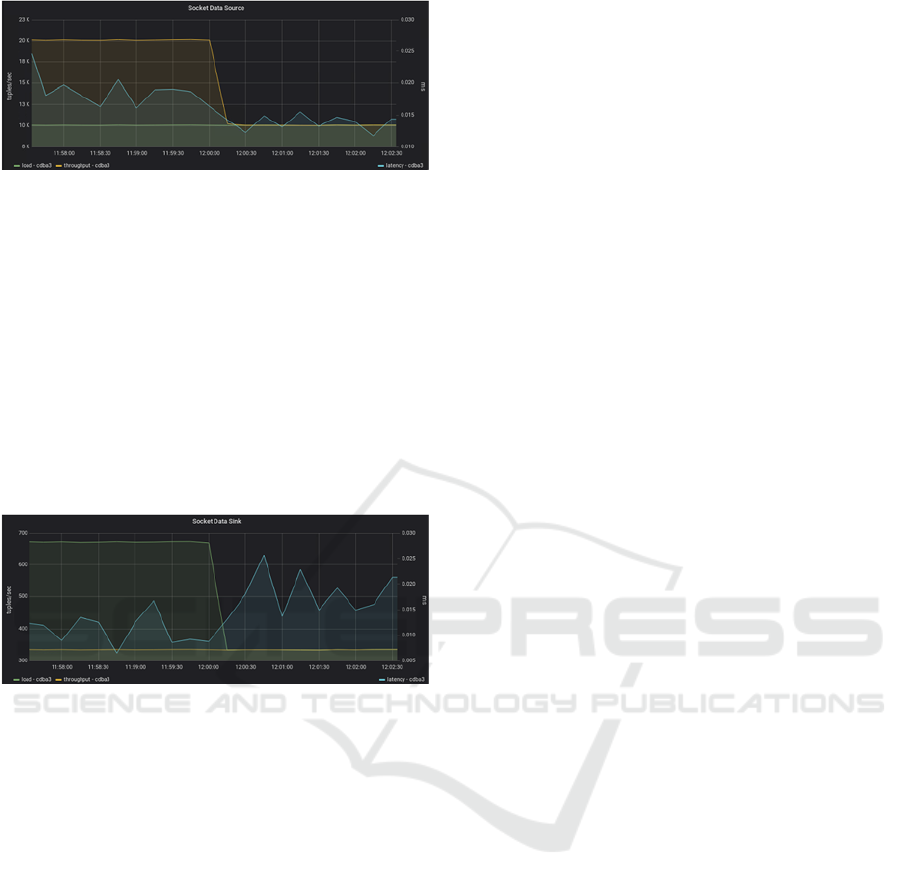
Figure 16: Data Source.
Figure 16 shows that the data source receives 10
000 tuples and sends 20 000 tuples while there are two
replicas, then a failure happens and it only sends the
tuples to the available replica.
Figure 17 shows the number of tuples the data
sink receives while the two replicas are running (680
tuples), when the failure happens one of the replicas
stops sending tuples and therefore, the data sink
receives 340 tuples per second. In both the former
case it filters duplicates and sends half of the tuples.
While in the latter case it sends the same amount of
tuples but, there is no filtering.
Figure 17: Data sink.
8 CONCLUSIONS
In this paper we have presented the migration and
fault-tolerance protocols of UPM-CEP and their
performance running the HiBench benchmark.
As future work we plan to implement other fault-
tolerance protocols providing more relaxed
semantics.
ACKNOWLEDGEMENTS
This work has received funding from the European
Union’s Horizon 2020 research and innovation
programme under grant agreements No 732051,
779747, the Madrid Regional Council, FSE and
FEDER, projects Cloud4BigData and EDGEDATA
(grants S2013TIC2894, S2018/TCS-4499), the
∫œMinistry of Economy and Competitiveness
(MINECO) under project CloudDB (grant TIN2016-
80350).
REFERENCES
Ahmad, Y. e. (2005). Distributed Operation in the Borealis
Stream Processing Engine. ACM SIGMOD
International Conference on Management of Data,
882-884.
Foundation, A. S. (2015). Apache Storm. Obtenido de
http://storm.apache.org/
Fundation, T. A. (2010). Apache ZooKeeper. Obtenido de
https://zookeeper.apache.org/
Fundation, T. A. (2014). Apache Flink® - Stateful
Computations over Data Streams. Obtenido de
https://flink.apache.org/
Gulisano, V. e. (2010). StreamCloud: A Large Scale Data
Streaming System. 126-137.
Gulisano, V. e. (2012, 12 23). StreamCloud: An Elastic and
Scalable Data Streaming System. IEEE Transactions
on Parallel Distributed Systems, 2351-2365.
Intel. (2017). HiBench. Obtenido de https://github.
com/Intel-bigdata/HiBench
Pu, C. e. (2001). Infosphere Project: System Support for
Information Flow Applications. (25-34, Ed.)
SIGMOD(30), 25-34.
Dynamic Data Streaming for an Appliance
477
