
Material Recognition for Mixed Reality Scene including Objects’
Physical Characteristics
Kenzaburo Miyawaki and Soichi Okabe
Faculty of Information Science and Technology, Osaka Institute of Technology, Hirakata-city, Osaka-fu, Japan
Keywords:
Mixed Reality, Deep Learning, Material Recognition.
Abstract:
Mixed Reality (MR) is a technique to represent scenes which make virtual objects exist in the real world.
MR is different from Augmented Reality (AR) and Virtual Reality (VR). For example, in MR scenes, a user
can put a virtual Computer Graphics (CG) object on a desk of the real world. The virtual object can interact
with the real desk physically, and the user can see the virtual object from every direction. However, MR only
uses position and shape information of real world objects. Therefore, we present a new MR scene generator
considering real world objects’ physical characteristics such as friction, repulsion and so on, by using material
recognition based on a deep neural network.
1 INTRODUCTION
Mixed Reality (MR) has attracted more and more at-
tention. That is a new technique which extends Aug-
mented Reality (AR) and Virtual Reality (VR), but
different from them. MR can show very interest-
ing representation which mixes virtual objects and
real space. For example, if you put a virtual apple
Computer Graphics (CG) model on a desk of the real
space, the virtual apple has physical interaction with
the desk of the reality and then has been set on the
top of the desk. Additionally, you can see the virtual
apple from all directions. When there is another real
object on the desk of the real space and the virtual ap-
ple is moved to behind the real object, the part of the
apple will be hidden by the real another object. Thus
MR constructs the world that makes virtual objects
can interact with real objects.
However, the current MR only uses the position
and shape information of the virtual and real objects.
Therefore the interaction between virtual objects and
real objects is only collision of a constant pattern.
From this consideration, we propose a new method
for MR which can represent more realistic interaction
between virtual objects and real objects. Specifically,
our method recognizes materials of the real world ob-
jects, estimates their physical characteristics, such as
friction and repulsion, and builds MR scene which the
characteristics are reflected on. For example, imagine
a situation where a bouncy ball is dropped on a sofa.
It is thought that the ball dropped on the sofa does not
bounce much due to the influence of the cushion, and
it can not roll so long time, because it will stop imme-
diately by friction with the fabric. If this is done with
existing MR using a virtual bouncy ball, it will show
the same movement of jumping and rolling regardless
of falling on a sofa or on a floor. A sofa is soft and
easy to absorb shocks and a floor is hard, however
generic MR does not consider such physical charac-
teristics of the real objects. Contrary to this, our new
MR scene generator considers friction, repulsion and
contact sound of the real world objects. This method
recognizes the real world objects’ materials, estimates
thier physical characteristics and reflects the informa-
tion into the MR scene, so that realize more realistic
interaction between virtual and real objects.
The rest of this paper is organized as follows. In
the chapter 2, we describe related works. Chapter 3
shows our method overview. After that, we explain
the detailed algorithms in chapter 4. Chapter 5 shows
a brief demonstration of our MR scene generator, and
chapter 6 shows experiments of the material recogni-
tion that is an important function of our method. Fi-
nally, we conclude this paper in chapter 8.
2 RELATED WORKS
There are several studies that make virtual objects ap-
pear more realistically in MR scenes.
For example, Kakuda (Kakuta et al., 2008) uses
the MR technology to restore cultural properties.
Miyawaki, K. and Okabe, S.
Material Recognition for Mixed Reality Scene including Objects’ Physical Characteristics.
DOI: 10.5220/0008332502190224
In Proceedings of the 11th International Joint Conference on Knowledge Discovery, Knowledge Engineering and Knowledge Management (IC3K 2019), pages 219-224
ISBN: 978-989-758-382-7
Copyright
c
2019 by SCITEPRESS – Science and Technology Publications, Lda. All rights reserved
219
Their method generates shadow images of virtual ob-
jects in real time based on the light source distribution
in the sky. That can make appropriate shadowing and
improve the reality of virtual objects. Inaba (Inaba
et al., 2012) realized robust feature point matching
against luminance changes for natural position align-
ment of virtual objects overlaying on the real world.
As described above, although there are many stud-
ies to make natural looks of virtual objects for MR, we
can not see so many researches for natural interaction
between virtual objects and real objects, that consid-
ers the physical characteristics of the material of real
objects.
3 METHOD
In this research, material recognition is a key func-
tion. That is based on the image recognition us-
ing deep learning, and repulsion and friction are es-
timated. At first, color image is acquired by a de-
vice having a built-in depth sensor. We used Kinect
v2
1
as the sensor. Object detection and recognition
are executed against the image by deep neural net-
work. Additional to this, transparent 3D meshes of
the detected objects are built from their point clouds
simultaneously. Next, each detected object’s material,
such as metal, wood, fabric and so on, are classified
by deep learning, and physical characteristics corre-
sponding to the material will be added into their 3D
meshes. After that, all of the 3D meshes which in-
clude physical characteristics are merged and overlay
on the real world image. Inside of this scene, virtual
objects will be affected by the physical characteristics
of the 3D meshes, and more realistic representation is
possible. We can make a virtual ball’s bound motion
and contact sound change by the recognized material
of a floor where the ball dropped on.
Note that, the physical characteristics are not
strictly calculated in this research. They are led from
common sense. For example, in the case of fabric, it
is “soft” and “rough”, and in the case of metal, it is
“hard” and “slippery” in general. The definitions are
made in advance and added into the 3D meshes.
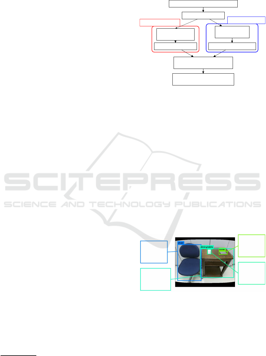
4 SYSTEM FLOW
Figure 1 shows the flow of our system.
The system roughly consists of four processes:
object detection, material recognition, generation of
1
Kinect v2 https://developer.microsoft.com/ja-jp/
windows/kinect/
Color & depth image acquisition
Object detection
Clipping of
object image
Material recognition
Point cloud
modification
3D mesh construction
Adding material information
into the 3D meshes
Combinning all meshes
to build a Mixed Reality scene
Image Processing
Mesh generating
Figure 1: System flow.
3D meshes corresponding to the objects, and adding
material information to the 3D meshes.
This section gives a detailed explanation of these
processes.
4.1 Object Detection
First, our system acquires a color image and a depth
image from the Kinect sensor. The color image is
aligned to the depth image. From the color image, real
world objects are detected by a deep neural network.
We used YOLO (Redmon et al., 2015), which is an
object detection and recognition framework based on
deep neural network algorithms.
Figure 2 shows a sample result of the object de-
tection and recognition that shows names and areas of
the objects. This result is used for the material recog-
nition and the 3D mesh generation thereafter.
Name:chair
left-top
(28, 80)
right-bottom
(284, 472)
Name:dining table
left-top
(278, 122)
right-bottom
(641, 437)
Name:book
left-top
(482, 152)
right-bottom
(572, 186)
Name:book
left-top
(355, 129)
right-bottom
(397, 186)
Figure 2: Example of object detection.
Since this research places importance on what
kind of material the detected objects are made up, it
does not need perfect accuracy of the object recog-
nition. Only objects’ areas are critical information,
and mis-recognition is no problem. Figure 2 shows
an example of mis-recognition. The “pencase” is rec-
ognized as a “book”, but their areas are correctly de-
tected so that the image clips of the objects can be
extracted for the material recognition.
KMIS 2019 - 11th International Conference on Knowledge Management and Information Systems
220
4.2 Material Recognition
After the object detection, material recognition fol-
lows. For the recognition, material image clips are
extracted as separate images from the color image,
based on the areas of the objects acquired in the
section 4.1 During this image extraction, the system
crops 10% of the top, bottom, left, and right pixels of
the object area so that only its main material image
remains.
Next, material recognition is performed on each
trimmed image by deep learning. We used Caffe (Jia
et al., 2014) as a framework of deep learning and used
GoogLeNet(Szegedy et al., 2014) as a model of deep
neural network. Learning data is image collection that
shows typical features of the materials. We collected
the images from Web. Figure 3 shows example im-
ages of the learning data.
Metal
Cloth
Wood
Plastic
Figure 3: Material image samples.
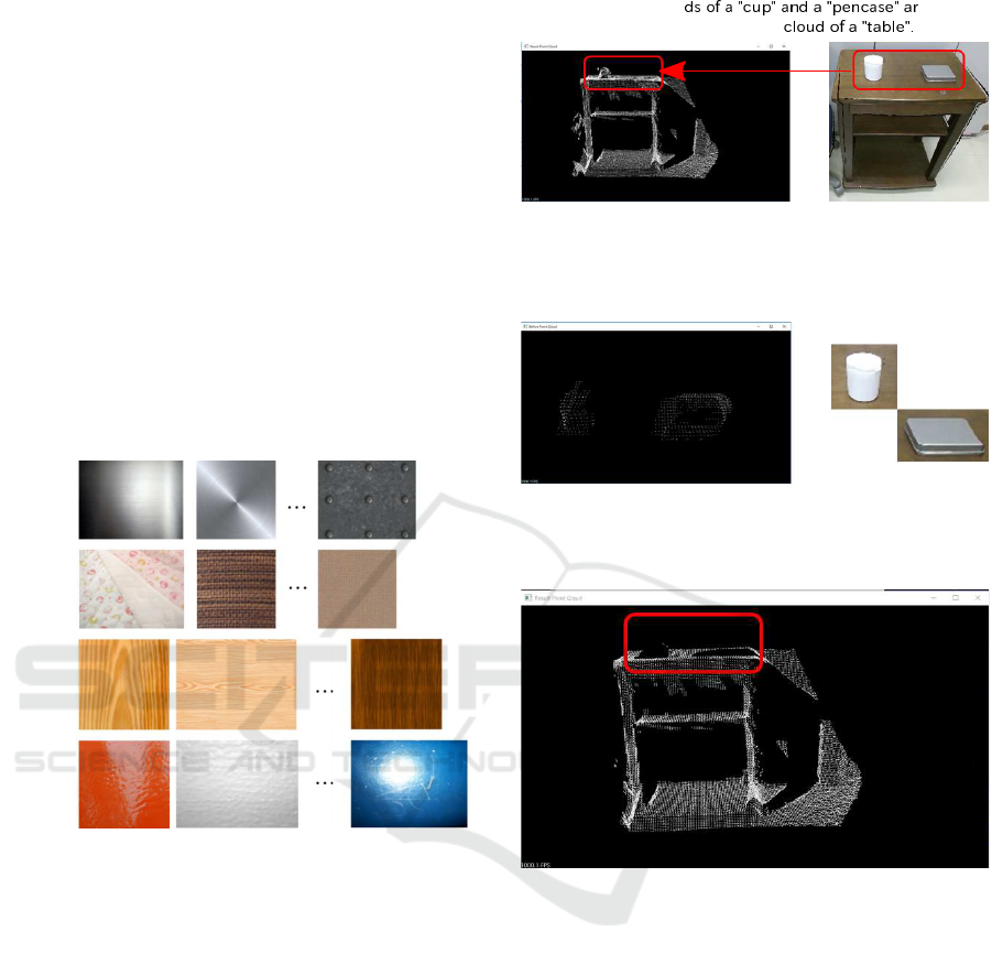
4.3 Point Cloud Modification and 3D
Mesh Construction
3D mesh Construction is performed concurrently with
the process of the section 4.2. As preparation for the
3D mesh construction, point clouds are built from the
depth image based on the areas of the detected ob-
jects. However, there may be a case where the point
clouds of different objects partially overlap as shown
in Figure 4
Figure 4 is a overlappingexample. When the point
cloud of the “table” is built, the cloud includes point
clouds of the “pen” and the “cup”, they are noise
for the “table” and should be scraped off. We used
kdtree(Indyk et al., 1997) to remove them.
Figure 5 shows the overlapping objects whose
point clouds are included into the point cloud of the
“table”. We extract their overlapping points from the
point cloud of the “table” by the kdtree search and
Point clou e
included into the point
Figure 4: Overlapping of the point clouds.
Point clouds of the "cup" and the "pencase".
They should be removed from the point cloud of
the "table".
Figure 5: Overlapping objects.
The point cloud of the "table".
Other objects' point clouds were removed.
Figure 6: Removal of other objects’ point clouds.
remove the points. The remaining points are correct
points of the “table”. Figure 6 shows the result, which
is clearly removed the overlapping objects’ points.
3D meshes are constructed from such clean point
clouds.
4.4 Adding Material Information into
the 3D Meshes
The information of the materials obtained in the sec-
tion 4.2 is associated with individual meshes to create
a MR scene which makes virtual objects physically
interact with real objects. The scene generated here
is not a mere collision detection, but is a scene added
with physical characteristics such as a friction coef-
ficient according to the real world. In this research,
friction and repulsion coefficient and contact sound
Material Recognition for Mixed Reality Scene including Objects’ Physical Characteristics
221
are selected as additional attributes to give to the 3D
meshes. These attributes were registered in advance
and stored in a database for typical materials such as
wood, metal, fabric and plastic.
By the process of the section 4.2 and 4.3, the 3D
meshes already have been added with the names of
what materials they consist of. The coefficients of
the correspondingobject are retrievedfrom the above-
mentioned database and given to its mesh to generate
a MR scene.
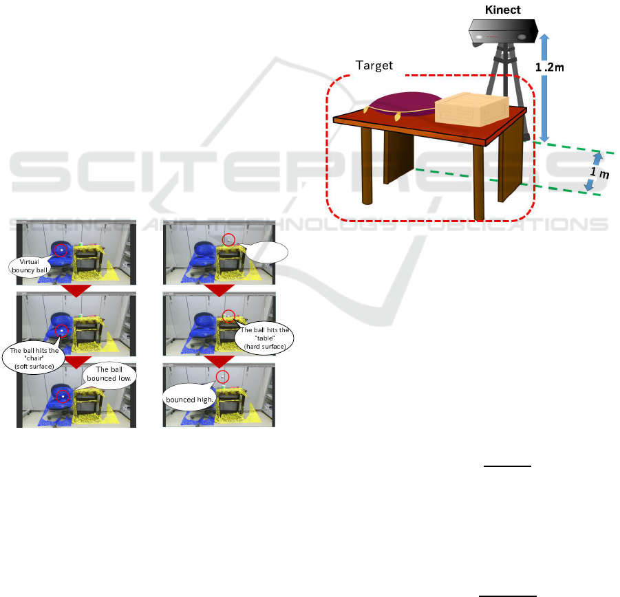
5 DEMONSTRATION
Figure 7 shows a state of bouncingwhen a virtual rub-
ber ball is droppedon a generated 3D mesh with phys-
ical characteristics. The red, green, blue and yellow
points have physical characteristics of “metal”, “plas-
tic”, “fabric” and “wood” respectively.
It can be seen that the “table” made of wood prop-
erly rebounds the ball upward highly. On the other
hand, in the case of “chair” whose surface is fabric,
the ball can not rebounce highly. Although we cannot
represent in this paper, the contact sound is changed
according to the materials appropriately. This is suc-
cess case of constructing more realistic MR scene
than the existing MR. The success ratio depends on
the material recognition and it was preferable result.
We show that in the next chapter.
Virtual
bouncy ball
The ball
Figure 7: Demonstration. (Yellow points and blue points
are recognized as “wood” and “fabric” respectively).
6 EXPERIMENTS
6.1 Method and Environment
The purpose of the experiment is to confirm whether
the object detection and the material recognition are
properly performed. For this, we prepared some ob-
jects whose main materials can be classified into 4
kinds and arranged the objects randomly, and process-
ing is performed in the order of object detection and
material recognition to confirm their accuracy. We se-
lected “fabric”, “metal”, “plastic” and “wood” as the
target materials.
This series of the object detection and material
recognition is regarded as one set, and 30 trials were
conducted. We changed the kind and number of the
objects, and rearrange the objects’ positions, to make
all situations of the trials become different.
Note that, since the system is supposed to be used
indoors, all experiments were conducted indoors, and
Kinect sensor looks at the target object from a certain
distance as shown in Figure 8.
objects
Figure 8: Experimental environment.
The configuration of Figure 8 is based on the as-
sumption of a situation where a MR user who wears a
head mounted display and sits on a chair looks at the
objects on the table.
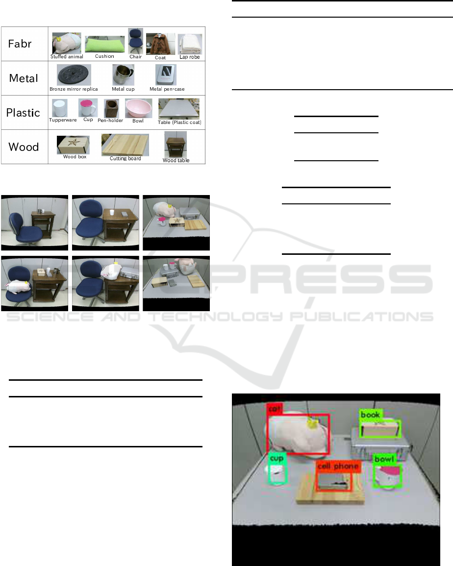
The objects prepared for the experiment are 15
categories that are shown in Figure 9, and sample sit-
uations of the experiment are shown in Figure 10. We
checked a success count of the object detection and
the material recognition for each object on the all tri-
als, and calculated their success ratio. The success
ratio of the object detection is calculated by the fol-
lowing equation.
Success
od
=
O
detected
O
total
(1)
Where Success
od
is the succes ratio of the object de-
tection, O
detected
is the count of detected objects and
O
total
is the count of objects located on the situations.
O
detected
and O
total
are summation over the 30 trials.
The success ratio of the material recognition is
calculated by the following equation.
Success
mr
=
M
recognized
O
detected
(2)
KMIS 2019 - 11th International Conference on Knowledge Management and Information Systems
222
Where Success
mr
is the succes ratio of the material
recognition and M
recognized
is the success count of the
material recognition. M
recognized
is summation as well
as O
detected
.
ic
Figure 9: Target objects.
Figure 10: Target situations.
Specifications of a computer used for this experi-
ment are shown in the Table 1.
Table 1: Specifications of a computer for the experiment.
Item Specification
CPU Intel Core i7-6700K
Main Memory 16GB
GPU NVIDIA GeForce GTX 980i
GPU Memory 6GB
6.2 Results
According to the Table 2, 3 and 4, the overall succes
ratio of the object detection and the material recogni-
tion was 81% and 89% respectively.
Table 2: Counts of the object detection and material recog-
nition.
Item Count
O
total
Total objects over the 30 trials
123
O
detected
Success count of the detection
100
M
recognized
Success count of the material recognition
89
Table 3: Success ratio of the detection and the recognition.
Item Ratio
Success
od
81%
Success
mr
89%
Table 4: Success ratio of the recognition for each material.
Material Success ratio
Fabric 80.5%
Metal 85.1%
Plastic 57.9%
Wood 87.2%
7 DISCUSSION
7.1 Object Detection
The succes ratio of the object detection was 81%. Fig-
ure 11 shows an example shot of a object detection
failure. The “cutting board” can not be detected, be-
cause of occlusion. We have to consider more robust
algorithms against the occlusion.
Figure 11: Object detection failure.
Material Recognition for Mixed Reality Scene including Objects’ Physical Characteristics
223

7.2 Material Recognition
The succes ratio of the material recognition was 89%
and was preferable result. As shown in the Table 4,
“wood” and “metal” was good result. “Wood” materi-
als has grain and “metal” materials has specular high-
light. It is supposed that such appearances became
strong features which can distinguish them from other
materials. “Fabric” was moderate result also. We es-
timate that its rough surface became a good feature of
the “fabric” materials.
On the other hand, “plastic” was very hard to rec-
ognize. “Plastic” materials have specular highlight
like as the “metal”. We corrected learning samples
of the “plastic” while focuesd on such specular high-
light. However, object image clips extracted by the
object detection, did not have enough specular high-
light. This may be improved by more appropriate se-
lection of learning samples.
From the aspect of object location, overlapping of
objects dropped the success ratio. For example, when
some objects, which are composed of the “metal”,
“fabric” and so on, were put on a “table” whose sur-
face is “plastic”, the material of the “table” was not
classified successfully. This is a natural result, and we
have to use pixel level image segmentation to solve
this problem.
8 CONCLUSIONS
In this paper,we proposeda method to represent inter-
actions between virtual objects and real objects in MR
scene more realistically than conventional MR tech-
nologies by the material recognition of objects in the
real space. At first, RGB-D camera grabs a color im-
age and a depth image. From the color image, our
system detects objects to get the positions of objects
in the real space. Then, material recognition using
deep learning is performed over the objects’ image
clips, and 3D meshes of the detected objects are con-
structed. After that, the results of the material recog-
nition is reflected to each corresponding object’s 3D
mesh. Physical characteristics, such as friction and re-
pulsion coefficient and contact sound, are added into
the 3D meshes during the process. By overlaying the
3D meshes on the real world image, we can get more
realistic MR scene where not only the virtual objects
can interact with real objects, but also the motion of
the virtual objects changes by difference of materials
of the real objects. Our method will be applicable to
realize more realistic MR world which can be used to
many fields, such as sports with virtual balls, simula-
tion with virtual objects, and so on.
Currently, our method only recognizes the kind of
materials, and it does not consider how the material is
processed. For example, metal has been assumed to
be smooth on the surface, but some of them have been
rough machined. Similarly, varnished wood products
may have a smooth surface, but rough wooden objects
also exist. It is thought that more natural expression
becomes possible by considering not only the mate-
rial but also how its surface is processed. Addition-
ally, we have to consider pixel level object recogni-
tion. We used YOLO for ojbect recognition, and it
caluculates object’s bounding box. The bounding box
always includes other objects and it will affect mate-
rial recognition. We focuse on such points and con-
tinue to improve our method.
ACKNOWLEDGEMENTS
This work was supported by JSPS KAKENHI Grant
Number 17K01160.
REFERENCES
Inaba, M., Banno, A., Oishi, T., and Ikeuchi, K. (2012).
Achieving robust alignment for outdoor mixed reality
using 3d range data. In Proceedings of the 18th ACM
Symposium on Virtual Reality Software and Technol-
ogy, VRST ’12, pages 61–68, New York, NY, USA.
ACM.
Indyk, P., Motwani, R., Raghavan, P., and Vempala, S.
(1997). Locality-preserving hashing in multidimen-
sional spaces. In Proceedings of the Twenty-ninth
Annual ACM Symposium on Theory of Computing,
STOC ’97, pages 618–625, New York, NY, USA.
ACM.
Jia, Y., Shelhamer, E., Donahue, J., Karayev, S., Long, J.,
Girshick, R., Guadarrama, S., and Darrell, T. (2014).
Caffe: Convolutional architecture for fast feature em-
bedding. arXiv preprint arXiv:1408.5093.
Kakuta, T., Oishi, T., and Ikeuchi, K. (2008). Fast shad-
ing and shadowing of virtual objects using shadow-
ing planes in mixed reality. The journal of the Insti-
tute of Image Information and Television Engineers,
62(5):788–795.
Redmon, J., Divvala, S. K., Girshick, R. B., and Farhadi, A.
(2015). You only look once: Unified, real-time object
detection. CoRR, abs/1506.02640.
Szegedy, C., Liu, W., Jia, Y., Sermanet, P., Reed, S.,
Anguelov, D., Erhan, D., Vanhoucke, V., and Rabi-
novich, A. (2014). Going deeper with convolutions.
In Large Scale Visual Recognition Challenge 2014,
ILSVRC ’14.
KMIS 2019 - 11th International Conference on Knowledge Management and Information Systems
224
