
ANALYSIS OF THE ARCHITECTURE AND RELIABILITY
OF DATA TRANSMISSION NETWORK USED FOR
RADIO BASED CAB SIGNALING SYSTEM
Wang Junfeng, Zhang Yong, Wang Huashen and Wang Xishi
School of Electronics and Information Engineering, Beijing Jiaotong University, Beijing, 100044, P. R. China
Keywords: Radio based cab signaling, Communication based train control, Radio transmission, Network
Abstract: The application background and basic structure of train control system based on the combination of Radio
Based Cab Signaling (RBCS) and Automatic Train Protection (ATP) is introduced. The architecture of the
data transmission network used for RBCS is analyzed in detail, together with the reliability of radio data
transmission.
1 INTRODUCTION
Communication Based Train Control (CBTC)
system is the development trend of train control
techniques, which has many advantages compared
with Track circuit Based Train Control (TBTC)
system. For example, bi-directional train-track
communication with large information volume can
be realized; close-looped train control can be formed
to improve train operation safety; moving block or
virtual block can be implemented to enhance traffic
efficiency.
Chinese Ministry of Railways (MOR) is now
advocating CBTC techniques, and has made a
strategy to develop Chinese Train Control System
(CTCS) which is now under stepwise
implementation. CTCS consists of five application
levels, from level 0 to level 4, in which level 3 and
level 4 will be based on CBTC techniques. In the
near future, part of the technique will be applied on
Qinghai-Tibet Railway and Datong-Qinghuangdao
Railway.
The Qinghai-Tibet Railway is built on a plateau
with perennial frozen soil and very harsh climate.
The lowest temperature is –45.2°C and the
maximum temperature difference is 35°C. Under
these conditions, the parameter of track circuit will
change considerably, resulting in the unstable
operation of track circuit. Especially, the insulation
joint of track circuit will be easily damaged. To the
Datong-Qinghuangdao Railway which is a dedicated
coal line, a transport capacity expansion plan will
soon be carried out, with the goal to increase train
weight from 10,000 tons to 20,000 tons. As a result,
the traction current will reach as high as
1000~1500A, causing the unbalanced current to
exceed the standard by a great margin, which will
directly affect the normal operation of track circuit.
In view of above situations, the MOR has
decided to use radio to transmit train control
information, and has started the research on Radio
Based Cab Signaling (RBCS) system, which is now
under experiment.
After giving a brief introduction to the train
control system based on the combination of RBCS
and ATP system, this paper will focus on analyzing
the architecture of the radio transmission network
used for RBCS, together with the reliability of radio
data transmission.
2 RBCS SYSTEM
RBCS is a kind of device that transmits cab signal
and train control information by means of radio. It
consists of two parts: the station control equipment
and the onboard equipment. The transmission
network can use either radio data transceiver,
GSM-R or TETRA as the transmission media.
There are two types of RBCS. One type is called
continuous RBCS because it can provide cab signal
both at stations and in sections; another type is
called approaching continuous RBCS because it can
only provide cab signal when a train is running
within station area.
RBCS can work with onboard ATP equipment,
394
Junfeng W., Yong Z., Huashen W. and Xishi W. (2004).
ANALYSIS OF THE ARCHITECTURE AND RELIABILITY OF DATA TRANSMISSION NETWORK USED FOR RADIO BASED CAB SIGNALING
SYSTEM.
In Proceedings of the First International Conference on Informatics in Control, Automation and Robotics, pages 394-397
DOI: 10.5220/0001126303940397
Copyright
c
SciTePress

interrogator/balise, station interlocking, axle
counters and so on to realize close-looped train
control. As a result, train operation can be
continuously tracked and monitored, thus enhancing
train operation safety, reducing trackside equipment
and lowering maintenance cost.
The working principle of the approaching
continuous RBCS can be briefly described as
following. When a train enters the effective working
area of RBCS, its onboard equipment will apply for
registration to the SCC. Upon receiving the
registration information, the SCC will pick up the
cab signal information related to the train from the
station interlocking and send it to the train. After
receiving the cab signal information, the onboard
equipment will indicate the cab signal to the driver
and relay it to the ATP onboard equipment. At the
same time, train position and speed, the return
receipt of cab signal and so on are sent back to the
SCC in order to verify the correctness of the
transmitted information. When the train exits the
RBCS effective working area, it will be deregistered
by the SCC.
3 THE ARCHITECTURE OF DATA
TRANSMISSION NETWORK
The radio data transmission network is the
foundation of RBCS, and is one of the key technical
issues. Many issues concerning the transmission
network should be properly addressed, such as
network architecture, transmission method,
addressing mode, common frequency interference,
frame collision, data transceiver deadlock, radio
coverage, handover, communication protocol and so
on.
The approaching continuous RBCS uses the
commercial radio data transceiver to form a data
transmission network. There is a onboard radio on
each locomotive, and a base radio station at each
station, with all radios numbered in a unified way.
Thus, a local radio transmission network is formed
by the station base radio and all the onboard radios
equipment within the station area; the whole
transmission network of RBCS is formed by all the
local transmission networks along the railway. Same
frequency is used for the station and all the trains
within its controlled area, to share the channel in a
time multiplexing way.
The basic requirements on the data transmission
network are the reliability and availability, which
include following contents:
(1) To meet the real time requirement of data
transmission, in order to guarantee the response time
of RBCS.
(2) To meet the requirement of information
volume.
(3) To guarantee that a unique communication
channel is established between the station and a
given train.
(4) To meet the error rate and reliability
requirement in data transmission;
(5) To guarantee a reliable radio coverage for all
the trains within the station area.
The characteristics of the radio data transmission
network are described as following.
3.1 Dynamic Network Organization
and Network Mobility
A train approaching a station has to register to enter
the local transmission network of a station, and a
train leaving the station is deregistered to exit the
network. Because a train moves along the line
continuously, the members of the station local
network are not fixed. On the contrary, it is a
dynamic joining and splitting process. In this sense,
the whole network formed by all the local networks
along the line is mobile.
3.2 Star Shape Network Structure
The station local network is a star shape network,
with the station base radio at the center, and all
onboard radios as the network nodes.
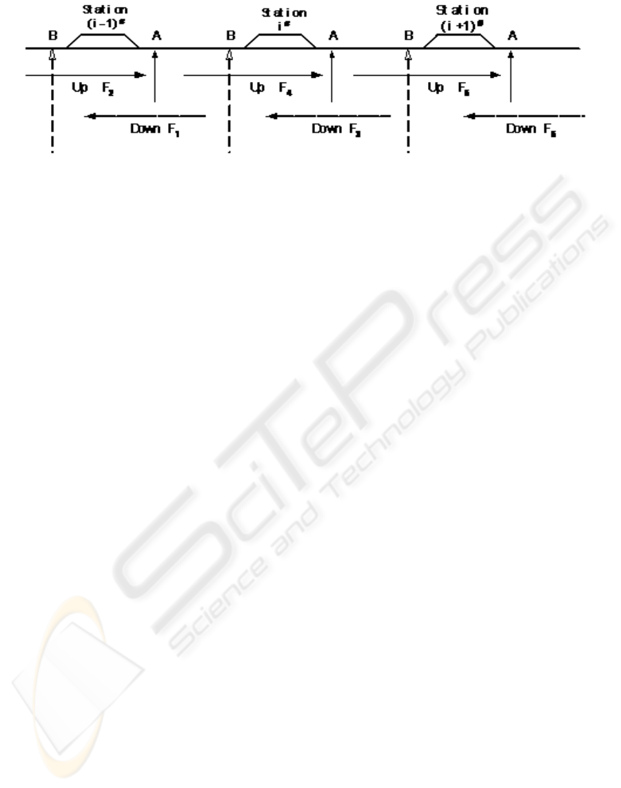
3.3 Using Different Frequencies
Alternatively in Different Stations
As shown in figure 1, every three stations use a
frequency group, to avoid common frequency
interference between stations. Each station has two
radios, one is used for up running direction, and the
other for down running direction, with two different
frequencies for each running direction respectively.
For example, frequency F
2
, F
4
, F
6
are used for up
running direction, and F
1
, F
3
, F
5
for down running
direction.
The frequency used for a train to communicate
with the next station can be pre-stored in a balise.
When an outbound train passes the balise, the
onboard interrogator will pick up the frequency
information from the balise and pass it to the
onboard control equipment of RBCS, which will
accordingly set the frequency of the onboard radio
to the new value.
ANALYSIS OF THE ARCHITECTURE AND RELIABILITY OF DATA TRANSMISSION NETWORK USED FOR
RADIO BASED CAB SIGNALING SYSTEM
395
3.4 Addressing Mode
The radio data transceiver used for RBCS works in
addressing mode, because all the radio stations
within the station area use the same frequency.
Therefore, the network address of the radio should
be included in the data frame. When a data
transceiver receives a data frame, it will compare the
address contained in the frame with its own address.
If two addresses match, the data frame will be
passed to the main controller for further processing;
otherwise the data frame will be rejected.
3.5 Data Frame Collision and
Communication Jam
Data frame collision can be avoided by adopting
time multiplexing and communication protocol. The
communication protocol will put strict constraint on
the time slot, the communication sequence of the
time slot, as well as the master-slave relationship
between the station radio and the onboard radio, in
order to guarantee the orderly communication
between station and train. During communication,
the onboard radio and the station radio may be
deadlocked for some reasons. In order to avoid the
interruption of the communication, overtime
detection circuit is designed to reset the radio.
3.6 Using Changeable Data Frame
The information transmitted by RBCS is divided
into three classes. Class I includes the basic train
control information; Class II includes the number of
the route for train receiving/departure, train number,
train actual speed and maximum allowed speed,
train position, etc. These above two classes of
information are vital train control information.
Furthermore, if permitted by time delay. The third
class of non-vital information used for the
engineering department, communication and
signaling department as well as locomotive
department can be transmitted. Therefore, different
frame format with long, medium and short length
can be chosen according to different requirements.
4 RELIABILITY OF RADIO DATA
TRANSMISSION
Because RBCS is used as a warrant for train
operation on main lines, its reliability, availability,
maintainability and safety (RAMS) is very important.
The transformation from TBTC to CBTC, is actually
the transformation of information transmission
channel. Therefore, the unreliable factors caused by
the transformation should be properly addressed in
system design. In the approaching continuous RBCS,
following measures are adopted to guarantee the
reliability.
(1) Any transmitted information is constrained by
the limitation of target address. In RBCS, the
information is transmitted via radio channel in the
open space, therefore, each station and on-board
control equipment of RBCS must be assigned a
unique network address.
(2) Time stamp is used to guarantee the time
validity of the information. In RBCS, information is
transmitted on time division multiplexing basis,
which may be interfered or attacked intentionally or
unintentionally, therefore, time stamp is used in the
bi-directional communication between train and
station, namely, the sender of the information should
attach the transmitted information with a time stamp;
upon receiving the information, the receiver will
check the time stamp for time validity. If the time
stamp expires, the information is regarded as invalid
and will not be executed
(3) Train registration method. Any train in the
controlled area of the dispatcher is assigned a unique
train number according to traffic plan. The train
number is associated with a registration number. So,
only a registered train can perform valid information
Figure 1: Frequency distribution in RBCS
ICINCO 2004 - ROBOTICS AND AUTOMATION
396

transmission in the radio channel.
The three-dimension control puts a strict
constraint on the bi-directional communication,
namely, only when the information has qualified for
the three constraints of address, time stamp and
registration number can it be regarded as valid. In
the effective working area of RBCS, each train
occupies a fixed space at any time, and is assigned a
unique registration number.
5 CONCLUSION
The result of the field test of RBCS has proved that
the structure of the transmission network and the
reliability of RBCS can meet the requirement of
train control. The constitution of data transmission
network by such methods as dynamic network
organization, star shape network, alternative
frequency used for different stations, and addressing
mode is reasonable and practicable. The
three-dimension control technique proposed in the
paper can enhance the reliability remarkably.
REFERENCES
Wang Junfeng, 2001, Analysis about the Reliability of
Wireless Data Transmission for High Speed Train in
Strong Interference Environment, IEEE 54
TH
VEHICULAR TECHNOLOGY CONFERENCE, VTC
FALL 2001, VOLS 1-4, PROCEEDINGS, 168-172
Wang Junfeng, 2001, Research on the Application of
Interwoven Techniques to improve the Real Time
Performance of Transmitting Train Control
Information by Radio, Mobile Communication, No.2
pp38-40.
Wang Junfeng, 2001, Analysis of the Safety of Train
Control System for Qinghai-Tibet Railway, Journal of
Safety Science of China, Vol.11, No.5, pp53-57, 2001
Wang Junfeng, Zhang Yong et al, 2002, Research on the
Radio Based Cab Signalling System used for
Qinghai-Tibet Railway, Journal of Railways, Vol.24,
No.3, pp22-27
Wang Junfeng, Zhang Yong et al, 2003, Analysis of the
Safety of The Train Control System of Qinghai-Tibet
Line, Proceedings of WCRR2003, Edinburgh, UK.
ANALYSIS OF THE ARCHITECTURE AND RELIABILITY OF DATA TRANSMISSION NETWORK USED FOR
RADIO BASED CAB SIGNALING SYSTEM
397
