
AVOIDING VISUAL SERVOING SINGULARITIES USING A
COOPERATIVE CONTROL ARCHITECTURE
N. Garc
´
ıa, C. P
´
erez, L. Pay
´
a, R.
˜
Neco, J.M. Sabater, J. M. Azor
´
ın
Dept. Ingenier
´
ıa de Sistemas Industriales. Universidad Miguel Hern
´
andez.
Avd. de la Universidad s/n. Edif. Torreblanca. 03202 Elche (Spain)
Keywords:
Visual servoing, control, sensors, computer vision, robotics.
Abstract:
To avoid the singularities of an image-based visual control of an industrial robot (Mitsubishi PA-10), a simple
and efficient control law which combines the information of two cameras in a cooperative way has been devel-
oped and tested. One of this cameras is rigidly mounted on the robot end-effector (eye-in-hand configuration)
and the other one observes the robot within its workspace (eye-to-hand configuration). The system architecture
proposed allows us to control the 6 dof of an industrial robot when typical problems of image-based visual
control techniques are produced.
1 INTRODUCTION
Nowadays, the great majority of robot population op-
erates in factories where the work environment is
structured and previously well-known. The applica-
tion of a robot to carry out a certain task depends, in a
high percentage, on the previously knowledge about
the work environment and object placement. This
limitation is due to inherent lack of sensory capability
in contemporary commercial industrial robots. It has
been long recognized that sensor integration is funda-
mental to increase the versatility and application do-
main of robots. One of these sensor systems is Com-
puter Vision.
Computer Vision is a useful robotic sensor since it
mimics the human sense of vision and allows for non
contact measurement of the work environment. In-
dustrial robot controllers with fully integrated vision
systems are now available from a large number of sup-
pliers. In these systems, visual sensing and manipu-
lation are typically integrated in an open-loop mode,
looking then moving. The precision of the resulting
operation depends directly on the accuracy of the vi-
sual sensor and the robot end-effector.
An alternative solution for the position and motion
control of an industrial manipulator evolved in un-
structured environments is to use the visual informa-
tion in a feedback loop. This robot control strategy
is called visual servo control or visual servoing. Vi-
sual servoing systems have recently received a grow-
ing interest, as the computational power of commer-
cially available computers became compatible with
real time visual feedback(B. Espiau, 1992)(Hutchin-
son et al., 1996).
During the last years, position or image based vi-
sual servoing systems, systems with different archi-
tectures (a camera or multiples cameras), stability
problems, calibration limitation, etc, have been stud-
ied. In particular, many image based visual ser-
voing systems have been developed basically with
two types of architecture: eye-in-hand configura-
tion(Garcia et al., 2002), when the camera is rigidly
mounted on the robot end-effector or eye-to-hand
configuration(R. Horaud and Espiau, 1998) when the
camera observes the robot within its work space.
The first approximation of using two cameras
in eye-in-hand/eye-to-hand configurations were pre-
sented in the work of (Marchand and Hager, 1998).
The system proposed used two task controlled by a
camera mounted on the robot and a global camera to
avoid obstacles during a 3D task. Then, in the paper
reported by (Flandin et al., 2000) a system for inte-
gration a fixed camera and a camera mounted on the
robot end-effector is presented. One task is used to
control the translation dof of the robot with the fixed
camera while other task is used to control the in eye-
in-hand camera orientation. In this paper, an image
based visual servo control of a 6 dof industrial robot
manipulator with a cooperative eye-in-hand/eye-to-
hand configuration is presented. In Section 2, the the-
162
García N., Pérez C., Payá L., Ñeco R., Sabater J. and Azorín J. (2004).
AVOIDING VISUAL SERVOING SINGULARITIES USING A COOPERATIVE CONTROL ARCHITECTURE.
In Proceedings of the First International Conference on Informatics in Control, Automation and Robotics, pages 162-168
DOI: 10.5220/0001134201620168
Copyright
c
SciTePress
oretical background of an image based visual servo-
ing system with eye-in-hand configuration and with
eye-to-hand configuration is described. In Section 3,
the control architecture of a cooperative image-based
visual servoing system is presented. In the last sec-
tion, some experimental results of this control scheme
are shown.
2 THEORETICAL BACKGROUND
In this section a short description of the theoretical
background of eye-in hand and eye-to-hand image-
based visual servoing approach will be described.
Moreover, this section is used to introduce the nota-
tion shown along the paper.
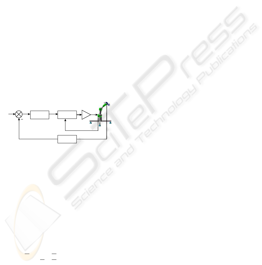
2.1 Eye-in-hand configuration
In this section, fundamentals about image-based vi-
sual servoing with eye-in-hand configuration is pre-
sented. This category of visual servoing is based on
the selection of a set s of visual features that has to
reach a desired value s*(Figure 1).
Power
Amplifiers
Joint
Controller
Image features
Extraction
Controller
Reference
Features
Current
Features
s*
s
Figure 1: Image-based visual servoing with eye-in-hand
configuration.
It is well known that the Image Jacobian L, also
called interaction matrix, relates the image features
changes with the camera velocity screw:
˙
s = L v (1)
where v = (V
T
, ω
T
) is the camera velocity screw
(V and ω represent its translational and rotational
component respectively). Using a classical perspec-
tive projection model with an intrinsic parameters ma-
trix A, and if x
i
, y
i
are the image coordinates of the
feature selected s
i
, then L is computed from:
L = A
h
−
1
Z
i
0
x
i
Z
i
x
i
y
i
−(1 + x
2
i
) y
i
0 −
1
Z
i
y
i
Z
i
1 + y
2
i
−x
i
y
i
−x
i
i
where Z
i
is the depth of the corresponding point in
the camera frame.
The great majority of references about control
schemes compute the camera velocity sent to the
robot controller (or directly the robot joints velocity,
by introducing the robot jacobian express in the cam-
era frame):
v = −λ L
+
(s − s
∗
) (2)
where λ may be as simple as a proportional gain
(B. Espiau, 1992), or a more complex function used
to regulate s to s
∗
(optimal control, non-linear control,
etc.), and L
+
is the pseudo-inverse of L.
As a general framework for sensor-based control
of robots, the task function approach (C. Samson and
Espiau, 1991) has been used:
e = L
+
(s − s
∗
) (3)
It is well known that in the task function approach, a
sufficient condition to ensure global asymptotic sta-
bility of the system is:
L
+
L(s
i
, Z
i
) > 0
In practice, three different cases of possible choices
for L
+
have been considered(Chaumette, 1998):
• It is numerically estimated during the camera mo-
tion without taking into account the analytical form
given by (2).
• It is constant and determined during off-line step
using the desired value of the visual features and
an approximation of the depth at the desired camera
pose. Stability condition is now ensured only in a
neighborhood of the desired position.
• 3. It is now update at each iteration of the control
law using in (2) the current measure of the visual
features and an estimation of the depth of each con-
sidered point. The depth can be obtained from the
knowledge of a 3D model of the object(DeMenthon
and Davis, 1992).
It is well known that the performance of image vi-
sual servoing system is generally satisfactory, even in
the presence of important camera or hand-eye calibra-
tion errors (Espiau, 1993). However, the following
stability and convergence problems may be occurred:
- Image jacobian may become singular during the
servoing, which of course leads to unstable behav-
ior.
- Local minima may be reached owing to the exis-
tence of unrealizable image motions.
- The image features go out of the image plane dur-
ing the control task
2.2 Eye-to-hand configuration
In this section, fundamentals about image based vi-
sual servoing with eye-to-hand configuration are pre-
sented. The camera used in this eye-to-hand configu-
ration observes a moving robot gripper. This category
of visual servoing is based on the selection of a set
s of visual features that has to reach a desired value
AVOIDING VISUAL SERVOING SINGULARITIES USING A COOPERATIVE CONTROL ARCHITECTURE
163
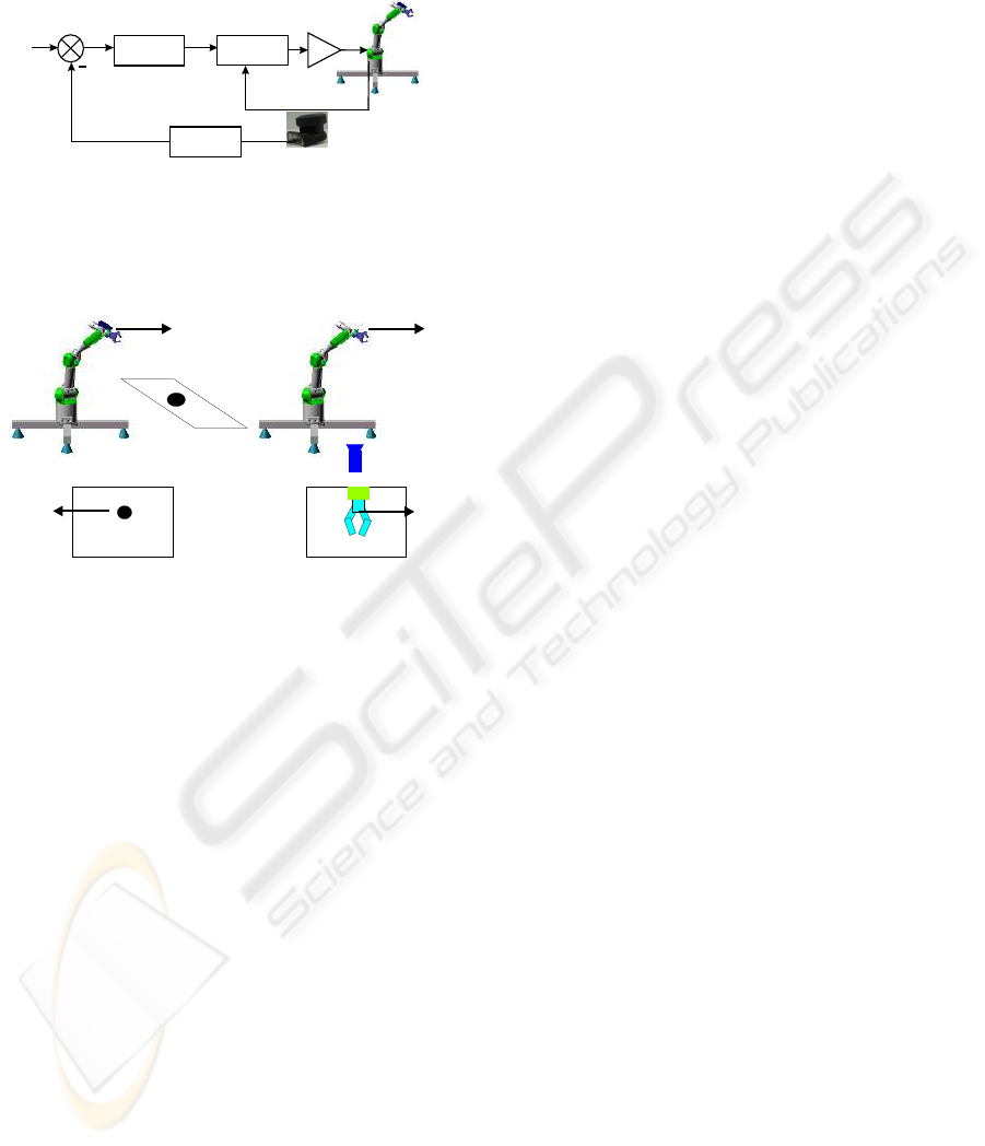
s* (Figure 2). From the movement of image features
point of view, the relation between eye-in-hand and
eye-to-hand configurations is shown in Figure 3.
Power
Amplifiers
Joint
Controller
Image features
Extraction
Controller
Reference
Features
Current
Features
Camera
Sony EVI-31D
s*
s
Figure 2: Image-based visual servoing with eye-to-hand
configuration.
Camera
Camera
Image Plane Image Plane
Eye-in-hand configuration
Eye-to-hand configuration
Figure 3: Relation between eye-in-hand and eye-to-hand
configurations.
It’s necessary to stress the fact that, in the eye-to-
hand configuration, the image jacobian or interaction
matrix has to take into account the mapping from the
camera frame onto the robot control frame. If we de-
note (R, t) this mapping (R being the rotational ma-
trix and t the translational vector), the eye-to-hand ja-
cobian L
ETH
is related to the eye-in-hand one L
EIH
by:
L
ETH
= −L
EIH
·
R −R · S(−R
T
t)
0 R
¸
(4)
where S(a) is the skew symmetric matrix associated
with vector a. The control law is identical to (2).
3 COOPERATIVE
EYE-IN-HAND/EYE-TO-HAND
SYSTEM
Combining several sensory data is also an important
issue that has been studied considering two funda-
mentally different approaches. In the first one, the dif-
ferent sensors are considered to complementary mea-
sure of the same physical phenomena. Thus, a sen-
sory data fusion strategy is used to extract a perti-
nent information from the multiple sensory data. The
second control approach consists of selecting, among
the available sensory signals, a set of pertinent data,
which is then servoed. The two approaches will be
referred as sensory data fusion and sensory data se-
lection respectively.
A typical example of sensory data fusion is stereo
vision. With this approach, two images provided by
two distinct cameras are used to extract a complete
Euclidean information on the observed scene. On the
other hand, sensory data selection is used when all
the different data no provide the same quality of in-
formation. In this case one can use data environment
models in order to select the appropriate sensor and to
switch control between sensors.
The approach to cooperative eye-in-hand/eye-to-
hand configuration shown in this paper is a clearly
case of multi sensory robot control(Malis et al., 2000).
It does not pertain to sensory data fusion because we
assume that the sensors may observe different physi-
cal phenomena from which extracting a single fused
information does not make sense. It neither pertains
to sensory data selection because we consider poten-
tial situations for which it is not possible to select a set
of data that would be more pertinent than others. Con-
sequently, the proposed approach addresses a very
large spectrum of potential applications, for which the
sensory equipment may be disparate and complex. As
an improvement over previous approaches, there is
no need to provide a model of the environment that
would be required to design a switching or fusion
strategy.
The robot is supposed to be controlled by a six
dimensional vector T
E
representing the end-effector
velocity, whose components are supposed to be ex-
pressed in the end-effector frame. There are two
cameras, one of them rigidly mounted on the robot
end-effector(eye-in-hand configuration) and the other
one observing the robot gripper(eye-to-hand configu-
ration). Each sensor provides an n
i
(n
i
> 6) dimen-
sional vector signal s
i
. Let s = [s
EIH
s
ETH
]
T
be the
vector containing the signals provided by the two sen-
sors. Using the task function formalism (C. Samson
and Espiau, 1991), an error function e = C(s − s
∗
)
can be defined as:
e =
·
e
EIH
e
ETH
¸
=
=
·
C
EIH
C
ETH
¸µ·
s
EIH
s
ETH
¸
−
·
s
∗
EIH
s
∗
ETH
¸
(5)
where C = [C
EIH
C
ETH
]
T
is a full rank matrix,
of dimension m × n
i
(where m must be equal to dof
to be controlled in this case m = 6), which allows to
take into account information redundancy.
ICINCO 2004 - ROBOTICS AND AUTOMATION
164
An interaction matrix is attached to each sensor,
such that:
˙
s
EIH
= L
EIH
T
CE
EIH
T
E
(6)
˙
s
ETH
= L
ETH
T
CE
ETH
T
E
where T
CE
is the transformation matrix linking sen-
sor velocity and the end effector velocity, in the case
of eye-in-hand configuration will be constant and on
the other case(eye-to-hand configuration) will be vari-
able. The equation (6) can be expressed as a matrix:
˙
s =
·
˙
s
EIH
˙
s
ETH
¸
=
·
L
EIH
0
0 L
ETH
¸·
T
CE
EIH
T
CE
ETH
¸
T
E
= L
T
· T
CE
· T
E
(7)
The time derivative of the task function (5), consider-
ing C and s* constant, is:
˙e = C˙s = CL
T
T
CE
T
E
(8)
A major concern in designing a task function based
controller is to select a suitable constant matrix C,
while ensuring that the matrix CL
T
T
CE
T
E
has a
full rank.
In this paper, C is designed as a function of the
pseudo-inverse of L
T
and T
CE
.
C = [k
1
T
−1
CE
EIH
L
+
EIH
k
2
T
−1
CE
ETH
L
+
ETH
] (9)
where k
i
is a positive weighting factor such that
P
2
i=1
k
i
= 1 . If for each sensor a task function
(where i = 1 is referred to eye-in-hand configura-
tion and i=2 to eye-to-hand configuration) is consid-
ered, then the task function of the entire system is a
weighted sum of the task functions relative to each
sensor:
e = C(s − s
∗
) =
2
X
i=1
k
i
· e
i
=
=
2
X
i=1
k
i
· C
i
(s
i
− s
∗
i
) (10)
The design of the two sensors combination simply
consists of selecting the positive weights k
i
. This
choice is both task and sensor dependent. The weights
k
i
can be set according to the relative precision of
the sensors, or more generally to balance the velocity
contribution of each sensor. Also a dynamical setting
of k
i
can be implemented.
A simple control law can be obtained by imposing
the exponential convergence of the task function to
zero:
˙e = −λe ⇒ CL
T
T
CE
T
E
= −λe (11)
where λ is a positive scalar factor which tunes the
speed of convergence:
˙e = −λ(CL
T
T
CE
)
−1
e (12)
Taking into account (9), it can be demonstrated that
(CL
T
T
CE
)
−1
is equal to the identity:
(CL
T
T
CE
)
−1
= (
2
X
i=1
k
i
T
−1
CE
i
L
+
i
L
i
T
CE
i
)
+
=
= (
2
X
i=1
k
i
I
6
)
+
= I
6
(13)
So, if C is setting to (9) and each subsystem is stable,
then (CL
T
T
CE
)
−1
> 0 and the task function con-
verge to zero and, in the absence of local minima and
singularities, so does the error s - s*. In this case, this
control law can be used to drive back the robot to the
reference position.
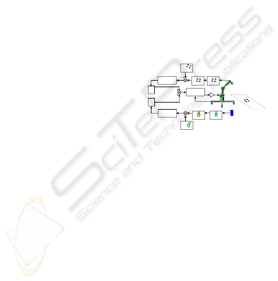
In Figure 4, a control scheme of the general archi-
tecture proposed can be seen. To implement it, a soft-
ware function to give the corresponding values to k
1
and k
2
is used.
Camera
Camera
Features
Extraction
Features
Extraction
Reference
Features
Reference
Features
Power
Amplifiers
Joint
Controller
Controller
Controller
K
2
K
1
q
1
q
2
q
Figure 4: General architecture of the controller proposed.
4 EXPERIMENTAL RESULTS
Experimental results has been carried out using a 7
axis redundant Mitsubishi PA-10 manipulator (only 6
of its 7 dof have been considered). The experimental
setup used in this work also include one camera(JAI
CM 536) rigidly mounted in robot endeffector, one
camera(EVI 31D) observing the robot gripper, some
experimental objects and a computer with a Matrox
Genesis vision board and other pc with the PA-10
controller board. An RPC link between the robot con-
troller and the computer with the vision board for syn-
chronization tasks and data interchange has been im-
plemented. The whole experimental setup can be seen
in Figure 5.
It’s obvious that the performance of the system pro-
posed depends on the selection of the weights k
i
. Be-
fore giving the corresponding value to k
i
some rules
have been taking into account to avoid typical prob-
lems of image-based visual servoing approaches like
task singularities, features extraction errors, disap-
pearance of features from the image plane and so on.
AVOIDING VISUAL SERVOING SINGULARITIES USING A COOPERATIVE CONTROL ARCHITECTURE
165

To do this, a checking routine is executed and if one
of the problems described before are produced, the
corresponding value of k
i
will set to zero. Obviously,
the system fails if the problems happens in the two
configurations at the same time.
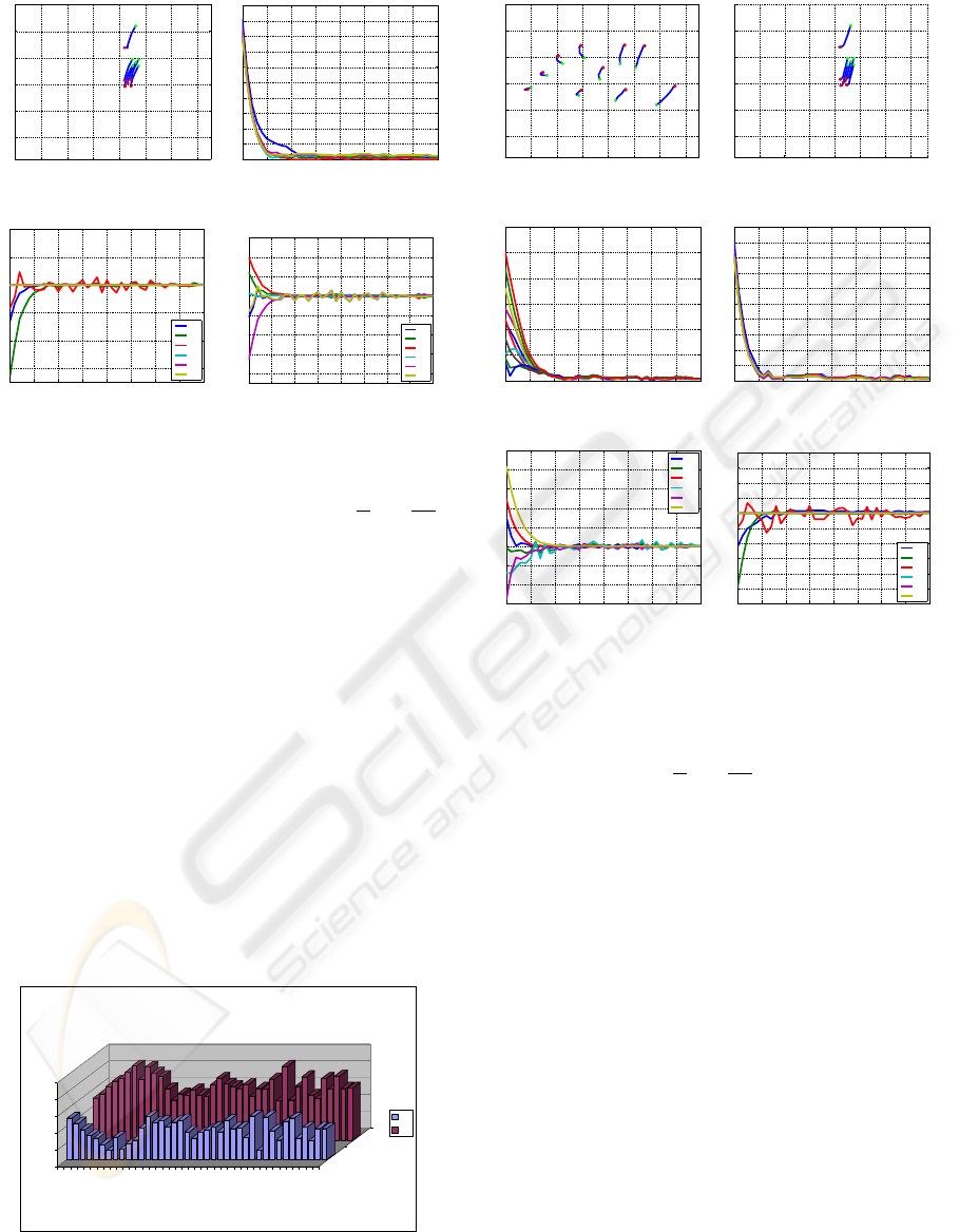
Exhaustive number of experiments have been made
with different weights(Figure 6). In Figure 7 and Fig-
ure 10, the results with (K
1
= 1, K
2
= 0 only
the camera in eye-in-hand configuration is used and
K
1
= 0, K
2
= 1 only the camera in eye-to-hand con-
figuration is used)are presented. Observing them, we
can realize that each system is stable and the error is
zero excepted by the noise of features extraction.
PA-10
CAMERA JAI CM536
EYE-IN-HAND
CAMERA SONY EVI D31
EYE-TO-HAND
Figure 5: Experimental setup.
0 0,2 0,4 0,6 0,8 1
K1 AND K2
EXP 1
EXP 2
EXP 3
EXP 4
EXP 5
EXP 6
EXP 7
EXPERIMENTS
EXPERIMENTS WITH DIFFERENTS VALUES OF K1 AND K2
K1
K2
ONLY EYE-IN-HAND
ONLY EYE-TO-HAND
Figure 6: Experiments with different values of k
1
and k
2
.
The results of all the experiments show that the
control system proposed is stable and independent to
the values of k
i
. This conclusion corroborates the
stability analysis presented at the end of Section 3.
Assuring that each system is stable, the cooperative
control system allow us to modify the magnitud of k
i
without risk of making the system unstable.
For this reason, experiments with variable values
of k
i
have been carried out. To compute k
i
in each
sample time, the following function that depends on
the relative image error is used:
k
1
=
e
rel
EIH
e
rel
EIH
+ e
rel
ETH
(14)
k
2
=
e
rel
ETH
e
rel
EIH
+ e
rel
ETH
(15)
where:
e
rel
i
=
s
i
(t) − s
∗
i
s
i
(0) − s
∗
i
(16)
Note that e
rel
EIH
is computed when i = 1 and then
is normalized dividing it by the number of image fea-
tures. In the same way, e
rel
ETH
is obtained.
The key idea of using this function is that the con-
trol contribution due to one of the cameras has more
effect when its image features are far from their ref-
erence position. With this formulation of variable
k
i
, the local minima problems are avoided since the
change in the weights k
i
will bring the system away
from it. So we can assure that e = 0 if and only if
e
i
= 0 ∀ i. In Figure 9, the values of k
1
and k
2
during
the control task can be seen. In Figure 11, the results
of using a variable value of the weights are shown.
0 100 200 300 400 500 600 700 752
0
100
200
300
400
500
582
u (pixels)
v (pixels)
(a) Image plane
0 5 10 15 20 25 30 35 40
0
20
40
60
80
100
120
Iterations number
(b) Errors ks
i
-s
∗
i
k
0 5 10 15 20 25 30 35 40
−0.2
−0.15
−0.1
−0.05
0
0.05
0.1
0.15
0.2
0.25
0.3
Iterations number
ω
ω
x
ω
y
ω
z
(c) Rotation speed
0 5 10 15 20 25 30 35 40
−0.05
0
0.05
0.1
0.15
0.2
Iterations number
V
V
x
V
y
V
z
(d) Translation speed
Figure 7: Results with K
1
= 1, K
2
= 0. Only the results
of the camera in eye-in-hand configuration is shown. The
translation and rotation speeds are measured in
m
s
and
deg
s
.
5 CONCLUSION
The cooperative visual servoing proposed in this pa-
per have been designed to make more efficient the
classical imaged based visual servoing systems. In
all the experimental results presented, the position-
ing accuracy of the architecture presented in this pa-
ICINCO 2004 - ROBOTICS AND AUTOMATION
166
0 100 200 300 400 500 600 700
0
100
200
300
400
500
u (pixels)
v (pixels)
(a) Image plane
0 5 10 15 20 25 30 35 40
0
10
20
30
40
50
60
70
80
90
100
Iterations number
(b) Errors ks
i
-s
∗
i
k
0 5 10 15 20 25 30 35 40
−0.3
−0.2
−0.1
0
0.1
0.2
Iterations number
V
x
V
y
V
z
ω
x
ω
y
ω
z
(c) Rotation speed
0 5 10 15 20 25 30 35 40
−0.8
−0.6
−0.4
−0.2
0
0.2
0.4
0.6
Iterations number
joint velocities
jv
1
jv
2
jv
3
jv
4
jv
5
jv
6
(d) Translation speed
Figure 8: Results with K
1
= 0, K
2
= 1. Only the results
of the camera in eye-to-hand configuration is shown. The
translation and rotation speeds are measured in
m
s
and
deg
s
.
per is improved and also problems like local min-
ima, task singularities, features extraction errors are
avoided. Moreover, the architecture proposed, per-
mits also to use several sensors (cameras, force sen-
sors, etc.). Now, we are testing different functions to
give values to k
i
.
ACKNOWLEDGEMENT
This work has been supported by the Spanish Govern-
ment through the ’Comision Interministerial de Cien-
cia y Tecnologa’ (CICyT) through project ”Modelado
de espacios virtuales para entrenamiento de sistemas
teleoperados en entornos dinmicos” DPI2001-3827-
C02-02
0,0000
0,2000
0,4000
0,6000
0,8000
1,0000
1 3 5 7 9 11 13 15 17 19 21 23 25 27 29 31 33 35 37 39
K1
K2
EXPERIMENT WITH VARIABLE VALUES OF K1 AND K2
K1
K2
Figure 9: Experiments with variable values of k
1
and k
2
.
0 100 200 300 400 500 600 700 752
0
100
200
300
400
500
582
Iterations number
(a) Image plane
0 100 200 300 400 500 600 700 768
0
100
200
300
400
500
582
Iterations number
(b) Image plane
0 5 10 15 20 25 30 35 40
0
20
40
60
80
100
120
Iterations number
(c) Errors ks
i
-s
∗
i
k
0 5 10 15 20 25 30 35 40
0
10
20
30
40
50
60
70
80
90
100
Iterations number
(d) Errors ks
i
-s
∗
i
k
0 5 10 15 20 25 30 35 40
−0.6
−0.4
−0.2
0
0.2
0.4
0.6
0.8
1
Iterations number
V
x
V
y
V
z
ω
x
ω
y
ω
z
(e) Rotation speed
0 5 10 15 20 25 30 35 40
−0.25
−0.2
−0.15
−0.1
−0.05
0
0.05
0.1
0.15
0.2
Iterations number
V
x
V
y
V
z
ω
x
ω
y
ω
z
(f) Translation speed
Figure 10: Results with variable values of K
1
and K
2
. Fig-
ures (a,c,e) are the results of the camera in eye-in-hand con-
figuration and figures (b,d,f) are the same for the camera
in eye-to-hand configuration. The translation and rotation
speeds are measured in
m
s
and
deg
s
.
REFERENCES
B. Espiau, F. Chaumette, P. R. (1992). A new approach to
visual servoing in robotics. IEEE Trans. Robotics and
Automation, 8(3):313–326.
C. Samson, M. L. and Espiau, B. (1991). Robot Control:
the Task Function Approach. volume 22 of Oxford
Engineering Science Series.Clarendon Press., Oxford,
UK, 1st edition.
Chaumette, F. (1998). Potential problems of stability and
convergence in image-based and position-based visual
servoing. In Kriegman, D., Hager, G. ., and Morse, A.,
editors, The Confluence of Vision and Control, pages
66–78. LNCIS Series, No 237, Springer-Verlag.
DeMenthon, D. and Davis, L. S. (1992). Model-based ob-
ject pose in 25 lines of code. In European Conference
on Computer Vision, pages 335–343.
Espiau, B. (1993). Effect of camera calibration errors on
visual servoing in robotics.
Flandin, G., Chaumette, F., and Marchand, E. (2000). Eye-
in-hand / eye-to-hand cooperation for visual servoing.
AVOIDING VISUAL SERVOING SINGULARITIES USING A COOPERATIVE CONTROL ARCHITECTURE
167

In IEEE Int. Conf. on Robotics and Automation, vol-
ume 3, pages 2741–2746, San Francisco.
Garcia, N., Mamani, G., Reinoso, O., Nasisi, O., Aracil, R.,
and Carelli, R. (2002). Visual servo control of indus-
trial robot manipulator. In 15th IFAC World Congress
in Automation and Control, volume 1, Barcelona,
Spain.
Hutchinson, S. A., Hager, G. D., and Corke, P. I. (1996). A
tutorial on visual servo control. IEEE Trans. Robotics
and Automation, 12(5):651–670.
Malis, E., Chaumette, F., and Boudet, S. (2000). Multi-
cameras visual servoing. In IEEE International Con-
ference on Robotics and Automation, volume 4, pages
3183–3188, San Francisco, USA.
Marchand, E. and Hager, G. (1998). Dynamic sensor plan-
ning in visual servoing. In IEEE Int. Conf. on Robotics
and Automation, volume 3, pages 1988–1993, Leu-
ven,Belgium.
R. Horaud, F. D. and Espiau, B. (1998). Visually guided ob-
ject grasping. IEEE Trans. Robotics and Automation,
14(4):525–532.
ICINCO 2004 - ROBOTICS AND AUTOMATION
168
