
STRUCTURED INFORMATION PROCESSING FOR
SELF-OPTIMIZING MECHATRONIC SYSTEMS
∗
Thorsten Hestermeyer, Oliver Oberschelp
University of Paderborn, Mechatronic Laboratory Paderborn, Pohlweg 98, 33098 Paderborn, Germany
Holger Giese
University of Paderborn, Software Engineering Group, Warburger Strae 100, 33098 Paderborn, Germany
Keywords:
Self-Optimization, Mechatronics, Software Technology, Control Engineering, Artificial Intelligence, Recon-
figuration, Safety-Critical Systems.
Abstract:
Self-optimizing mechatronic systems are based on intrinsic controller systems whose complexity by far ex-
ceeds that of currently available systems. In addition to procedures taken from artificial intelligence, proce-
dures for a reconfiguration by means of appropriate design methods have to be integrated to fully implement
self-optimization features. Special importance falls to a networking of such complex controller systems for the
support of collaborative and emergent self-optimization. One main challenge lies in the safety-critical nature
of the systems that requires the resulting software along with the technical system to show a predictably cor-
rect behavior in spite of networking, reconfiguration, and integration of procedures from artificial intelligence.
The paper presents a concept for structuring and designing reconfigurable controller systems.
1 INTRODUCTION
Due to an increasing functionality of software-based
controller systems in recent mechatronic systems the
complexity of the information processing and thus the
number of errors increases accordingly. Further in-
creasing complexity is bound to result in a distinct
increase in the number of these problems unless they
are countered by a clear structuring of the systems to
be effected by an appropriate software support and au-
tomatized verification procedures.
This statement is even more true in the case of
cognitive abilities going to be integrated into fu-
ture systems where variable environmental conditions
and changes in their own behavior are accounted for
by self-optimization in the information processing.
Here a reconfiguration of control components is of
great importance. The safety-critical nature of self-
optimizing systems (Storey, 1996) causes the prob-
lems of ”classical” mechatronic systems to be by far
exceeded by additional complexity and possible dan-
gers resulting from interlinking reconfigurable sub-
∗
This work was developed in the course of the ”Col-
laborative Research Center 614 - Self-Optimizing Concepts
and Structures in Mechanical Engineering” - University of
Paderborn, and was published on its behalf and funded by
the Deutsche Forschungsgemeinschaft.
systems and integrating procedures taken from arti-
ficial intelligence. In the process it is compulsory to
employ adequate design methods and tools.
2 OPERATOR-CONTROLLER
MODULE (OCM)
The information-processing unit of a mechatronic
system has to perform a multitude of functions: con-
trol code working in quasi-continuous mode controls
motions in the plant, error-analysis software monitors
the plant in view of occurring malfunctions, adapta-
tion algorithms adapt the control to altered environ-
mental conditions, different systems are interlinked,
to name but a few of these functions.
These various tasks access the actuators of the
plant more or less directly. Fig. 1 proposes a new
structure of the information processing of a mecha-
tronic function module (MFM - cf. e.g. (Oberschelp
et al., 2002)) that resulted from practical experiences
and combines the approaches presented in (Naumann
and Rasche, 1998) and (Naumann, 2000) with con-
cepts from (Hestermeyer et al., 2001) and (Ober-
schelp et al., 2002). The OCM set-up orientates itself
by the kind of effect on the technical system:
230
Hestermeyer T., Oberschelp O. and Giese H. (2004).
STRUCTURED INFORMATION PROCESSING FOR SELF-OPTIMIZING MECHATRONIC SYSTEMS.
In Proceedings of the First International Conference on Informatics in Control, Automation and Robotics, pages 230-237
DOI: 10.5220/0001138102300237
Copyright
c
SciTePress
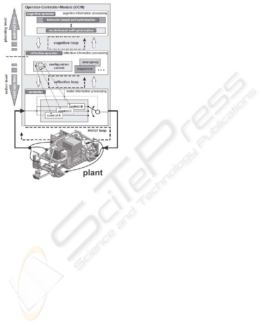
Figure 1: OCM structure
1. On the lowest level of the OCM there is the con-
troller. This innermost loop processes measure-
ments and produces control signal. It directly ef-
fects the plant. It can therefore be called ”motor”
loop. Software processing on this level works in
a quasi-continuous mode, i.e., measured values are
read in, processed, and output continuously and un-
der hard real-time conditions. The controller can be
made up of several controllers, with the possibility
to switch between them. The switch is done in one
step; fade-over mechanisms and the like are again
integrated in a separate controller element (see Sec-
tion 3).
2. The controller is complemented by a reflective op-
erator in which monitoring and controlling rou-
tines are executed. The reflective operator does
not access the actuators of the system directly but
modifies the controller. In certain circumstances it
can also switch between different controller con-
figurations. The reflective operator operates very
much in an event-oriented manner. On this level,
though, there are also other quasi-continuous func-
tions, such as continuous adaptation algorithms or
so-called watchdogs. Because it is tightly linked to
the controller, the reflective operator has also to op-
erate under hard real-time constraints. The reflec-
tive operator, connecting element to the cognitive
level of the OCM, provides an interface between
those elements that are apt for real-time operation
resp. operating in soft real time and the controller.
It filters the incoming signals and inputs them to
the subordinated levels.
3. The topmost level of the OCM is occupied by the
cognitive operator. On this level the system can
gather information on itself and its environment by
applying various methods such as learning, use of
knowledge-based systems, model-based optimiza-
tion, and the like; it can employ them for improving
its own behavior. Moreover, one can think of other
cognitive functions. The present paper will confine
itself to local self-optimization. This optimizing in-
formation processing can roughly be divided into
model-based and behavior-based self-optimization.
Model-based optimization allows an optimization
that is predictive and decoupled in time from the
real system. The behavior-based optimization com-
prises functions for planning and evaluating the
current objectives (cf. (Oberschelp et al., 2002) and
(Hestermeyer and Oberschelp, 2003)). While both
the controller and the reflective operator are subject
to hard real-time constraints the cognitive operator
can also operate asynchronously to the real time.
Of course it has to respond within a certain time
limit; otherwise, due to altered environmental con-
ditions, self-optimization would not find utilizable
results. So the cognitive operator is subject to soft
real time.
To sum things up, one can detect two distinct levels
of separation: on the one hand, information process-
ing is divided into two loops affecting the system, one
directly and the other only indirectly. This division re-
flects the one that distinguishes between operator and
controller. On the other hand, one can distinguish be-
tween hard and soft real time constraints. This classi-
fication sets the cognitive operator apart from the re-
flective one and the controller. As the level of separa-
tion is chosen according to the task we propose three
separate elements.
3 RECONFIGURABLE BLOCK
DIAGRAMS
This section deals with the use of block-diagram rep-
resentation for the purpose of defining reconfigurable
systems that are the basis for structure-variable self-
optimizing systems. In general, block diagrams serve
for an abstract modelling of technical systems. In
STRUCTURED INFORMATION PROCESSING FOR SELF-OPTIMIZING MECHATRONIC SYSTEMS
231

many CAE tools they are the basis for an abstract
modelling. Block diagrams have their origin in con-
trol engineering where they serve the purpose of
graphically representing mathematical transfer func-
tions. As their name indicates, block diagrams are
composed of blocks. A block encapsulates a func-
tion or a behavior. In most cases this behavior is
described mathematically, e.g., as differential equa-
tions in a state-space representation of the dynamics.
Equally possible is a description by physical elements
such as in multibody system models. In this process
the mathematics is derived automatically by means
of automated transformation methods, such as New-
ton or Lagrange. Between the individual blocks there
are interconnections or links that can have the shape
of direct or non-direct links. With direct links data
are exchanged whereas non-directed ones often de-
scribe functional relations or physical links, such as
a link between mass and spring in multibody system
representation. Hierarchical block diagrams broaden
this approach by classifying several blocks into hier-
archies which may themselves comprise other hierar-
chies. This allows a structured design and reduces the
overall complexity of a block diagram:
Figure 2: Block diagrams in the CAE tools CAMeL and
MATLAB
Fig. 2 displays typical block diagrams developed
with the tools CAMeL and MATLAB. The respective
left-hand part of the windows shows the tree struc-
tures while the right-hand side displays the topology
of a level. The topology of hierarchical block dia-
grams can be displayed as a tree, with its leaves repre-
senting the behavior resp. the function and the nodes
describing the interconnections and the structure of
the system (Fig. 3):
The distinction between structure (hierarchy) and
function (block) can be used to derive an integrated
representation of reconfiguration from the classical
block diagrams described above. In our context, a
reconfiguration is a change in the structure resp. sub-
Figure 3: Hierarchical block diagrams
structure of a system. It alters the topology of the
system; functions are added and/or interlinked anew.
Under the assumption that all functional blocks us-
able in a defined configuration are set and defined, a
reconfiguration will alter only hierarchical elements:
Figure 4: Reconfiguration on the topological level
Alteration of only one part of the system corre-
sponds to a change of one part of the topological tree,
under the important boundary condition that the inter-
faces of the exchanged hierarchical elements be com-
patible. Fig. 4 displays this principle for an exchange
of a hierarchical element. The element and all subor-
dinated components are exchanged in the process.
The boundary conditions to an exchange of hier-
archical elements, assuming that all components to
be switched have to exist and all interfaces have to
be compatible, can now be employed for the defi-
nition of a new hierarchical element describing dif-
ferent topologies. A hierarchical element can com-
prise different configurations in the shape of topolo-
gies and inner interconnections that are valid at vary-
ing times. The superordinated hierarchy does not no-
tice the change in the topology of the subordinated hi-
erarchy because the latter is described outwardly only
by its interfaces:
If the different topologies are seen as states of the
subordinated hierarchical element it makes sense to
ICINCO 2004 - SIGNAL PROCESSING, SYSTEMS MODELING AND CONTROL
232
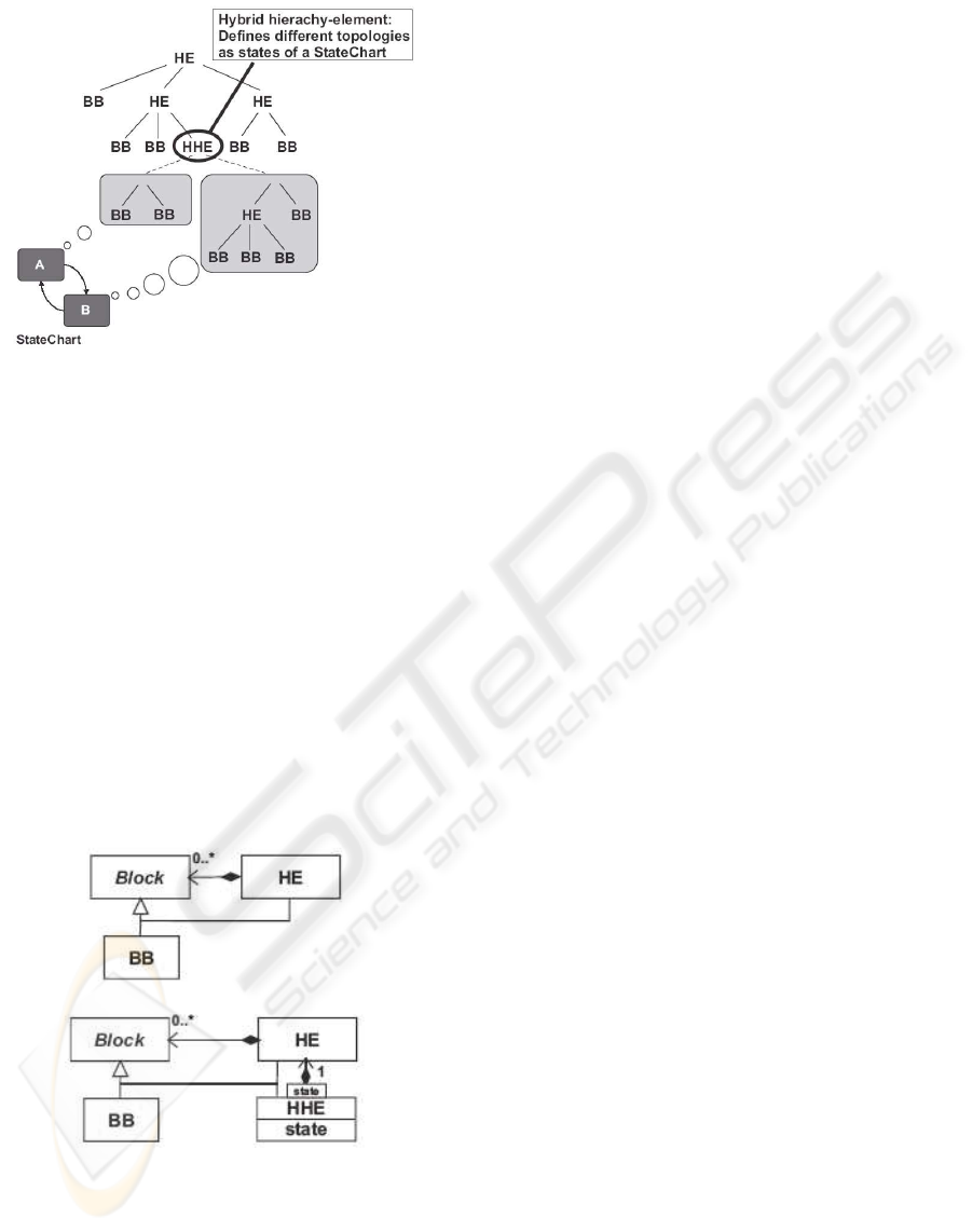
Figure 5: Hybrid hierarchical elements
control the change between the different topologies
by means of a state machine. With the help of State-
Charts (Harel, 1987) it is possible to specify all tran-
sition processes and to employ them as interfaces for
a reconfiguration. Combining a StateChart and a hi-
erarchical element leads to specific hybrid systems,
with the result of this combination of reconfigurable
hierarchical element and StateChart being named a
hybrid hierarchical element. A great advantage of
this approach lies in the fact that it includes as a spe-
cial case those classical, non-reconfigurable block di-
agrams, and this in the shape of a hybrid hierarchical
element with only one state. Thus it is possible to
design also reconfigurable systems according to well-
known methods:
Figure 6: Structure of the block interconnection without and
with reconfiguration
Fig. 6 visualizes the elements required for the in-
tegration model with and without reconfiguration as
well as their hierarchy by means of a UML class di-
agram (UML, 2003). In addition to the basic blocks
(BB) and the hierarchical elements (HE) in the model
without reconfiguration (Fig. 6, top) our integrated
model (Fig. 6, bottom) comprises also hybrid hierar-
chical elements (HHE). Basic blocks may e.g. be (hy-
brid) mathematical functions, but also inputs and out-
puts, especially interfaces to actuators and sensors. A
hierarchical element links any number of blocks of the
respective type and thus is a true likeness of the classi-
cal hierarchical block diagram. The additional hybrid
hierarchical elements with local, discrete states allow
also to employ one hierarchical element per state; this
makes possible an adequate representation of the re-
configuration of the block diagrams. Easy to oper-
ate, an HHE comprising only subordinated elements
of the HE and BB types that are limited to the case
of quasi-continuous elements resembles the usual ap-
proaches to the modelling of hybrid systems by means
of differential equations and automats (cf. (Henzinger
et al., 1995)). By offering the possibility to use such
HHE blocks several times over, the concept presented
outmatches other known approaches.
4 OCM ARCHITECTURES WITH
RECONFIGURATION
Section 3 elaborated on a systematic extension of
classical block diagrams to a kind with reconfigurable
parts by means of discrete switches. In the following
we will explain how to apply these concepts to OCM
architectures. In addition to hierarchy, the systems
are characterized by the information flow occurring
with every configuration. Information between the
elements of the integration model can be transported
via event channels, discrete or quasi-continuous sig-
nal channels and has been omitted in the model for
reasons of space. Furthermore this information flow
brings about direct and bidirectional links between the
inputs and outputs of the blocks. In the design of self-
optimizing mechatronic systems by means of recon-
figurable block diagrams, an OCM corresponds to a
coherent number of unambiguously allocated blocks
in such a manner that the entire block structure cor-
responds to a tree made up of OCM. The arrange-
ment of the different parts of the OCM makes up a
well-structured architecture if and only if the follow-
ing rules apply:
• All BB- and HE blocks that have a direct effect on
an actuator of the OCM or of a subordinated OCM
via signals in the workflow - and just these - have
to be allocated to the controller of the OCM.
• Concerning the distinction into reflective operator
and cognitive operator, the rule must hold that the
cognitive operator can affect the reflective operator
only in an event-driven manner and that it cannot
STRUCTURED INFORMATION PROCESSING FOR SELF-OPTIMIZING MECHATRONIC SYSTEMS
233
affect the controller at all, the reflective operator
having to stay capable of acting at all times even
without assistance by an active cognitive operator.
This means that the reflective operator has to be ca-
pable of acting autonomously to the degree that his
behavior is sufficient to ensure the OCM to operate
safely.
• As regards the interconnections between the com-
ponents of the different OCM, the rule must hold
that controllers are linked only to controllers of the
superordinated and subordinated OCM and reac-
tive operators only to the reactive ones of the su-
perordinated reactive operator and the subordinated
reactive ones. A similar structure with the cognitive
operators is useful but not compulsory.
The above limitation to well-structured architec-
tures gives the guarantee that the decoupling between
controller and reflective operator as well as that be-
tween reflective and cognitive operator correspond to
the architecture presented in Section 2 and that the
cognitive blocks will have no unsupervised direct ac-
cess to the controller. If one wants to realize the
required interconnection structure by means of the
above-described classical block diagrams one will en-
counter the following problem: a hierarchical decom-
position of all levels of the system (controller, re-
flective operator, cognitive operator) results in several
overlapping trees that cannot be represented by a sin-
gle tree like the one displayed in Fig. 6. We have here
the same problem that occurs in the software domain
if only one hierarchical decomposition dimension is
allowed (Tarr et al., 1999). In order to avoid this prob-
lem one will have to admit a well-structured multiple
referencing
2
for each OCM so that every level can ad-
equately describe its partial hierarchy:
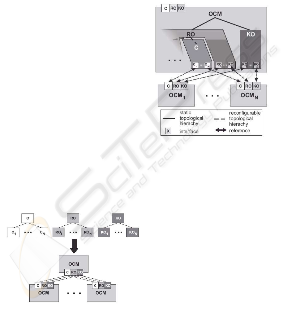
Figure 7: OCM with interfaces for all three levels
2
In contrast to the composition (”is contained”-relation).
In order to support multiple referencing every
OCM provides three separate interfaces C, RO, and
KO for controller, reflective operator, and cognitive
operator (cf. Fig. 7). Thus the required allocation
to block diagrams of the superordinated OCM can be
adequately described for the different levels:
Figure 8: OCM with reconfiguration
Fig. 8 illustrates how the three levels of controller,
reflective operator, and cognitive operator from Fig. 1
can be integrated in one single hierarchical block di-
agram. The different configurations of the controller
are mapped to individual trees. The reflective opera-
tor assumes the task of coordinating the switches be-
tween the different configurations of the controller.
The behavior of the reflective operator itself is de-
scribed by a state machine which, in addition to its
conditions and side effects, disposes of a reconfig-
urable structure of quasi-continuous blocks so that,
for instance, quasi-continuous blocks required for
purposes of diagnosis can be used in the reflective op-
erator if the need arises. In contrast to the tight inter-
lacing between controller and reflective operator, the
cognitive operator makes up a separate tree whose in-
terconnection with the reflective operator must be re-
stricted to event channels. Moreover, Fig. 8 illustrates
the way the three interfaces of the respective subordi-
nated OCM provided by every OCM are inserted into
the block diagram of the superordinated OCM. In the
domain of software components this can be described
by means of e.g. so-called plug-ins in the compo-
nent diagrams proposed for UML 2.0. Moreover, the
safety-critical nature of mechatronic systems postu-
lates that only reconfigurable block diagrams satis-
ICINCO 2004 - SIGNAL PROCESSING, SYSTEMS MODELING AND CONTROL
234
fying the demands on a well-structured architecture
and showing a predictably safe behavior are adequate.
This is why we have to consider not only if the archi-
tecture is well-structured but also if it has the follow-
ing properties:
1. A configuration is structurally correct if no uncon-
nected inputs or outputs exist. If this is not the
case continuous evaluation or missing events may
lead to undefined behavior. If all configurations re-
sulting from the combination of partial configura-
tions described by means of the individual states
of the hybrid hierarchical elements are structurally
correct, we speak of a statically correct reconfigu-
ration. If, however, only those configurations are
structurally correct that can be reached by interac-
tion of the system, the term is dynamically correct
reconfiguration.
2. The continuous control described by the workflow
must have the necessary stability with all possi-
ble configurations and every possible transition be-
tween them.
3. The real-time behavior of the reactive operators,
coupled via events and discrete signals and includ-
ing the emergency behavior (fail safe and/or fail
operational), has to operate correctly, i.e., it has to
fulfill necessary safety regulations and give proof
of its being free of deadlocks.
While problem (1) can essentially be solved by
means of a suitable component architecture compris-
ing discrete and continuous elements, the problems
(2) and (3) are hardly solvable in general. Making
use of the specific constraints to mechatronic systems
we were able to find a preliminary solution to prob-
lem (3) by means of a compositional model-checking
(Giese et al., 2003). For problem (2) we are currently
examining procedures of fade-over (V
¨
ocking, 2003)
and approaches to a model-checking of hybrid sys-
tems, above all.
5 APPLICATION EXAMPLE
In order to demonstrate the concepts expounded
above this section presents the control structure of an
active suspension system for railway vehicles.
Modern railway systems have to compete with
individual transport with regard to comfort, flexibility
and cost. A research group which accepts the
challenge is the ”Neue Bahntechnik Paderborn”.
The project has been initiated and worked upon by
several departments of the University of Paderborn
and the Heinz Nixdorf Institute. The objective of
this group is the development of a transport system
that is faster, cheaper and more comfortable than
other transport systems. In order to achieve this
goal, the project group has conceived a concept
based on an individual logistics system with small
shuttles transporting goods and people according to
the individual demand. Apparently, such a concept
cannot be realized with conventional trains. A new
kind of railway vehicle is required: The combination
of modern chassis technology with active steering
and tracking, an active suspension system and a
new linear motor similar to that of the Transrapid
yields the ”Railcab”, a small shuttle ideally suited for
individual transport on rails (Hestermeyer, 2003).
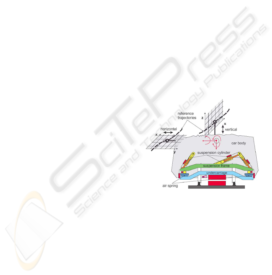
The active suspension system completely dis-
penses with shock absorbers in the secondary spring
system. Car body and chassis are connected only
by air springs. Damping is realized by an active
damping system with 10 hydraulic cylinders. These
actuators can also be used for tilting the shuttle in
the curves. Fig. 9 shows the main scheme of the
suspension module. The three ”vertical” cylinders are
mirrored on the rear of the vehicle. For the sake of
simplicity, the four longitudinal cylinders are omitted.
Figure 9: Reference trajectory for an active suspension sys-
tem
The classical control algorithm of an active suspen-
sion system uses acceleration measurements to deter-
mine the absolute velocity of the car body and dis-
placement measurements to determine the distance
between track and car body (relative position of the
car body). The relative position of the car body
and its first time derivative can be used to create
pseudo spring and damper forces by creating addi-
tional airspring displacements proportional to the de-
sired forces. The damper force created by this first
derivative is equivalent to damping forces generated
by passive dampers in so far as it is caused by relative
motion between the car body and the chassis. It thus
tries to suppress the relative motion and will hence-
STRUCTURED INFORMATION PROCESSING FOR SELF-OPTIMIZING MECHATRONIC SYSTEMS
235
forth be called ”relative damping”. The absolute car
body velocity - derived from acceleration measure-
ments by integration - forms a virtual damper attached
to a so-called ”sky hook”, which suppresses the abso-
lute movement of the car body. This damping will be
called ”absolute damping”.
As far as the damping of the resonance poles in the
car-body frequency response is concerned, both types
of damping are equivalent. However, time responses
of systems with identical damping of the car-body
eigenfrequency can differ significantly with different
shares of relative or absolute damping, respectively.
The reasons for this behavior are easy to understand
if one takes into account the extremes:
A system with a large portion of absolute damping
tries to prevent any movement of the car-body. As
any movement is perceived to be uncomfortable,
such a system is highly comfortable. However,
as the absolute damping suppresses the car-body
movement, a vehicle with large absolute damping is
not able to move up a slope or go around a curve -
after all, this requires vertical or lateral movement of
the car-body, respectively.
Systems with relative damping, on the other hand,
try to suppress the relative motion between car body
and chassis and thus between car body and track.
Taken to extremes, this means that the car body
follows the rail exactly, exciting the car body and
deteriorating the comfort. Therefore, systems with
relative dampers have poorer than those with absolute
damping. In return, they work in all situations.
One good way to overcome the difficulties of the
absolute damping is to introduce a reference trajec-
tory the car body is supposed to follow. The body
is thus not attached to the sky but to this trajectory
(Fig. 9 depicts this trajectory separately for the x/y-
and the x/z plane). This approach is in a way a
compromise between absolute and relative damping.
In a first approach the trajectory could be the ideal-
ized railway track. With increasing capability of ac-
tive displacement, however, the reference track can
change in order to compensate for unnecessary accel-
erations when entering a curve, etc. (M
¨
unch et al.,
2004) show how a multi-agent optimization can be
used to optimize the reference track using different
shuttles as probes.
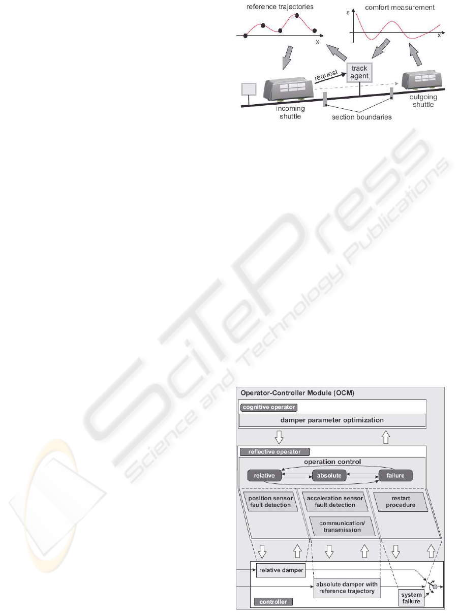
Fig. 10 shows the set-up of the optimization system
envisioned in (M
¨
unch et al., 2004). After dividing
the track into sections, an agent network is allocated
to the track. One track agent is allocated to each
section. It collects data about its respective section
and communicates with shuttles that run along. The
track agent transmits the actual reference trajectory
to a shuttle that wants to enter its section. After
completing the section the shuttle answers with a
performance rating, which is used by the track agent
Figure 10: Multi-agent optimization of the reference trajec-
tory
to optimize the trajectory.
The absolute damping with a self-optimizing track
reference presents a fine way to build the active
suspension control. However, there is a risk of
transmission failure of the reference trajectory, which
whould lead to a malfunction. The solution to this
problem is a reconfiguration of the system, changing
from the absolute damping to relative damping with
onboard sensors in case of a failed transmission of
the reference data. The presented software structure
in combination with the hybrid state charts is an
excellent means to implement the software in a
well-structured and clear way (see also (Burmester
et al., 2004)).
Figure 11: OCM of the active suspension system
ICINCO 2004 - SIGNAL PROCESSING, SYSTEMS MODELING AND CONTROL
236

Fig. 11 shows the operator-controller module
for the active suspension system. Three different
controllers can be selected: the controllers ”rela-
tive damper” and ”absolute damper with reference
trajectory” implement the concepts detailed above.
If underlying modules or the sensor-fault detectors
signal a system failure, the active suspension will be
shut off and the controller ”system failure” selected.
The controller choices are reflected in the reflective
operator. Each controller has a part in the reflective
operator dedicated especially to itself. The displace-
ment sensors as well as the acceleration sensors
each have their own fault detection systems, testing
plausibility and computing parity equations. The con-
troller ”absolute damper with reference trajectory”
requires additionally a communication/transmission
part that contacts the stationary agents and receives
the respective track reference trajectory from it. The
necessary procedure to start the suspension system
after a system failure is part of the reflective operator
dedicated to the controller ”system failure”.
Along with the reference trajectory, it is of course
also possible to optimize the controller parameters
themselves. This is done in the cognitive operator
”damper parameter optimization”. An example of the
implementation and the necessary software to recon-
figure the controllers for a hydraulic system can be
found in (Hestermeyer et al., 2004).
6 CONCLUSION
A consistent structuring of the controlling informa-
tion processing of mechatronic systems makes man-
ageable the whole range of complex systems up to
self-optimizing systems. Extension of classical de-
sign views, such as block diagrams, allows integration
of conventional design and analysis methods and per-
mits the designer to stick to his familiar views. The
next step will be the prototypical realization of a mod-
elling tool of reconfigurable systems according to the
concept presented. Already implemented OCM on
other platforms will subsequently be transferred into
it. This will allow us to verify and refine our concept.
REFERENCES
Burmester, S., Giese, H., and Oberschelp, O. (2004). Hy-
brid uml components for the design of complex self-
optimizing mechatronic systems. In 1st International
Conference on Informatics in Control, Automation
and Robotics (ICINCO), Setubal, Portugal.
Giese, H., Tichy, M., Burmester, S., Sch
¨
afer, W., and Flake,
S. (2003). Towards the compositional verification of
real-time uml designs. In European Software Engi-
neering Conference (ESEC), Helsinki, Finland. ACM
Press.
Harel, D. (1987). Statecharts: A visual formalism for com-
plex systems. Science of Computer Programming,
8(3):231–274.
Henzinger, T. A., Ho, P.-H., and Wong-Toi, H. (1995).
Hytech: The next generation. In 16th IEEE Real-Time
Symposium, Pisa, Italy. IEEE Computer Press.
Hestermeyer, T. (2003). railcab - an integrative system
for the 21st century. Urban Tranport International,
(50):24–25.
Hestermeyer, T., Becker, M., and Neuendorf, N.
(2001). Nichtlineare ABC-Regelungen mit Operator-
Controller-Struktur, abgestimmt auf F
¨
uhrung und
St
¨
orung der Straße. Essen. Haus der Technik.
Hestermeyer, T., M
¨
unch, E., and Sch
¨
afer, E. (2004). Model-
based online parameter optimization. In 3rd IFAC
Symposium on Mechatronic Systems, Sydney, Aus-
tralia. IFAC.
Hestermeyer, T. and Oberschelp, O. (2003). Selbst-
optimierende Fahrzeugregelung - Verhaltensbasierte
Adaption. In Gausemeier, J., L
¨
uckel, J., and Wal-
laschek, J., editors, Intelligente Mechatronische Sys-
teme, Paderborn. HNI-Verlag.
M
¨
unch, E., Hestermeyer, T., Oberschelp, O., Scheideler,
P., and Schmidt, A. (2004). Distributed optimization
of reference trajectories for active suspension with
multi-agent systems. In European Simulation Mul-
ticonference 2004 - Networked Simulations and Sim-
ulated Networks, pages 343–350, Magdeburg, Ger-
many. SCS.
Naumann, R. (2000). Modellierung und Verarbeitung ver-
netzter intelligenter mechatronischer Systeme. PhD
thesis, MLaP, University of Paderborn.
Naumann, R. and Rasche, R. (1998). Description and simu-
lation of hybrid mechatronic systems. In International
Workshop on Hybrid Systems: Computation and Con-
trol, Berkeley, CA.
Oberschelp, O., Hestermeyer, T., Kleinjohann, B., and
Kleinjohann, L. (2002). Design of self-optimizing
agent-based controllers. In CfP Workshop 2002 -
Agent-Based Simulation 3, Passau.
Storey, N. (1996). Safety-Critical Computer Systems.
Addison-Wesley, MA/Menlo Park, CA. Reading.
Tarr, P., Ossher, H., Harrison, W., and Sutton, S. M. (1999).
N degrees of separation: Multi-dimensional separa-
tion of concerns. In 1999 International Conference
on Software Engineering, pages 107–119, Los Ange-
les, CA.
UML (2003). UML 2.0 Superstructure Specification. Object
Management Group. Document ptc/03-08-02.
V
¨
ocking, H. (2003). Multirate-Verfahren und Umschalt-
strategien f
¨
ur verteilte Reglersysteme. Diplom-thesis,
MLaP, University of Paderborn.
STRUCTURED INFORMATION PROCESSING FOR SELF-OPTIMIZING MECHATRONIC SYSTEMS
237
