
PERFORMANCE OF ENHANCED-UMTS HSDPA USING
TRANSMIT DIVERSITY AND POWER CONTROL SCHEMES
João Carlos Silva, Nuno Souto, António Rodrigues
Instituto Superior Técnico/IT, Torre Norte 11-11, Av. Rovisco Pais 1, 1049-001 Lisboa, Portugal,
Américo Correia, Francisco Cercas
ADETTI/IT, Torre Norte 11-08, Av. Rovisco Pais 1, 1049-001 Lisboa, Portugal,
Nuno Cota
Instituto Superior de Engenharia de Lisboa,Rua Conselheiro Emídio Navarro-1, 1950-062 Portugal
Keywords: UMTS, HSDPA, Power Control, STD, STTD, Simulation Results
Abstract: This paper addresses the performance of the downlink High Speed Data Packet Access (HSDPA) in QPSK
mode. Transmit Diversity (TD) enhancement schemes such as Space Time Transmit Diversity (STTD) and
Selective Transmit Diversity (STD), alongside a Power Control (PC) scheme, are covered to improve the
system capacity. To evaluate the performance and the advantages of all the schemes under different
conditions, several combinations of these were simulated in the AWGN, Indoor A and Pedestrian A
channels. For the best combination, a gain of 11.5dB can be achieved, for a BLER of 1%.
1 INTRODUCTION
The 3G cellular system, known as UMTS, is in the
standard phase since 1999 and has the maximum
capacity of 2 Mbps. Although UMTS is being
licensed throughout Europe and implementation
involves huge investments, it is recognized that, at
the eve of implementation and deployment of the
system, still many aspects need to be investigated.
This is mainly related to the fact that there is no
previous experience on mobile cellular systems
operating in multi-service and multi-rate.
Furthermore, some applications require much
higher bit rates than those currently offered in
UMTS, like real-time audio/video on demand, web
browsing, etc.
This paper was elaborated as a result of the
participation in the B-BONE (Broadcasting and
Multicasting over Enhanced UMTS Mobile
Broadband Networks) project. The B-BONE project
aims to provide a fundamental contribution to the
evaluation and development of Enhanced UMTS
networks.
Future Enhanced-UMTS Systems are mostly
based on the current UMTS Systems but also add
new ‘Space Time Processing’ techniques, ‘namely
Adaptive Antennas, MIMO Systems, Space-Time
Coding and spectrally efficient coding/
modulation/ spreading schemes, to increase the
capacity of the access network up to 10 Mbps.
Recently, the HSDPA mode was introduced in
the standards, and the maximum downlink bit-rate
was increased significantly. Two possible
modulations were defined: QPSK and 16 QAM. The
latter mode delivers higher bit rate than the former
and is intended for good channel conditions. This
work addresses solely the usage of the QPSK
reference mode, though the main conclusions are
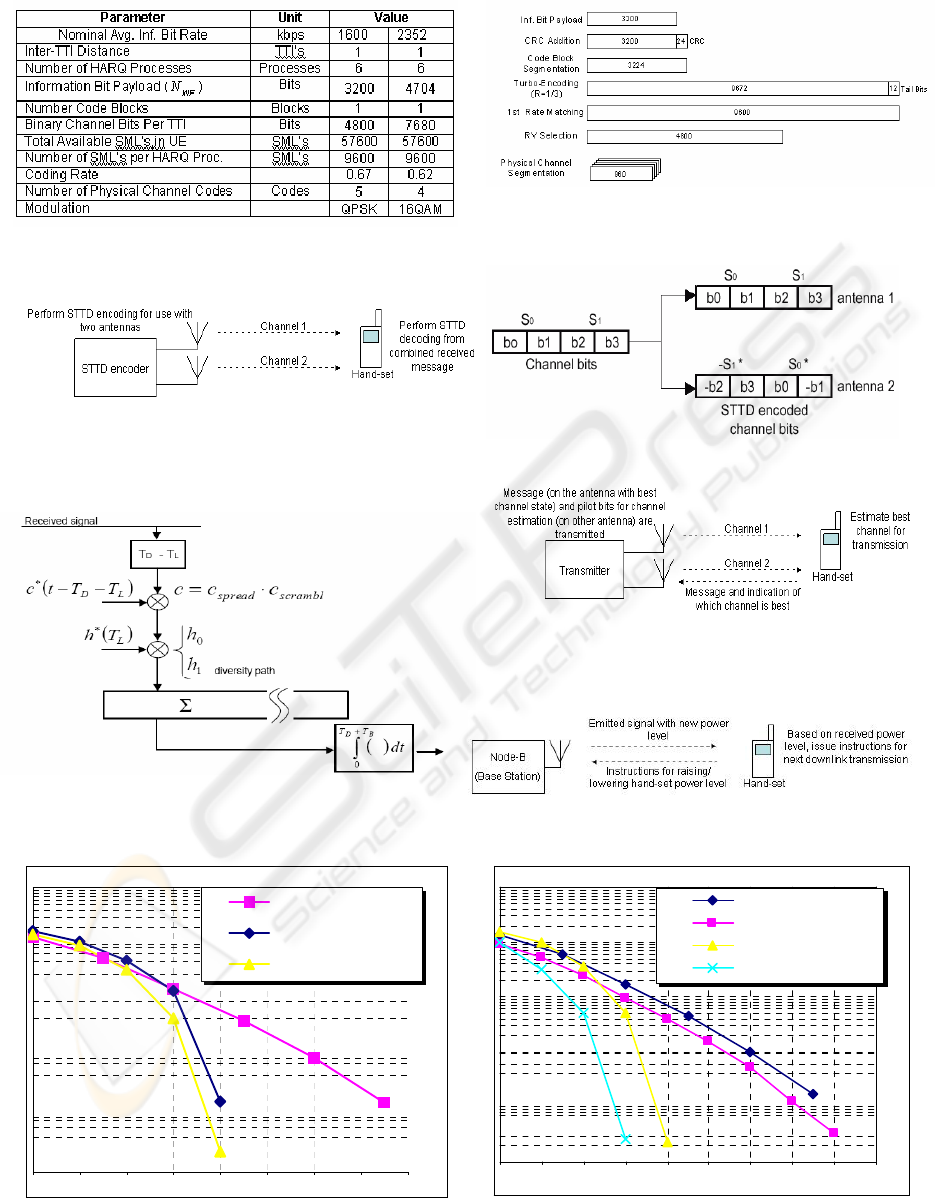
valid for both modes. The main parameters and
physical channel segmentation for the HSDPA-
QPSK mode are summarized in Figures 1 and 2,
respectively. Note that the turbo code has a rate of
46
Carlos Silva J., Souto N., Rodrigues A., Correia A., Cercas F. and Cota N. (2004).
PERFORMANCE OF ENHANCED-UMTS HSDPA USING TRANSMIT DIVERSITY AND POWER CONTROL SCHEMES.
In Proceedings of the First International Conference on E-Business and Telecommunication Networks, pages 46-51
DOI: 10.5220/0001383400460051
Copyright
c
SciTePress

1/3, and 50% puncturing is applied to its output.
Five physical channels are used, which are spreaded
with a Spreading Factor (SF) of 16. Sub-frames of 2
ms are used, corresponding to 3 time slots of the
normal UMTS mode. A link level simulator was
built, from the transport block level, turbo coding,
transmission of the encoded chips, emulation of the
channel, RAKE receiver, turbo decoding, and all
necessary operations up to the received transport
block. All modules specified in the standards were
built (3GPP, 25.211-213), with the addition of the
STD, STTD (3GPP 25.211) and PC (3GPP 25.101)
modules. Although HSDPA is based on Adaptive
Coding and Modulation (AMC), PC was considered
in order to further improve the performance of the
system, although the AMC itself is not considered.
Results were drawn with and without the
enhancement schemes, in order to evaluate the
performance gains.
This paper is structured as follows: in section 2,
the STD, STTD and PC are summarized, and section
3 analyzes the obtained results. Conclusions are
drawn in section 4.
2 ENHANCEMENT SCHEMES
Both STD and STTD schemes are based on the
usage of 2 antennas, though more antennas could be
employed. The STTD scheme consists on having the
message bits transmitted by two antennas (Figure 3),
encoded as shown in Figure 4. The hand-set receives
both transmissions from the antennas, and performs
the STTD decoding, as explained in Figure 6 and
Equations (1) and (2). From Figure 6, the signal after
the RAKE receiver is:
()
()
()
***
1001100
22 2
**'
001100
***
2001101
222
** '
0011 10
***
1100110
22 2
**'
100101
21
()
()
(2 )
(2 )
rk T S c h S c h n c h
Sc h Schh n
rk T S c h S c h n c h
Schh Sc h n
rk T S c h S c h n c h
Sc h S c hh n
rk T S c
=⋅⋅−⋅⋅+×⋅=
=⋅ ⋅ −⋅⋅⋅+
=⋅⋅−⋅⋅+×⋅=
=⋅ ⋅⋅−⋅ ⋅ +
=⋅⋅+⋅⋅+×⋅=
=⋅ ⋅ +⋅ ⋅⋅+
=⋅⋅
()
***
00 11 1
222
** '
1010 11
hSchn ch
Sc hh S c h n
+⋅⋅+ ×⋅=
=⋅ ⋅⋅+ ⋅ ⋅ +
(1)
The final STTD-decoding combination yields:
()
()
~
222
*''
0
12 0 01
~
222
*''
1
12101
() (2)
(2 ) ( )
SrkTrkT Sc h h n
SrkTrkT Sc h h n
=+ =⋅⋅++
=−=⋅⋅++
(2)
The STD algorithm is quite simple; the mobile
chooses the best antenna for transmission, and uses
such antenna until the other antenna starts yielding
better estimated values for the channel state. The
equivalent received power for the STD scheme is
thus
(
)
22
01
max ,
STD
Phh=
instead of
(
)
22
01
2
STTD
hh
P
+
=
. Note that, in the STTD
scheme, both antennas transmit the original
message, though the second antenna uses a modified
version of the message. There is no feedback for
these kind of transmit diversity. In the STD scheme,
only one antenna transmits the message, whereas the
other antenna transmits pilot bits to assess the
channel quality, with the mobile transmitting back
control bits in order to choose the best antenna
(closed loop scheme – Figure 5). The antenna that
transmits the message may vary, according to the
channel state associated to each antenna.
At the receiver side, a soft decision Rake receiver
was built, and a turbo decoder using the Maximum
A Posteriori (MAP) algorithm (Bahl, 1974), was
employed. A maximum of 8 iterations were used,
with iteration stop criteria linked to the Cyclic
Redundancy Check (CRC) result. The simulated PC
mechanism was the standardized downlink type 1,
with a step size of 1dB (which is the value
mandatory for the UTRAN to support, though other
values can also be used) and a delay of 1 Time Slot
(TS), due to being the PC scheme that yields best
results (Silva, 2003). A dynamic range of ±15dB
was employed, to simulate saturation. Figure 7
shows a simple diagram illustrating the downlink
Power Control scheme. At a time resolution equal to
1 TS (0,667ms), the power control algorithm
instructs the hand-set to increase/ decrease its power
level by 1dB. There is a delay of 1TS for the
simulated case, since the corrected power level for
the current TS takes into account the power level of
the previous TS.
The Tapped Delay Line (TDL) model specified
for UMTS (ETSI, 1998), (3GPP 25.943) was
simulated, and a speed of 3 km/h was used for the
Indoor A channel, whereas a velocity of 10 km/h
was used for the Pedestrian A channel. Only fast
fading was considered; slow fading/ shadowing was
assumed to be completely compensated. Perfect
channel estimation was assumed. For the STD
simulations, a delay equivalent to 1 TS was used, in
order to model a realistic scenario. When the STD
was combined with PC, a smart mechanism was
activated which reduced the STD delay to 0, thus
simulating a STD capable of predicting what the
power control is about to do for the next TS, and to
anticipate what the next channel value will be.
Though the latter assumption is not very realistic,
PERFORMANCE OF ENHANCED-UMTS HSDPA USING TRANSMIT DIVERSITY AND POWER CONTROL
SCHEMES
47

the practical deviation of results that arises from it is
negligible for channels with low speed values, such
as those simulated.
3 NUMERICAL RESULTS
Bit Error Rates (BER) and Block Error Rates
(BLER) were obtained via Monte Carlo simulation
of the different scenarios with the link level
simulator using a total number of iterations
sufficient enough to ensure convergence.
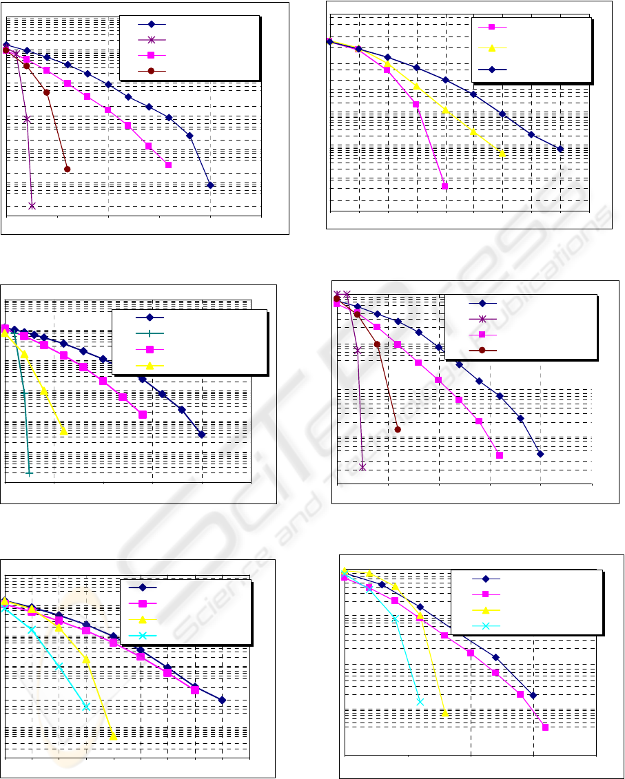
The simulated results are depicted in Figures 8-
19. After analyzing the results, the performance gain
by applying transmit diversity can be quantified. We
note that STD has always a better performance than
STTD, as would be expected, due to always
choosing the best antenna for transmission.
Results were obtained for using PC Type 1 with
1 TS resolution simulated alone and also in
combination with STTD and STD. From the results,
it can be seen that the usage of PC combined with
either STD or STTD is clearly the solution with
greatest performance increase over the normal
QPSK simulations.
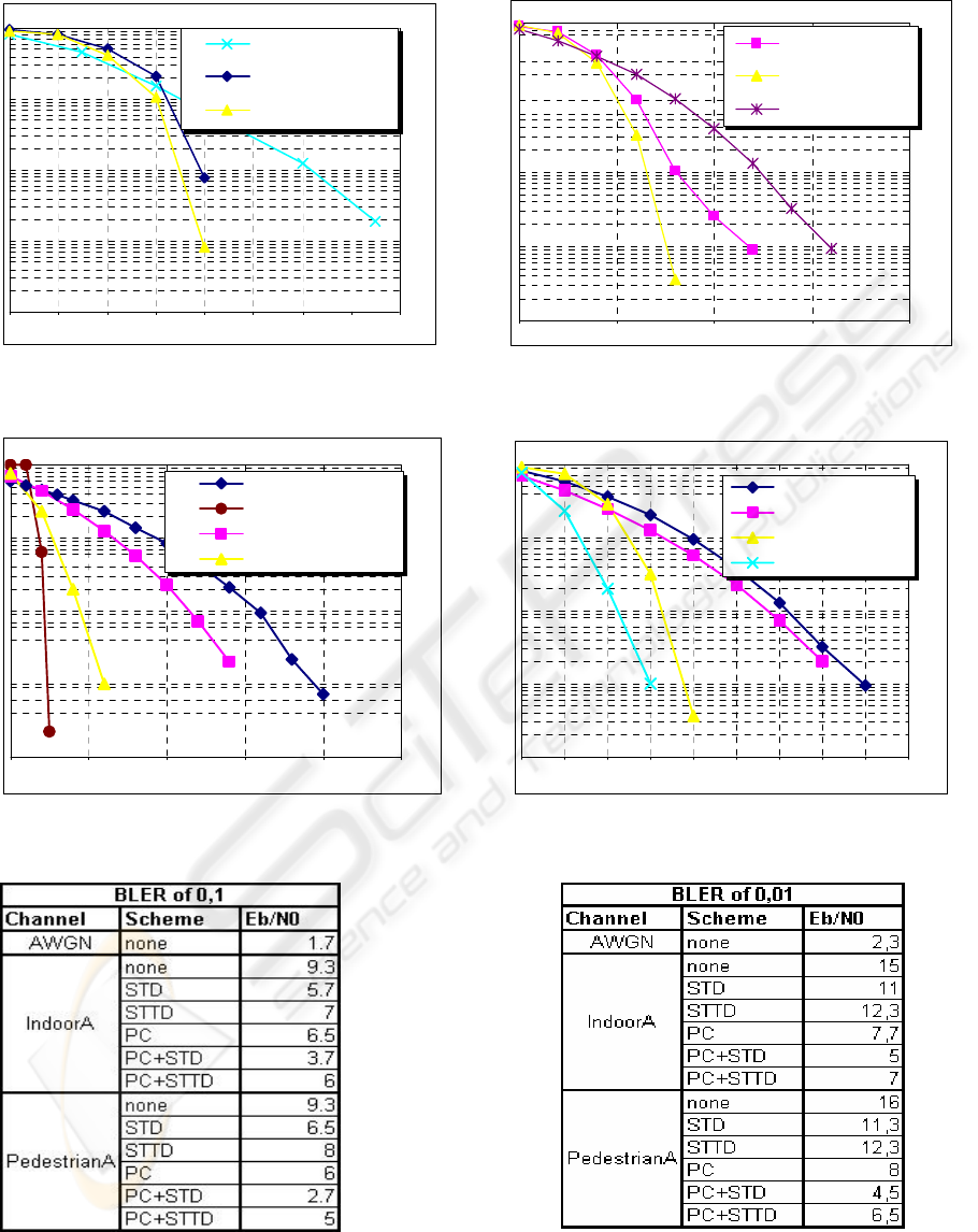
It can also be seen that both Indoor A and
Pedestrian A channels are similar in performance,
though the Indoor A channel is slightly better
without power control, and the Pedestrian A channel
is better with schemes involving PC. This result is
simply explained by the fact that PC schemes
usually work better in channels that are close to a
single Rayleigh path, such as the Pedestrian A
channel. This is due to the minimization of
intersymbolic interference, effectively aiding the PC
algorithm, since all the power adjustments are
practically for the main path of the message.
Figures 20 and 21 show the Eb/N0 values for the
different schemes, operating under considered
normal operation points (BLER of 0.1 for non-real
time applications and of 0.01 for real-time
applications).
4 CONCLUSIONS
By direct inspection of the results, it was shown that
the HSDPA mode alone, without the enhancement
schemes such as transmit diversity and power
control, performs very poorly. Thus, in order to
achieve high bit rates, and use the UMTS to its full
potential, enhancement schemes, such as STD,
STTD and PC need to be employed, in conjunction
with each other.
In order to further close the gap to the AWGN
results, more complex schemes can be employed.
This can be done by using Adaptive Antennas,
MIMO Systems, higher order Space-Time Coding
techniques (the work in this paper considered an
order 2 system, using 2 antennas for the STD and
STTD scheme), Power Control with less delay and
spectrally efficient coding/ modulation/ spreading
schemes, namely the use of Code-Spread (CS)
CDMA schemes (Souto, 2004). The usage of AMC
effectively combined with the proposed schemes
could also further improve the system’s
performance.
REFERENCES
3GPP, 25.212-370, ‘Multiplexing and Channel Coding
(FDD)’.
3GPP, 25.213-360, ‘Spreading and Modulation (FDD)’.
L.R. Bahl, J. Cocke, F. Jelinek and J. Raviv, “Optimal
decoding of linear codes for minimizing symbol error
rate” IEEE Trans. Inform. Theory, vol. IT-20, pp.284-
287, Mar. 1974.
3GPP, 25.211-370, ‘Physical Channels and mapping of
Transport Channels onto Physical Channels’.
3GPP TS 25.101 V5.4.0, ‘Power Control’
J.C. Silva, N. Souto, A. Correia, F. Cercas, A. Rodrigues,
“Characterization of Power Control for UMTS”,
WPMC 2003, Yokosuka, Japan
ETSI, Selection procedures for the choice of radio
transmission technologies of UMTS, TR 101 112
v3.2.0, ETSI, Sophia Antipolis, France, 1998
3GPP, Deployment aspects, 3GPP TR 25.943 v5.1.0,
Sophia Antipolis, France, 2002.
N. Souto, J.C. Silva, F. Cercas ‘Usage of Turbo Super-
Orthogonal Codes for an enhanced UMTS CS-CDMA
Uplink transmission’, to be presented in VTC’04
Spring, Milano, Italy, 2004.
ICETE 2004 - WIRELESS COMMUNICATION SYSTEMS AND NETWORKS
48
BER vs Eb/N0 - Indoor A
1,E-05
1,E-04
1,E-03
1,E-02
1,E-01
1,E+00
0 2 4 6 8 10 12 14 16
Eb/N0 (dB)
BER
QPSK-STTD
QPSK PC
QPSK STTD+PC
BER vs Eb/N0 - Indoor A
1,E-05
1,E-04
1,E-03
1,E-02
1,E-01
1,E+00
024681012141618
Eb/ N0 ( dB)
BER
QPSK-STTD
QPSK STD
QPSK STTD+PC
QPSK STD+PC
Figure 1: HSDPA main parameters Figure 2: Physical channel segmentation for HSDPA
Figure 3: Schematics of STTD operation Figure 4: Schematics of STTD encoder
Figure 5 – Schematics of STD algorithm
Figure 6: STTD reception scheme Figure 7: Schematics of downlink Power Control algorithm
Figure 8: HSDPA BER results for Indoor A Figure 9: HSDPA BER results for Indoor A
(PC, STTD and PC+STTD) (Comparison of STD and STTD, with and without PC)
PERFORMANCE OF ENHANCED-UMTS HSDPA USING TRANSMIT DIVERSITY AND POWER CONTROL
SCHEMES
49
BER vs Eb/N0 - Indoor A
1, E - 0 6
1, E - 0 5
1, E - 0 4
1, E - 0 3
1, E - 0 2
1, E - 0 1
1, E + 0 0
0 5 10 15 2 0 2 5
Eb/ N0 (dB)
BER
QPSK
QPSK AWGN
QPSK STD
QPSK STD+PC
BER vs Eb/N0 - Pedestrian A
1,E-06
1,E-05
1,E-04
1,E-03
1,E-02
1,E-01
1,E+00
024681012141618
Eb/ N0 ( dB)
BER
QPSK PC+STTD
QPSK PC
QPSK STTD
BLER vs Eb/N0 - Indoor A
1, E - 0 4
1, E - 0 3
1, E - 0 2
1, E - 0 1
1, E + 0 0
0 5 10 15 2 0 2 5
Eb/ N0 (dB)
BLER
QPSK
QPSK AWGN
QPSK STD
QPSK STD+PC
BLER vs Eb/N0 - Indoor A
1, E - 0 4
1, E - 0 3
1, E - 0 2
1, E - 0 1
1, E + 0 0
0 5 10 15 2 0
Eb/ N0 (dB)
BLER
QPSK-STTD
QPSK STD
QPSK STTD+PC
QPSK STD+PC
Figure 10: HSDPA BER results for Indoor A Figure 11: HSDPA BER results for PedestrianA
(Normal, STD, PC+STD and AWGN) (PC, STTD and PC+STTD)
BER vs Eb/N0 - Pedestrian A
1,E-06
1,E-05
1,E-04
1,E-03
1,E-02
1,E-01
1,E+00
0 5 10 15 20 25
Eb/N0 (dB)
BER
QPSK
QPSK AWGN
QPSK STD
QPSK STD+PC
Figure 12: HSDPA BER results for PedestrianA Figure 13: HSDPA BLER results for IndoorA
(Normal, STD, PC+STD and AWGN) (Normal, STD, PC+STD and AWGN)
BER vs Eb/N0 - Pedestrian A
1,E-06
1,E-05
1,E-04
1,E-03
1,E-02
1,E-01
1,E+00
0 2 4 6 8 10 12 14 16 18
Eb/N0 (dB)
BER
QPSK STTD
QPSK STD
QPSK PC+STTD
QPSK STD+PC
Figure 14: HSDPA BER results for PedestrianA Figure 15: HSDPA BLER results for IndoorA
(Comparison of STD and STTD, with and without PC) (Comparison of STD and STTD, with and without PC)
ICETE 2004 - WIRELESS COMMUNICATION SYSTEMS AND NETWORKS
50
BLER vs Eb/N0 - Pedestrian A
1, E - 0 4
1, E - 0 3
1, E - 0 2
1, E - 0 1
1, E + 0 0
0 5 10 15 2 0
Eb/ N0 (dB)
BLER
QPSK-PC
QPSK-PC+STTD
QPSK-STTD
BLER vs Eb/N0 - Indoor A
1, E-04
1, E-03
1, E-02
1, E-01
1, E+00
02 46810121416
Eb/ N0 ( dB)
BLE R
QPSK-STTD
QPSK PC
QPSK STTD+PC
Figure 16: HSDPA BLER results for IndoorA Figure 17: HSDPA BLER results for PedestrianA
(PC, STTD and PC+STTD) (PC, STTD and PC+STTD)
BLER vs Eb/N0 - Pedestrian A
1,E-04
1,E-03
1,E-02
1,E-01
1,E+00
0 5 10 15 20 25
Eb/N0 (dB)
BLER
QPSK
QPSK AWGN
QPSK STD
QPSK-PC+STD
BLER vs Eb/N0 - Pedestrian A
1,E-04
1,E-03
1,E-02
1,E-01
1,E+00
0 2 4 6 8 1012141618
Eb/N0 (dB)
BLER
QPSK-STTD
QPSK STD
QPSK-PC+STTD
QPSK-PC+STD
Figure 18: HSDPA BLER results for PedestrianA Figure 19: HSDPA BLER results for PedestrianA
(Normal, STD, PC+STD and AWGN) (STD and STTD, with and without PC)
Figure 20: Results for BLER of 0,1 Figure 21: Results for BLER of 0,01
PERFORMANCE OF ENHANCED-UMTS HSDPA USING TRANSMIT DIVERSITY AND POWER CONTROL
SCHEMES
51
