
INTEGRATING REQUIREMENTS & SPECIFICATIONS IN THE
TELECOMMUNICATIONS SERVICE CREATION PROCESS
Dionisis Adamopoulos
Department of Technology Education & Digital Systems, University of Piraeus, Greece
Keywords: New telecommunications services, service analysis, service creation, multiservice networks
Abstract: Existing telecommunications systems are gradually converging into a ubiquitous information infrastructure
inside an open deregulated multi-provider telecommunications market place. Additionally, the demand for
new value-generating telecommunications services is increasing and will increase rapidly in the years to
come. Therefore, in order to derive a viable service paradigm, a service creation methodology is essential.
After a brief presentation of such a proposed methodology, this paper focuses on its service analysis phase.
More specifically, it determines the activities that take part in the service analysis phase and the artifacts
that are produced, and examines important matters related to the role of use cases and the definition of
conceptual models, interaction diagrams, operation contracts and state diagrams in the framework of tele-
communications service engineering, exploiting the use of UML. Finally, alternative and complementary
approaches for service analysis are highlighted and a validation attempt is briefly outlined.
1 INTRODUCTION
The telecommunications world is currently ex-
periencing dramatic changes due to the rapid tech-
nological development, the changes in the regulatory
environment and the increased competition. A direct
result is the significant increase in the number, vari-
ety and sophistication of telecommunications ser-
vices that telecommunications companies offer in an
attempt to satisfy the high and continuously ex-
panding customer demand for powerful communi-
cation and information capabilities. The timely
availability of these new value-generating telecom-
munications services corresponding to the needs of
the market is an important condition for gaining a
competitive advantage and for the exploitation of the
huge telecommunication potential that will be of-
fered by the broadband network infrastructure that is
currently under development.
Under these conditions, a service development
methodology has a central role, as it ensures the suc-
cessful guidance of service developers during the
entire service creation process. Therefore, such a
methodology is proposed in this paper, compatible
with and influenced by the state of the art service
creation technologies of Open Service Access
(OSA), Parlay and Java APIs for Integrated Net-
works (JAIN) (Jormakka, 2002), and conformant to
the open service architectural framework specified
by the Telecommunications Information Networking
Architecture Consortium (TINA-C) (TINA-C, 1997)
(Berndt, 2002). The paper emphasises the service
analysis phase of the proposed methodology that
determines the usefulness of service engineering
activities and is capable of fulfilling the emerging
increased expectations regarding their value and
impact.
2 THE PROPOSED SERVICE
CREATION METHODOLOGY
Because of the recent diversification of the tele-
communications environment, it is necessary to de-
fine and develop a telecommunications service in-
frastructure (an information network), above the
bearer network infrastructure, which will control and
manage the distribution of information in its various
media manifestations, between geographically dis-
tributed user entities satisfying their needs in the
best possible way. To achieve such an ambitious, yet
strategic to the telecommunications operator’s goal,
a service creation methodology based on the rich
conceptual model of TINA-C is proposed (Ada-
mopoulos, 2002).
A high-level or macro-level view of the pro-
posed service creation methodology can be seen in
136
Adamopoulos D. (2004).
INTEGRATING REQUIREMENTS & SPECIFICATIONS IN THE TELECOMMUNICATIONS SERVICE CREATION PROCESS.
In Proceedings of the First International Conference on E-Business and Telecommunication Networks, pages 136-143
DOI: 10.5220/0001393701360143
Copyright
c
SciTePress
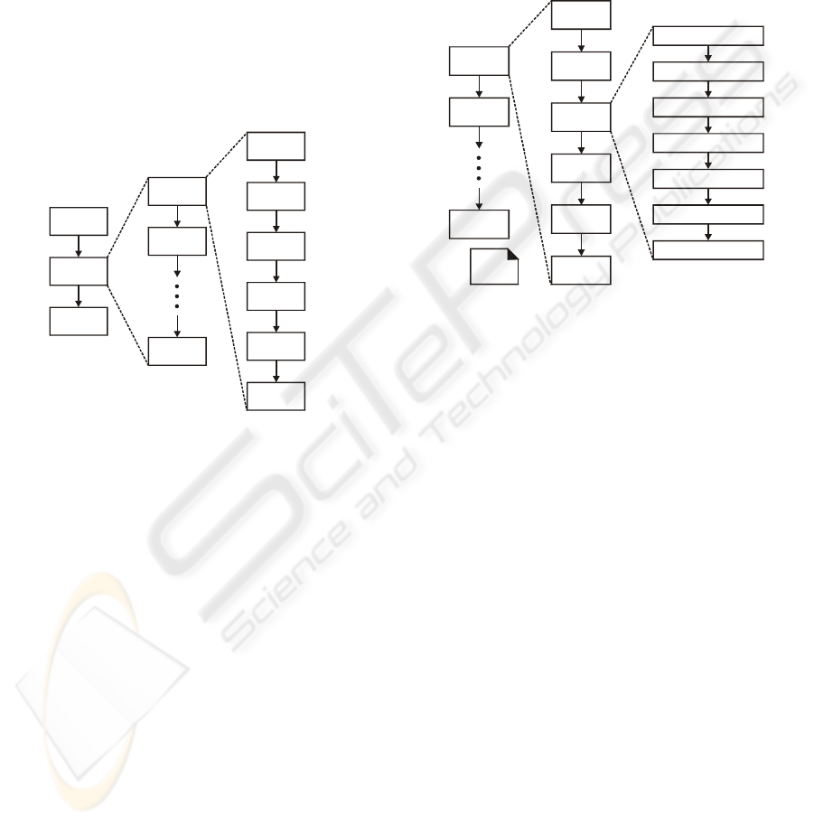
Figure 1. The proposed service development process
is based on an iterative and incremental, use case
driven approach. An iterative service creation life
cycle is adopted, which is based on successive
enlargement and refinement of a telematic service
through multiple service development cycles within
each one the telematic service grows as it is enriched
with new functions. More specifically, after the re-
quirements capture and analysis phase, service de-
velopment proceeds in a service formation phase,
through a series of service development cycles. Each
cycle tackles a relatively small set of service re-
quirements, proceeding through service analysis,
service design, service implementation and valida-
tion, and service testing. The telematic service grows
incrementally as each cycle is completed.
Figure 1: Overview of the proposed service
creation methodology
According to Figure 1 the main phases of the
proposed methodology are the following:
• Requirements capture and analysis phase: It iden-
tifies the telematic service requirements (together
with a number of roles), and presents them in a
structured way.
• Service analysis phase: It describes the semantics
of the problem domain that the telematic service is
designed for. Thus, it identifies the objects that
compose a service (information service objects),
their types, and their relationships.
• Service design phase: It produces the design speci-
fications of the telematic service under examina-
tion. Computational modelling is taking place in
this phase and thus the service is described in
terms of computational objects interacting with
each other.
• Service implementation phase: In this phase the
pieces of the service software (computational
objects) are defined and implemented in an object-
oriented programming language (e.g. C++, Java),
inside a Distributed Processing Environment
(DPE).
• Service validation and testing phase: It subjects
the implemented telematic service to a variety of
tests in order to ensure its correct and reliable op-
eration.
• Service optimisation phase: It examines thor-
oughly the service code in order to improve its
performance in the target DPE, and thus prepare
the telematic service for a successful deployment.
Figure 2: Service analysis phase activities
As can be seen from Figure 1, the proposed
methodology is conceptually consistent with the
viewpoint separation as advocated by TINA-C in
accordance with the Reference Model for Open Dis-
tributed Processing (RM-ODP). It has to be stressed
that the proposed methodology does not imply a
waterfall model in which each activity is done once
for the entire set of service requirements. Further-
more, graphical and textual notations are proposed
for almost all phases to improve the readability of
the related results and ensure a level of formalism
sufficient to prevent any ambiguity (Adamopoulos,
2002). In the following paragraphs the service
analysis phase of the proposed methodology is ex-
amined focusing on its essential characteristics and
artifacts.
3 THE SERVICE ANALYSIS
PHASE
The aim of this phase is to determine the functional-
ity needed for satisfying the service requirements
that were identified in the requirements capture and
analysis phase and to define the software architec-
ture of the service implementation. For this reason,
the focal point shifts from the service boundary to
the internal service structure (Adamopoulos, 2002).
Requirements
Capture and
Analysis
Service
Development
Cycle 1
Requirements
Refinement
Service
Formation
Service
Optimisation
Service
Development
Cycle 2
Service
Development
Cycle n
A
rtifacts
Synchronisation
Service Analysis
Service Design
Service
Implementation
Service Validation
and Testing
Service
Development
Cycle 1
Requirements
Refinement
Service
Development
Cycle 2
Service
Development
Cycle n
Artifacts
Synchronisation
Service Analysis
Service Design
Service
Implementation
Service Validation
and Testing
Refine Glossary
2
Define Essential Use Cases
1
Refine the Use Case Diagram(s)
Define Service Conceptual Models
Define Service
Sequence Diagrams
Define Service
Operation Contracts
Define Service State Diagrams
3
1: if not yet
done
2: ongoing
3: optional
Notes
INTEGRATING REQUIREMENTS & SPECIFICATIONS IN THE TELECOMMUNICATIONS SERVICE CREATION
PROCESS
137
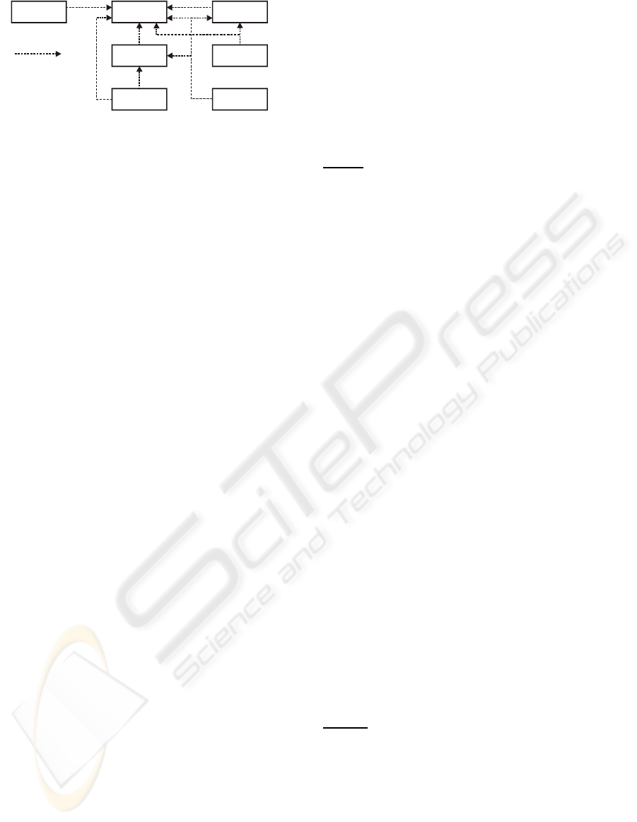
Figure 3: Service analysis phase artifact dependencies
The activities that take place in this phase can be
seen in Figure 2. The linear order that may be in-
ferred from this figure is not strictly the case, as
some artifacts may be created in parallel (e.g. the
service conceptual model and the glossary). The
dependencies between the artifacts produced can be
seen in Figure 3. The most important activities of
this phase are examined in the following sections.
3.1 Definition of Service Conceptual
Models
The service analysis phase is the first phase of the
service creation process where the telematic service
is decomposed into its constituent parts (service in-
formation objects or service concepts), with the ap-
propriate relationships among them, in an attempt to
gain an overall understanding of the service. The
resulting (main) service conceptual model, which is
the most important artifact that is created during the
service analysis phase, represents a restatement, in a
graphical notation, of the problem statement, as it
was expressed in the previous phase.
It involves identifying a rich set of service con-
cepts regarding the telematic service under exami-
nation by investigating the service domain and by
analysing the essential use cases. Therefore, it de-
scribes what the service is in terms of interesting and
meaningful (to the service developer) entities / con-
cepts that constitute it and couplings / associations
between them (Declan, 1997). These couplings de-
fine relationships between two service Information
Object (IO) classes. In UML, a service conceptual
model can be illustrated with a set of static structure
diagrams in which no operations are defined. It has
to be stressed that a service conceptual model is a
representation of real-world concepts or actual
things, and not a representation of software compo-
nents (software entities). However, there is no such
thing as a single correct service conceptual model.
All service conceptual models are approximations of
the service domain under examination.
The main service conceptual model is accompa-
nied by a set of ancillary service conceptual models.
These models are derived by (and correspond to) a
number of generic information models deduced from
the TINA-C service architecture (TINA-C, 1997)
and complement semantically the main service con-
ceptual model with useful session related concepts
and structures. More specifically, the ancillary mod-
els refer to the modelling of session roles, (TINA-C)
sessions, access and service sessions, and to the
classification of access and service sessions (Choi,
2003).
The following steps specify the main service
conceptual model:
Step 1:
Identify the service concepts.
A central task when creating a service concep-
tual model is the identification of the service con-
cepts. It has to be noted as a general guideline that it
is better to overspecify a service conceptual model
with many fine-grained concepts than to under-
specify it. However, it is possible that some service
concepts will be missed during the initial attempt to
identify service concepts. These concepts will be
discovered later during the consideration of associa-
tions or attributes, or during the service design
phase. When found, the initially missed service con-
cepts, should be added to the service conceptual
model.
Two techniques are proposed for the identifica-
tion of service concepts. The first is based on the use
of a service concept category list, which contains
categories that are usually worth considering, though
not in any particular order of importance. Another
useful technique is to consider the noun phrases in
the text of the expanded use cases as candidate ser-
vice concepts or attributes. However, this noun
phrase identification technique must be carefully
applied, as a mechanical noun-to-concept mapping
isn’t possible, and words in natural languages are
ambiguous. Nevertheless, this technique is recom-
mended to be used in combination with the service
concept category list technique.
Taking into account the previous discussion, the
following actions take place when identifying the
service concepts during this step:
• Apply the service concept category list technique.
• Apply the noun phrase identification technique.
• Draw an initial service conceptual model by
representing graphically only the service concepts.
• Identify useful type hierarchies (optionally).
Step 2:
Identify associations between the service
concepts.
After identifying the service concepts, it is also
necessary to identify those associations of the ser-
vice concepts that are needed to satisfy the informa-
tion requirements of the current use case(s) under
development and which aid the comprehension of
the service conceptual model. The associations that
should be considered in order to be included in a
service conceptual model are the associations for
which the service requirements suggest or imply that
knowledge of the relationship that they present
Service
Sequence
Diagrams
dependency on
Use Case
Diagram(s)
Use Cases
(expanded,
essential)
Service
Operation
Contracts
Service
Conceptual
Model
Glossary
Service State
Diagrams
ICETE 2004 - GLOBAL COMMUNICATION INFORMATION SYSTEMS AND SERVICES
138
needs to be preserved for some duration (“need-to-
know” associations) or are otherwise strongly sug-
gested in the service developer’s perception of the
problem domain. Furthermore, it is usually worth
considering, a common associations list which con-
tains some common categories of associations.
It has to be noted that it is generally undesirable
to overwhelm the service conceptual model with
associations that are derivable, not strongly required
and which do not increase understanding. Too many
associations tend to confuse a service conceptual
model rather than clarify it. Their discovery can be
time-consuming and with marginal benefit. How-
ever, associations should also ensure that the service
conceptual model offers an essential understanding
of the important service concepts.
Taking into account the previous discussion, the
following actions take place when identifying
associations between the service concepts during
this step:
• Find the need-to-know associations.
• Consider the common associations list.
• Consider aggregation (composite or shared),
derived, qualified, and recursive or reflexive
associations, based on their value in improving
understanding of the service domain (optional
action).
• Select the desirable associations that will be
included in the main service conceptual model.
Step 3:
Identify attributes of the service concepts.
A service conceptual model should include all
the attributes of the identified service concepts for
which the service requirements suggest or imply a
need to remember information. These attributes
should preferably be simple attributes or pure data
values. Caution is needed to avoid modelling a
(complex) service concept as an attribute or relating
two service concepts with an attribute instead of an
association.
Step 4:
Draw the main service conceptual model.
Adding the identified type hierarchies, associa-
tions and attributes to the initial service conceptual
model, forms the main service conceptual model. It
has to be noted that a verb phrase should be used for
naming an association, in such a way that the asso-
ciation’s name together with the names of the ser-
vice concepts that it relates create a sequence that is
readable and meaningful.
The proposed methodology considers the TINA-
C service architecture (which has a direct and sig-
nificant influence to subsequent service creation
technologies) in a critical manner with the intention
to extract from it useful concepts and guidelines /
techniques. Taking into account this attitude, a num-
ber of generic TINA-C information models were
formed, by considering parts of the documentation
that is available by TINA-C (TINA-C, 1997). The
customisation of these information models according
to the service requirements results in the ancillary
service conceptual models, which in combination
with the main service conceptual model, describe the
semantics of the service domain under examination
in a clear, concise, and unambiguous way (Choi,
2003).
The generic TINA-C information models that are
the basis of the ancillary service conceptual models
are briefly described in the following paragraphs. It
is stressed that these information models have a pure
conceptual / analytical role and they are considered
by the proposed methodology released from most of
the details that the TINA-C service architecture as-
sociates with them (e.g. feature sets ).
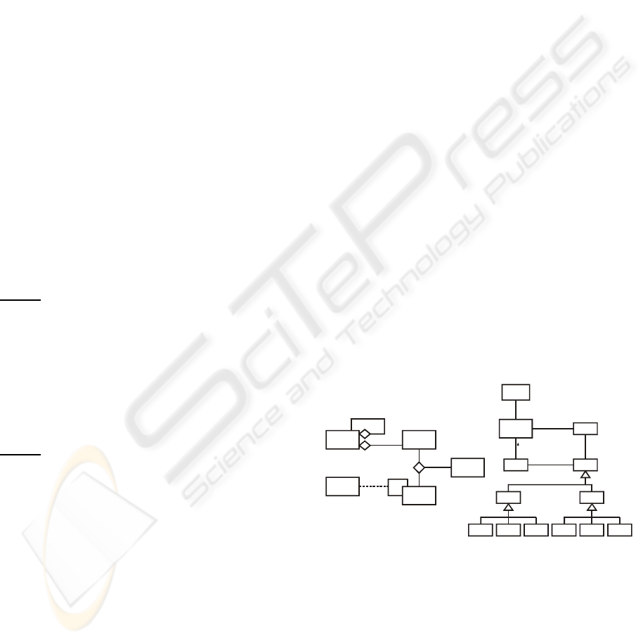
The session related information models
The session information model is depicted in
Figure 4(a) and is valid for all session related
telematic services. As a session related service may
extend over multiple business administrative do-
mains, it is intuitive and useful to model the service
as an aggregation of one or more domain services,
where each domain service represents a part of a
service confined to a single domain. Just as a session
represents an instance of a service, a domain session
represents an instance of a domain service. Domain
sessions may interact to establish services extending
over multiple domains.
As can be seen in the session role information
model, which is depicted in Figure 4(b), business
administrative domains are able to take different
session roles during the access and usage interac-
tions that occur between them.
Figure 4: Important session related information models:
(a) The session information model,
(b) The session role information model.
The access session related information models
Taking into account the generic TINA-C session
related information models of Figure 4 and the dif-
ferent types of sessions that can be established be-
tween business administrative domains, access ses-
Business
Admi nistra tive
Domain
Sessi on-
related
service
*
*
*
1..*
Domain
Service
Domain
Sessi on
Binding
Domain
Session
Business
Administrative
Domain
Stakeholder
Runs
1..*
*
*
1..*
Acts-on-behalf-of
Performs
Performs
Business
Role
Sessi on
Role
Access
Role
Usage
Role
Access
User
Access
Provider
Access
Peer
Usage
Party
Usage
Provider
Usage
Peer
Principal
(a) (b)
INTEGRATING REQUIREMENTS & SPECIFICATIONS IN THE TELECOMMUNICATIONS SERVICE CREATION
PROCESS
139
sions can be classified according to the specialisa-
tion hierarchy shown in Figure 5(a).
The access session related service IOs and their
relationships are depicted in the information model
of Figure 5(b). In this figure, the Domain Access
Session (D_AS) service IO is associated with a par-
ticular domain and represents the generic informa-
tion required to establish and support access interac-
tions between two domains. Furthermore, it is spe-
cialised into UD_AS (managed by the user), PD_AS
(managed by the provider) and PeerD_AS service
IOs, as each D_AS is associated with a particular
access role. All information that is used directly by
the D_AS for authorisation decisions, constraints
and customisation of the D_ASs, Access Sessions
and Service Sessions is contained in the User Pro-
file.
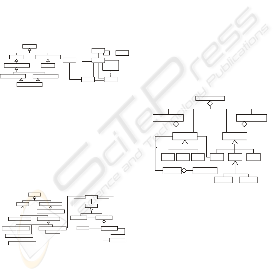
Figure 5: Important access session related information
models:
(a) Classification of the access session,
(b) The access session information model.
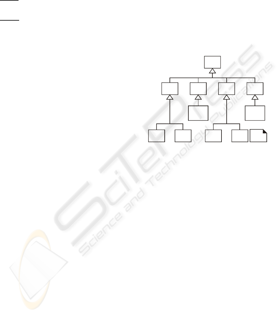
The service session related information models
Service sessions can be classified according to
the specialisation hierarchy shown in Figure 6(a).
The service session related service IOs and their
relationships are depicted in the information model
of Figure 6(b). Every service session consists of us-
age and provider service sessions. Each member of a
session, i.e. an end-user, a resource or another ses-
sion, is associated with a usage service session.
Figure 6: Important service session related information
models:
(a) Classification of the service session,
(b) The service session information model.
Furthermore, each usage service session can ex-
tend over two domains and is composed of two
complementary Domain Usage Service Sessions
(D_USSs). The Domain Usage Service Session
Binding (D_USS Binding) represents the dynamic
information associated with the binding of two
D_USSs.
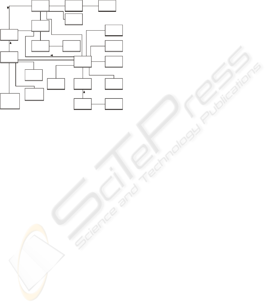
The Service Session Graph information model
The Service Session Graph (SSG) offers a ge-
neric framework to describe information in service
sessions and is used to model and control the state of
a service session. The capabilities modelled in the
SSG, which can be seen in Figure 7, are party invi-
tation and addition, stream binding and stream com-
position, and explicit control of the use of resources.
The SSG supports the definition of control relation-
ships through the ControlSR IO type. Additionally,
the SSG supports the definition of composing rela-
tionships through the CompSR IO type, which fa-
cilitates the representation of composition and fed-
eration of services. Finally, stream bindings are
modelled by the association of StreamInterface IOs
to StreamBindingSR IOs via the appropriate Ses-
sionMember IOs. The StreamFlowEndPoint IOs
have associated Quality of Service (QoS) attributes
and can be aggregated into stream interfaces at a
party’s end system or at a Resource IO.
Figure 7: The Service Session Graph information model
Taking into account the previous discussion, the
following actions take place when specifying the
ancillary service conceptual models:
• Customise the session related information models
(Figure 4) according to the service requirements.
• Customise the access session related information
models (Figure 5) according to the service
requirements.
• Customise the service session related information
models (Figure 6) according to the service
requirements.
• Customise the SSG information model (Figure 7)
according to the service requirements.
Provider Domain Access Session
Domain Session
TINA Session
Domain Session Bindi ng
Access Session
Domain Access Session
User Domain A ccess Session
Peer Domain Access Session
Doma in
Access Session
user / peer
provider / peer
Constraints
Doma in
Contract
A
ccess SessionService Session
User Profile
*
*
*
*
2
*
Con trols
Control s
*
*
Constraints
*
*
Request s
Control s
provider/peer
provider/
peer
0..1
(a) (b)
Domain Usage Service Session
Domain Sessio n
TINA Session
Domain Session B inding
Provider Service Session
Provider Domain Usage Service Session
Complement-of
Complement-of
Comple ment-o f
Domain Usage Service Sessio n Binding
User Domain Usag e Service Sessio n
Compose r Usage Service Session
Peer Doma in Usage Service Session
Service Session
Domain Usage
Service Session Binding
Domain
Member
Domain Usage
Serv ice Sessio n
Prov ider
Service S ession
Usage
Service Session
Con trols
*
Represe nts
*
Contr ols
2
2
party/ peer
provider/peer
***
1..*
*
2
Owns/
Supports
(a) (b)
Stream
BindingSR
ControlSRResource
SessionMember
SessionRelationship
Party
SessionMemberGroup
SessionRelationshipGroup
ServiceSessionGraph
OwnershipSR
PermissionSR
StreamInterface StreamFlowEndPoint
1..*
* *
** **
Peer
CompSR
*
*
Belongs-to
Participate-in
ICETE 2004 - GLOBAL COMMUNICATION INFORMATION SYSTEMS AND SERVICES
140

3.2 Definition of Service Sequence
Diagrams
Before proceeding to a logical design of how a
telematic service will work in terms of software
components, its behaviour is necessary to be exam-
ined and defined as a black box. In this way, service
behaviour is considered as a description of what the
telematic service does, without explaining how it
does it. One part of that description is service se-
quence diagrams.
A service sequence diagram should be done for
the typical course of events of each use case and
sometimes for the most important alternative
courses. It depicts, for a particular course of events
within a use case, the external actors that interact
directly with the telematic service, the telematic ser-
vice (as a black box), and the service events that the
actors generate. Time proceeds downwards and the
ordering of events should follow their order in the
use case. Service events (and their associated service
operations) should be expressed in an abstract way,
emphasising their intention, and not in an imple-
mentation specific manner.
Taking into account the above mentioned guide-
lines and remarks, this activity consists mainly of the
following steps:
Step 1:
Draw a vertical line representing the tele-
matic service as a black box.
Step 2:
Identify each actor that directly operates on
(or interacts with) the telematic service.
Step 3:
Draw a vertical line for each actor.
Step 4:
Identify the (external) service events that
each actor generates by examining the use case typi-
cal course of events text.
Step 5:
Illustrate the identified service events in the
correct order on the diagram.
Step 6:
Include (fragments of) the use case text to
the left of the diagram (optionally).
3.3 Definition of Service Operation
Contracts
The behaviour of a telematic service is further de-
fined by service operation contracts (or service con-
tracts), as they describe the effect of service opera-
tions upon the telematic service. A service sequence
diagram depicts the external events that an actor
generates, but it does not elaborate on the details of
the functionality associated with the service opera-
tions invoked. All the details that are necessary to
understand the service response (and thus the actual
service behaviour) are missing. These details are
included in service operation contracts, which de-
scribe changes in the state of the overall telematic
service when a service operation is invoked.
The creation of service operation contracts is de-
pendent on the prior development of use cases and
service sequence diagrams, and on the identification
of service operations (see Figure 3) in the following
order:
use cases Æ service sequence diagrams Æ service
operations Æ service operation contracts
More specifically, the use cases suggest the ser-
vice events and lead to the construction of the ser-
vice sequence diagrams. The service operations can
then be identified. The effect of the service opera-
tions is described in service operation contracts.
UML contains support for defining service contracts
by allowing the definition of pre- and post-condi-
tions of service operations (Evits, 2000).
The most important section is the “Post-condi-
tions” section which declaratively describes the state
changes that occur to service IOs in the service con-
ceptual model, using a number of suitably selected
statements (instance creation, instance deletion, at-
tribute modification, association formed, association
broken, and user interface activation). This section
reveals how the telematic service has changed as a
result of a specific service operation.
3.4 Definition of Service State
Diagrams
Service state diagrams can successfully describe the
legal sequence of external service events that are
recognised and handled by a telematic service in the
context of a specific use case. These are UML state
diagrams, which illustrate the interesting and signifi-
cant service events and the states of a telematic ser-
vice, together with the behaviour of the service in
reaction to a particular service event.
A service state diagram which depicts the
(overall) service events and their desired sequence
within a use case is called a use case service state
diagram, and can be created for a specific use case at
varying levels of detail depending on the exact mod-
elling needs. The real value of use case service state
diagrams is appreciated when they model complex
use cases with many service events, because then
they help considerably the service developer(s) dur-
ing the service design to avoid out-of-sequence ser-
vice events and the corresponding error conditions.
However, use case service state diagrams are not
necessary if there is no significant service event or-
dering. Therefore, their definition in the service
analysis phase is optional. In such cases, another
(optional again) alternative is the creation of a global
service state diagram, which illustrates, for the entire
telematic service, all the transitions for service
events across all the use cases. It is a union of all the
use case service state diagrams and is useful as long
INTEGRATING REQUIREMENTS & SPECIFICATIONS IN THE TELECOMMUNICATIONS SERVICE CREATION
PROCESS
141
as the total number of service events is small enough
to keep the diagram comprehensible.
Taking into account the above discussion, this
activity consists mainly of the following steps:
Step 1:
Draw a service state diagram for each use
case or (alternatively) draw a global service state
diagram.
Step 2:
Add to the diagram(s) transition actions,
transition guard conditions, and nested states
(optionally).
3.5 Complementary and Alternative
Approaches
In the service analysis phase, high level Object
Modelling Technique (OMT) diagrams can be used
to represent the service concepts and their relation-
ships. Additionally, analysis level Message Se-
quence Chart (MSC) diagrams can model the inter-
action among service parts. However, both these
OMT and MSC models provide a high level over-
view and an understanding of the service as a whole.
They do not focus to the individual service IOs. For
this purpose, quasi GDMO (Guidelines for the Defi-
nition of Managed Objects) and GRM (General Re-
lationship Model) can be used, with quasi GDMO
describing the characteristics of service IOs and
GRM specifying the relationships among service
IOs. Quasi GDMO and GRM are used for informa-
tion modelling purposes in TINA-C and originate
from the Open Systems Interconnection (OSI)
GDMO and GRM formal techniques that were de-
veloped for defining managed objects and their rela-
tionships. Finally, for the identification of service
concepts and service objects, for the assignment of
responsibilities to service classes, and for finding
and examining collaborations between service
classes, CRC (Class - Responsibility - Collaborator)
cards can be used. This simple but effective tech-
nique, assumes the existence of written requirements
specifications and is usable at both the analysis and
the design levels.
4 CONCLUDING REMARKS
The activities of the service analysis phase can be
seen in Figure 2 and the artifacts that are produced
in Figure 3. Service sequence diagrams and service
operation contracts are part of the service behaviour
model of the service analysis model (see Figure 8).
The service behaviour model specifies what service
events a telematic service responds to, and what re-
sponsibilities and post-conditions the corresponding
service operations have. Furthermore, it describes
the external interface and behaviour of the overall
service. It has to be noted that in order to be com-
plete (and really object-oriented) the information
specification of the service should also take into
account the (dynamic) behaviour of individual ser-
vice IOs. This behaviour is usually defined by allo-
cating operations to the service IOs. However, the
issue whether operations should be ascribed to indi-
vidual service IOs is quite controversial as it actually
represents a functional decomposition of the overall
service functionality (Choi, 2003)(Declan, 1997).
This clearly implies design decisions that should be
better taken at the service design phase.
Figure 8: The service analysis model
Finally, it has to be stressed that the proposed
service creation methodology (and thus its service
analysis phase) was validated and its true practical
value and applicability was ensured as it was applied
to the design and development of a real complex
representative telematic service (a MultiMedia Con-
ferencing Service for Education and Training,
MMCS-ET). More specifically, a variety of scenar-
ios were considered involving the support of session
management requirements (session establishment,
modification, suspension, resumption, and shut-
down), interaction requirements (audio / video, text,
and file communication), and collaboration support
requirements (chat facility, file exchange facility,
and voting).
In the service analysis phase, based on the ex-
panded use cases, the service conceptual model of
Figure 9 was created for the MMCS-ET. Use cases
suggest how actors interact with the telematic ser-
vice under examination. During this interaction an
actor generates events to the telematic service, re-
questing some operation in response. It is desirable
to isolate and illustrate the operations that an actor
requests from a telematic service (service opera-
tions) in service sequence diagrams, because they
are an important part of understanding service be-
haviour. Therefore, a service sequence diagram was
created for the typical course of events of each one
Service
Conceptual
Model
1
Use Cases
- High level
- Essential
Static Structure
Diagrams for
Service Domain
Concepts
1: static
model
2: dynamic
model
Notes
Service
A
nalysis
Model
Service
Analysis
Use Case
Model
2
Use Case
Diagram(s)
Service
Behaviour
Model
2
Service
Sequence
Diagrams
Service
Operation
Contracts
Service
Analysis
State Model
2
Use Case or
Global
Service State
Diagrams
ICETE 2004 - GLOBAL COMMUNICATION INFORMATION SYSTEMS AND SERVICES
142
of the identified use cases. Then, the effect of the
service operations that were revealed from the ser-
vice sequence diagrams was described in service
operation contracts.
Figure 9: The service conceptual model of the MMCS-ET
Considering all the artifacts produced in the ser-
vice analysis phase, three implementations of the
MMCS-ET were attempted. Initially, the MMCS-ET
was implemented using Microsoft’s Visual C++ to-
gether with Microsoft’s Distributed Component
Object Model (DCOM) (appropriately extended with
a high-level API in order to support continuous me-
dia interactions) (Adamopoulos, 2002) as a distrib-
uted object-oriented environment. The second im-
plementation was based on Microsoft’s .NET
framework using the C# programming language and
the third implementation exploited Java RMI / J2EE
together with CORBA. From these implementations,
a set of service engineering design patterns are de-
duced in various levels of detail, the applicability of
distributed object technology for service engineering
activities is examined and critical related perform-
ance matters are identified and addressed, and ex-
perience and insight is gained for the intended future
customisation of the proposed methodology for
wireless services and Web services.
REFERENCES
Adamopoulos, D.X., Pavlou, G., Papandreou, C.A., 2002.
Advanced Service Creation Using Distributed Object
Technology. In IEEE Communications Magazine, Vol.
40, No. 3, pp. 146-154.
Adamopoulos, D.X., Pavlou, G., Papandreou, C.A., 2002.
Continuous Media Support in the Distributed
Component Object Model. In Computer Communica-
tions, Vol. 25, No. 2, pp. 169-182.
Berndt, H., Hamada, T., Graubmann, P., 2002. TINA: Its
Achievements and its Future Directions. In IEEE
Communications Surveys & Tutorials, Vol. 3, No. 1.
Choi, S., Turner, J. Wolf, T., 2003. Configuring Sessions
in Programmable Networks. In Computer Networks,
Vol. 41, No. 2, pp. 269-284.
Declan, M., 1997. Adopting Object Oriented Analysis for
Telecommunications Systems Development. In Pro-
ceedings of IS&N ’97, LNCS, Vol. 1238, Springer-
Verlag, Berlin, pp. 117-125.
Evits, P., 2000. A UML Pattern Language, Macmillan
Technology Series.
Jormakka, J, Jormakka, H., 2002. State of the Art of Ser-
vice Creation Technologies in IP and Mobile Environ-
ments. In Proceedings of IFIP World Computer Con-
gress 2002, pp. 147-166.
Larman, C., 2002. Applying UML and Patterns: An
Introduction to Object-Oriented Analysis and Design
and the Unified Process, Prentice Hall.
TINA-C, 1997. Service Architecture, Version 5.0.
MMCS-ET
Provider
Profile
User
Subscription
Information
Contains
Supports
User
Directly
Communi-
catingUser
Information
Broadcasted
Message
Information
Exchanged
Message
Information
MMCS-ET
Service
Profile
User
Profile
User
Security
Catalog
Loggedin
User
Information
User
Security
Information
User
Subscription
Catalog
MMCS-ET
Session
Active
User
Information
Active
User
Information
Active
User
Information
Chat
Facility
Voting
File
Communi-
cation
Audio/Video
Communi-
cation
Stream
Binder
Audio/Video
Device
Te xt
Communi-
cation
Manages
Manages
Manages
1
*
1
0..10
1
0..10
1..*
Participate-in
1
1
1
Supported-by
Supports
1
1
1
1
Supports
1
1
Realised-by
Manages
14..*
11
1
1
Supports
1
1
1..*
Manages
1
1..*
1..*
1
1..*
1
Maintains
1
1..*
Initiates
1
Specifies
1
*
Manages
1
1
Maintains
11..*
Contains
1
1
Supported
-by
1..*
1
Characterised-by
Involves
11
Specifies
INTEGRATING REQUIREMENTS & SPECIFICATIONS IN THE TELECOMMUNICATIONS SERVICE CREATION
PROCESS
143
