
USING ECN MARKS TO IMPROVE TCP PERFORMANCE OVER
LOSSY LINKS
Haowei Bai
Honeywell Labs
3660 Technology Drive, Minneapolis, MN 55418, USA
Mohammed Atiquzzaman
School of Computer Science
University of Oklahoma, Norman, OK 73019-6151, USA
David Lilja
Department of Electrical and Computer Engineering
University of Minnesota, 200 Union St. SE, Minneapolis, MN 55455, USA
Keywords:
Wireless network, explicit congestion notification, TCP/IP, congestion control
Abstract:
TCP was designed for wireline networks, where loss events are mostly caused by network congestion. The
congestion control mechanism of current TCP uses loss events as the indicator of congestion, and reduces
its congestion window size. However, when a lossy link is involved in a TCP connection, non-congestion
random losses should also be considered. The congestion window size should not be decreased if a loss event
is caused by link corruptions. To improve TCP performance over lossy links, in this paper, we first present that
zero congestion loss could be achieved by appropriately setting the ECN marking threshold in the RED buffer.
Secondly, we propose a new TCP algorithm, called Differentiation Capable TCP (Diff-C-TCP). Diff-C-TCP
makes an assumption that packet losses are caused by link corruptions, and uses ECN (Explicit Congestion
Notification) to determine any loss that may occasionally happen due to network congestion. We have shown
that Diff-C-TCP performs very well in the presence of a lossy link.
1 INTRODUCTION
The TCP/IP (Transmission Control Protocol/Internet
Protocol) protocol was originally designed for wire-
line networks. Wireless links have a number of fun-
damentally different characteristics from wired links.
Wireless links are dominated by low bandwidth and
high error rates, which degrade the performance of
TCP (Bai and Atiquzzaman, 2003). In the current
TCP, the congestion control mechanism uses packet
loss as the indicator of congestion, and reduces its
congestion window size. However, when the packet
loss is caused by link errors rather than congestion,
TCP’s reduction of the congestion window size is un-
necessary and degrades its throughput.
In most cases, packet losses due to corruption are
more significant than congestion losses when a lossy
link is involved in a TCP connection. In such a case,
TCP may not be able to transmit or receive at the full
available bandwidth, because the TCP algorithm is
unnecessarily wasting time in slow-start or congestion
avoidance procedures triggered by link errors. Con-
sequently, the current congestion control algorithms
in TCP result in very poor performance over lossy
links. Significant performance improvements can be
achieved (Samaraweera and Fairhurst, 1998) if losses
due to network congestion and corruption in lossy
wireless links could be appropriately differentiated.
Researchers have applied heuristics, such as loss
predictors, to distinguish between congestion and er-
rors due to link errors (Biaz and Vaidya, 1997; Biaz
and Vaidya, 1998b), but their simulation results indi-
cated that their loss predictors did not perform well.
They proposed a modified TCP-Reno scheme called
TCP-Aware (Biaz and Vaidya, 1998a) to differentiate
between packet losses due to congestion and losses
due to link errors. However, their scheme works well
only when the last hop for the connection is wireless,
the bandwidth of the wireless link is much smaller
than the bandwidth of the wired link, and the overall
packet loss rate is small (Biaz and Vaidya, 1998a), all
of which are too limited in the real world Internet.
437
Bai H., Atiquzzaman M. and Lilja D. (2004).
USING ECN MARKS TO IMPROVE TCP PERFORMANCE OVER LOSSY LINKS.
In Proceedings of the First International Conference on E-Business and Telecommunication Networks, pages 437-445
DOI: 10.5220/0001405604370445
Copyright
c
SciTePress

Without any other additional information, the ex-
isting implicit loss feedback mechanisms in TCP does
not allow distinguishing between congestion and cor-
ruption losses (Dawkins et al., 2000). ECN (Explicit
Congestion Notification) (Floyd, 1994) was proposed
as an explicit indicator of congestion. It can be used
to quickly and unambiguously inform sources of net-
work congestion, without the sources having to wait
for either a retransmit timer timeout or three duplicate
ACKs (Acknowledgements) to infer a lost packet.
For bulk-data connections, this mechanism can avoid
unnecessary packet drops for low-bandwidth delay-
sensitive TCP connections, and can avoid some un-
necessary retransmit timeouts in TCP (Ramakrishnan
and Floyd, 1999). Since ECN is an explicit indica-
tor of network congestion, it provides the possibility
to differentiate two types of losses. If the buffer in a
router is optimally dimensioned and the RED (Ran-
dom Early Detection) threshold in the router buffer
is appropriately set, zero congestion loss could be
achieved by appropriately adjusting the source’s con-
gestion window size based on feedback from ECN
signals. Previous researchers (Kunniyur and Srikant,
2000; Liu and Jain, 2001a; Abouzeid and Roy, 2000)
have done some initial work in this direction as de-
scribed below.
Authors in (Kunniyur and Srikant, 2000) presented
a framework for designing end-to-end congestion
control schemes in a network where each user may
have a different utility function. They considered
ECN marks as an alternative to losses for conges-
tion notification. Using this model, they showed that
the ECN marking level can be designed to nearly
eliminate congestion losses in the network by choos-
ing the marking level independently for each node in
the network. However, the drawback of their work
is that they achieved zero congestion loss by over-
provisioning the network.
Authors in (Liu and Jain, 2001a) analyzed the
queue dynamics at the congested router, and derived
the closed-form formula and buffer requirements to
achieve zero loss and full link utilization. However, as
they stated in their work, they did not get the mathe-
matical expression for the average share of bottleneck
link bandwidth which is the most important parame-
ter of their model. Instead, they used simulation to il-
lustrate the relationship between the average share of
bottleneck link bandwidth and the Round Trip Time
(RTT). The same difficulty was also encountered by
authors in (Abouzeid and Roy, 2000). As a solution,
they introduced an unknown constant into the final ex-
pression.
Motivated by (Liu and Jain, 2001a; Abouzeid and
Roy, 2000), we derive the exact mathematical model
for the average share of bottleneck link bandwidth
by modeling the ECN marking dynamics as a Pois-
son Process. We finally end up with a comprehen-
sive mathematical model for achieving zero conges-
tion loss. The objective of developing the exact math-
ematical model was that, if we can eliminate all net-
work congestion losses in a heterogeneous network
environment involving lossy links, or if the conges-
tion losses are a small fraction of losses due to link
error, with negligible error all losses can be attributed
to random losses due to link errors. This observation
leads to our proposed Diff-C-TCP which is discussed
in detail in Section 3.2.
Diff-C-TCP assumes loss events indicate link cor-
ruption and uses ECN as congestion indication with
the precondition of zero congestion loss to differenti-
ate between congestion and corruption. As mentioned
earlier, because of link errors, packet losses due to
corruption is more significant in a lossy network. To
have a high TCP throughput when a TCP connection
traverses a lossy link, the TCP source should persist
in the previous utilization of bandwidth instead of re-
ducing the transmission rate when the loss is due to
corruption.
The contributions of this paper are as follows:
• We develop a comprehensive mathematical model
to calculate the value of the average share of bot-
tleneck link bandwidth. The model ensures zero
congestion loss in the network.
• Based on the possibility of zero congestion loss, we
Propose and evaluate a new TCP algorithm called
Diff-C-TCP to improve the performance of TCP
over lossy links.
The rest of this paper is organized as follows.
In Section 2, we present a comprehensive model to
achieve zero congestion loss with multiple compet-
ing TCP flows; the model is the basis of our pro-
posed Diff-C-TCP algorithm discussed in Section 3.
In Section 4, we describe the simulation methodol-
ogy that has been used to evaluate the performance of
our proposed algorithm. Performance improvements
achieved by our proposed algorithm as compared to
current TCP are presented in Section 5. Concluding
remarks are finally given in Section 6.
2 ELIMINATING CONGESTION
LOSSES WITH ECN
If the buffer in the router is optimally dimensioned
RED threshold is appropriately set, zero-loss conges-
tion control could be achieved by appropriately ad-
justing the source’s congestion window size based on
the notification by ECN.
In this section, we first describe the ECN mecha-
nism and provide the requirements for zero conges-
tion loss in two cases (Liu and Jain, 2001a), viz, one
ICETE 2004 - WIRELESS COMMUNICATION SYSTEMS AND NETWORKS
438

TCP connection and multiple competing TCP con-
nections, in Sections 2.2 and 2.3 respectively. The dif-
ficulty in using the zero congestion model is the cal-
culation of the average share of bottleneck link band-
width. In this section, we have solved that problem
by deriving the exact mathematical expression for the
average share of bottleneck link bandwidth, the most
important parameter in zero congestion loss model,
by modeling the ECN marking dynamics as a Pois-
son Process in Section 2.4. We finally end up with a
comprehensive mathematical model for achieving the
zero-loss TCP congestion control.
2.1 Analysis Assumptions
In order to set up a proper but not complicated model
and analyze the queue dynamics, as well as zero-loss
requirements, we make the following assumptions (as
used by authors in (Liu and Jain, 2001a; Liu and Jain,
2001b) for a similar model):
• Senders always have data to send and will send as
many as their windows allow.
• Receiver windows are large enough.
• There are no delayed acknowledgements.
• All packets have the same length.
2.2 Queue Dynamics Analysis with
One TCP Flow
Along the path with only one TCP connection, if the
bottleneck link bandwidth is µ packet/second, then
the downstream packet inter-arrival time and the ac-
knowledgement inter-arrival time on the reserve link
must be greater than or equal to
1
µ
(Liu and Jain,
2001a).
Based on this statement, we use the analytical
model shown in Figure 1 and notations as follows:
w(t) = The sender’s window size at time t.
r = Round Trip Time (RTT).
µ = Bandwidth of the bottleneck link.
t
s
= The time a packet needs to traverse from the
sender to the router.
T = The threshold of RED router.
ˆ
T = The optimum threshold of RED router for the
purpose of zero congestion loss.
P = The packet which increases the queue length
over T .
From (Liu and Jain, 2001a), we know that if at time
t the bottleneck link has been busy for at least r sec-
onds, and a packet just arrives at the congested router,
the queue length at the congested router is
Q(t) = w(t − t
s
) − rµ. (1)
S
R
T
P
t
s
r
r-t
s
u
Figure 1: Analytical model of one TCP connection.
Based on this theorem, requirements for achieving
zero congestion loss could be described by the rela-
tionship between the queue length and the threshold
of RED router. Results reported by authors in (Liu
and Jain, 2001a) for the two different phases, slow
start and congestion avoidance, are given below:
2.2.1 Slow Start Phase
The maximum queue length in slow start phase is
2T + rµ + 1.
2.2.2 Congestion Avoidance Phase
The maximum queue length in the congestion avoid-
ance phase is T + 1; the minimum queue length is
T −rµ+1
2
. To derive the optimal threshold for the RED
queue, the bottleneck link should be fully utilized,
i.e.,
T − rµ + 1
2
≥ 0, (2)
which means
T ≥ rµ − 1. (3)
However, if T > rµ − 1 indicating that the minimum
queue length is a positive number, the RED router
may have long queueing delays. Thus, the optimal
value of threshold (
ˆ
T ) for achieving zero congestion
loss, full link utilization and minimum queueing de-
lay in congestion avoidance phase can be calculated
from
T − rµ + 1
2
= 0. (4)
In other words, the optimal value of threshold is
ˆ
T = rµ − 1. (5)
Finally, we end up with various cases of possible
threshold as shown in Table 1.
2.3 Queue Dynamics Analysis with
Multiple competing TCP flows
Figure 2 shows the system model considered in this
section. We use the following notations in the analy-
sis:
USING ECN MARKS TO IMPROVE TCP PERFORMANCE OVER LOSSY LINKS
439
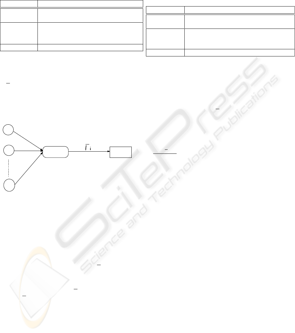
Table 1: Value of threshold T for the case of one TCP flow.
T Link Status
T > rµ − 1 The link is fully utilized, but packets suf-
fer larger queueing delay.
ˆ
T = rµ − 1 Optimal threshold; zero congestion
loss, full link utilization and minimum
queueing delay.
T < rµ − 1 The link is under-utilized.
w
i
(t) = The i
th
sender’s window size at time t.
r
i
= Round Trip Time (RTT).
µ
i
= The average share of the bottleneck link band-
width.
t
s
i
= The time a packet needs to traverse from the
i
th
sender to the router.
T = The threshold of RED router.
i
Router D
u
S1
Sm
Figure 2: Analytical model of multiple competing TCP con-
nections.
The analysis of the case of multiple competing TCP
connections is based on the discussion in Section 2.2.
For the analytical model shown in Figure 2, the queue
length expression given by (Liu and Jain, 2001a) is
shown below.
Q(t) =
m
X
i=1
(w
i
(t − t
s
i
) − r
i
µ
i
). (6)
As we mentioned in Section 1, the difficulty in using
Equation (6) is in calculating µ
i
. We show the calcu-
lation of µ
i
in Section 2.4.
Similar to the discussion in Section 2.2, we give the
requirements for achieving zero congestion loss for
two different cases, slow start phase and congestion
avoidance phase. These results are also reported by
authors in (Liu and Jain, 2001a).
2.3.1 Slow Start Phase
It is almost unlikely for multiple TCP connections to
send at the same time. If some connections are in slow
Table 2: The value of threshold T for the case of multiple
TCP flows.
T Description
T > rµ − 1 The link is fully utilized, but packets suf-
fer larger queueing delay.
µ − m ≤
ˆ
T ≤ rµ − 1
Optimal threshold; zero congestion loss,
full link utiliztion and minimum queueing
delay.
T < rµ − m The link is under-utilized.
start phase, while others are in congestion avoidance
phase, the queue length cannot be increased as fast as
all connections are in slow start phase. If all connec-
tions start simultaneously, this could be considered
as one aggregate flow. Accordingly, the maximum
queue length is still 2T + r
i
µ
i
+ 1.
2.3.2 Congestion Avoidance Phase
The maximum queue length in congestion avoidance
phase is T +α, α ∈ [1, m]; the minimum queue length
is
T −r
i
µ
i
+α
2
, α ∈ [1, m]. Three different threshold
values for the case of multiple TCP flows are shown
in Table 2.
2.4 Calculating the Average Share of
Bottleneck Link Bandwidth with
Multiple TCP Flows
In Section 2.2 and Section 2.3, we have summa-
rized the results of RED threshold and buffer size for
achieving zero congestion loss at a RED gateway as
described in (Liu and Jain, 2001a). However, they
did not obtain the quantitative value of the average
share of bottleneck link bandwidth (¯µ
i
in Equation
(6) which is the most important parameter in the zero
congestion loss model.
In this section, we show the calculation of the aver-
age share of the bottleneck link bandwidth. We con-
sider the system model shown in Figure 2 and the
Reno version of TCP. To keep the consistence, we use
all the assumptions we made for the previous model
in Section 2.2 and Section 2.3.
Figure 3 shows the window evolution approxima-
tion for TCP-Reno sessions with different round trip
delays sharing a bottleneck link with a RED gateway.
The loss events are represented by ’×’ marks. This
approximation has been used by many researchers
(Abouzeid and Roy, 2000; Abouzeid et al., 2000) for
the analytic understanding of the RED performance.
Based on Figure 3, we use the following notations in
our model.
ICETE 2004 - WIRELESS COMMUNICATION SYSTEMS AND NETWORKS
440

Window
size
Time
X1
X2
X3
W1,1
W1,2
W2,1
W3,1
W2,2
Figure 3: The window evolution approximation with two
TCP-Reno flows.
w
i,j
(t) = The j
th
TCP session’s window size right
before the previous loss event.
w
i+1,j
(t) = The j
th
TCP session’s window size
right before the current loss event.
w
j
avg
(t) = The time-average window size for the
j
th
TCP session.
r
i,j
= Round Trip Time (RTT) of the j
th
TCP ses-
sion.
µ
i
= Average share of the bottleneck link band-
width.
L
i
= The time when i
th
congestion loss event hap-
pens.
Consider the scenario in Figure 3; X
i
= L
i
− L
i−1
denotes the inter-loss duration. The window evolution
could be expressed by the following equation.
w
i+1,j
(t) =
w
i,j
(t)
2
+
X
i
r
i,j
. (7)
Since loss events are determined by both the traffic
type and the random marking at RED router, it is rea-
sonable to consider {X
i
} as an Independent Identical
Distributed (i.i.d.) renewal process. If we assume in
any length of time interval, the number of loss event
is Poisson distributed, then the total number of loss
events in the interval (0, t) is a Poisson process, de-
noted by N(t). Therefore, the loss time interval X
i
is
an i.i.d. exponential random variable with the param-
eter λ. Its probability density function (pdf) is
f
X
i
(t) = λe
−λt
u(t). (8)
In addition, the waiting time T [n] = Σ
n
k=1
X
k
for a
loss event is a gamma distributed random variable
with parameters (n, λ). Its pdf can be found as
f
T
(t) =
λe
−λt
(λt)
n−1
Γ(n)
u(t), (9)
which is, in the other form,
f
T
(t) =
λ
n
e
−λt
t
n−1
(n − 1)!
u(t). (10)
Based on the mathematical nature of the window
evolution we analyzed above, we finally calculate the
average share of bottleneck link bandwidth, which has
been defined as
µ
i
=
w
j
avg
(t)
r
i,j
. (11)
Taking the expectation for both sides of Equation (7),
we have
w
i+1,j
(t) =
w
i,j
(t)
2
+
X
i
r
i,j
. (12)
Since any two loss events have the same statisti-
cal characteristics, it is apparent that w
i+1,j
(t) and
w
i,j
(t) have the same expected value. Thus,
w
j
(t) = 2
X
i
r
i,j
. (13)
Recall that the loss time duration is a renewal process
and the total number of loss events during any length
of time interval is a Poisson process, from Equation
(8), we should have
X
i
= E[X
i
] =
1
λ
. (14)
Therefore,
w
j
(t) =
2
λr
i,j
. (15)
Because Poisson process is ergodic in mean (See
Appendix A for the proof), using the property of er-
godicity, we have
w
j
avg
(t) =
w
j
(t) =
2
λr
i,j
. (16)
Finally, the average share of the bottleneck link band-
width is
µ
i
=
w
j
avg
(t)
r
i,j
=
2
λr
2
i,j
. (17)
Remarkably, the above result implies that the con-
nection with the shortest RTT has the largest average
share, which is also found by authors in (Liu and Jain,
2001a; Mistra et al., 1999).
3 USING ECN TO IMPROVE THE
TCP PERFORMANCE OVER
LOSSY LINKS: DIFF-C-TCP
From the previous discussion, we can eliminate all
network congestion losses (or the congestion losses
are a small fraction of random losses) in a hetero-
geneous network environment involving lossy links.
Therefore, with the negligible error all losses can be
attributed to random losses. This leads to our pro-
posed Diff-C-TCP discussed in this section.
USING ECN MARKS TO IMPROVE TCP PERFORMANCE OVER LOSSY LINKS
441
3.1 Design Assumptions
Before we start to illustrate the principle of our pro-
posed Diff-C-TCP algorithm, we make the following
assumptions:
• Our proposed algorithm is used within a WAN or
an enterprise network, where it is possible to make
all routers and end-systems ECN-capable.
• When we mention wireless links, in order to keep
our discussion focused, we do not consider mobil-
ity issues such as handoff or power requirements.
3.2 The Proposed Diff-C-TCP
Our proposed algorithm assumes that packet losses
indicate corruption, and the TCP sender uses ECN as
an explicit notification of network congestion. Diff-
C-TCP’s response to ECN is similar to TCP’s re-
sponse to packet losses. In other words, the receipt
of ECN packets should trigger a response to network
congestion. Packet losses are treated as link errors
unless ECN packets are received.
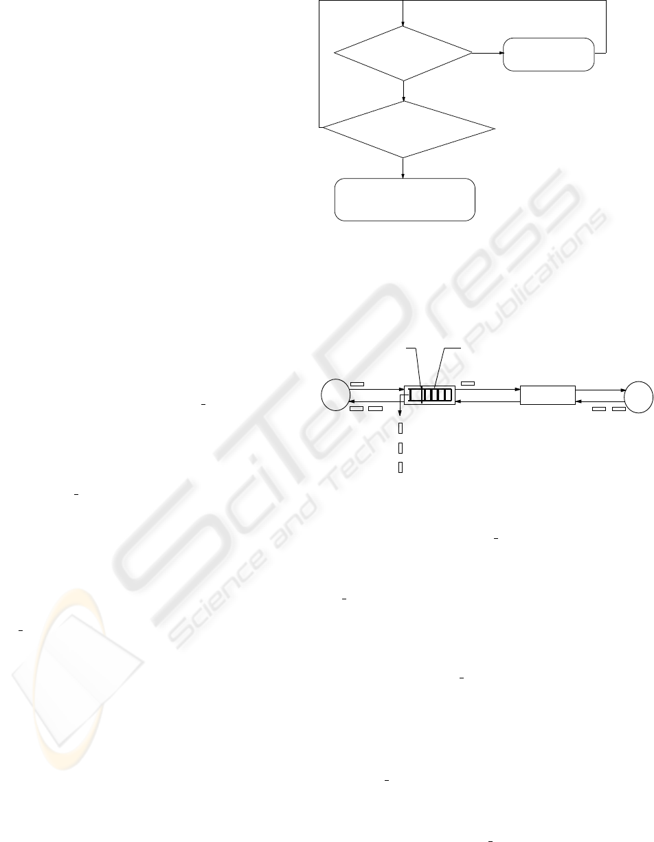
Figure 4 shows the kernel of our proposed Diff-C-
TCP algorithm at the sender’s side. A Diff-C-TCP
sender treats the situation that the retransmit timer
times out without receiving any ECN
ECHO packet
and (or) receiving duplicate acknowledgements as the
indication of link errors. Most often, this is the case
in a network with wireless links (packet losses due
to link errors). In this case, the Diff-C-TCP source
does not decrease cwnd. If the Diff-C-TCP sender re-
ceives the ECN ECHO packet sent by the receiver, the
sender treats it as network congestion and triggers the
Fast Recovery algorithm (Ramakrishnan and Floyd,
1999) as in the current TCP.
In Diff-C-TCP, the congestion window size is ap-
propriately controlled in the presence of either net-
work congestion or corruption. Congestion win-
dow is halved using Fast Recovery algorithm when
there is network congestion (explicitly notified by
ECN ECHO packets), and persists at the previous
value in the presence of corruption. There are two
mechanisms that might be applied to adjust conges-
tion window when Diff-C-TCP sender detects corrup-
tion: (i) keep cwnd unchanged as the previous value;
(ii) use Congestion Avoidance algorithm to slowly in-
crease cwnd. In our algorithm, we adapt the first
mechanism: make congestion window persist in the
previous value.
ECN mechanism will be most effective if it is used
with active queue management (such as RED) (Ra-
makrishnan and Floyd, 1999) as illustrated in Fig-
ure 5. In active queue management, when a buffer
reaches a certain threshold, the router will send a CE
packet to the TCP receiver. Routers send CE packets
before their buffers overflow. Therefore, packet drops
ECN_ECHO
Packet?
Time out/DUPACKs
(Assume corruption
happened)
DO NOT decrease the
congestion window size;
Retransmit loss packet
Fast Recovery
(W<=W/2)
Y
N
Y
N
Figure 4: States transition diagram of Diff-C-TCP kernel.
due to congestion happen only after the router has sent
CE packets. Upon receiving the CE packet, the TCP
S
D
Packet drops
due to buffer
overflows
CWR Packet
ECN_ECHO
Packets
CE Packet
Router
ECN_ECHO
Packets
Active Queue
Management
Threshold
Figure 5: A simple Diff-C-TCP based model.
receiver will keep sending ECN ECHO packet back
to the sender until it receives a CWR packet from the
sender, which means the sender has responded to net-
work congestion. The sender only responds to the first
ECN ECHO packet and ignores others up to one RTT.
3.3 Illustration of Diff-C-TCP
Depending on the threshold of RED and the level of
network congestion, ECN ECHO packets can arrive
at the sender either before or after the retransmit timer
times out due to congestion packet losses (caused by
buffer overflow). Our proposed Diff-C-TCP is effec-
tive in both the above cases as described below.
3.3.1 Case 1: Retransmit timer times out after
ECN ECHO packets are received by the
sender.
In this case, the sender will respond to congestion as
indicated by the receipt of ECN ECHO packets. This
case is desirable.
ICETE 2004 - WIRELESS COMMUNICATION SYSTEMS AND NETWORKS
442
3.3.2 Case 2: Retransmit timer times out before
ECN ECHO packets are received by the
sender.
In this case, as shown in Figure 6, the retransmit timer
timeout happens at time t
1
, and ECN ECHO pack-
ets are received by the sender at time t
2
. If the dif-
ference between t
1
and t
2
is small enough, though
the TCP sender does not respond to packet losses in-
dicated by retransmit timer timeout at t
1
(according
to our Diff-C-TCP), ECN ECHO packets will arrive
very quickly, which will trigger Fast Recovery mech-
anism to relieve the network out of congestion.
The difference between t
1
and t
2
can be decreased
by decreasing t
2
as described below. As mentioned
above, using active queue management such as RED,
when buffer reaches threshold, it will send the CE
packet to receiver. Upon receiving the CE packet,
the receiver starts to send ECN ECHO packets to the
sender. Though it is difficult to control the travel
time of ECN ECHO packets from the receiver to the
sender, we can make the receiver send ECN
ECHO
packets earlier by letting the router send the CE
packet earlier. The earlier ECN
ECHO packets are
sent, the earlier they arrive at the sender, i.e., the
smaller the value of t
2
is. The time when the router
sends the CE packet is decided by the value of thresh-
old. Therefore, an optimum value of RED’s threshold
is very important for the sender to receive congestion
notification quickly. Optimal RED threshold is one of
our current research topics.
0
time
t1 t2
t2-t1
Timeout
ECN_ECHO
Figure 6: Time sequence of Case 2.
4 SIMULATION
METHODOLOGY
We have evaluated the performance of our Diff-C-
TCP algorithm using the ns (ns Version 2.1b6) sim-
ulation tool from Berkeley (Berkeley/LBNL, 2000).
The ECN implementation is based on RFC 2481 (Ra-
makrishnan and Floyd, 1999). Our network topology
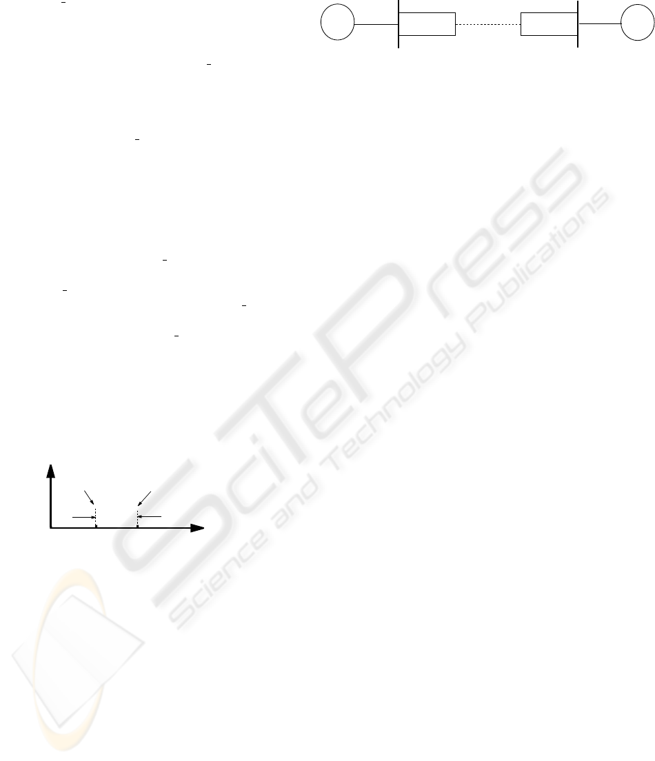
for conducting simulations is shown in Figure 7.
Two local area network (10 Mbps) are connected
using a lossy wireless link (64Kbps) with a propaga-
tion delay of 280ms. Like previous researchers (Bal-
akrishnan et al., 1997; Parsa and Garcia-Luna-
S D
Router A
Router B
10Mb, 2ms
64Kb, 280ms
10Mb, 4ms
LAN
LAN
Figure 7: LAN interconnection using a lossy wireless link.
Aceves, 1999), a Uniform random error model is used
to generate random errors on the wireless link. In-
stead of dropping packets at routers, RED routers are
used in our simulations to set the CE bit in the packet
header.
All the links in Figure 7 are labelled with a (band-
width, propagation delay) pair. The full-duplex link
between router A and router B has a BER (bit-error
rate), which varies between 1e
−7
to 1.2e
−4
in our
simulation. The receiver’s advertised window size,
which is also equal to the initial ssthresh at the sender,
is set to 30 segments. The packet size is set to 1000
bytes (when BER is below 5e
−5
) or 512 bytes (when
BER exceeds 5e
−5
). Ftp was used in our simulation
to transfer data from the source to destination.
5 SIMULATION RESULTS
In this section, we present and compare the goodput
(bit/s) (the amount of useful information being re-
ceived by the receiver per second, excluding errors)
and the normalized throughput of our proposed Diff-
C-TCP with the traditional TCP.
Figure 8 compares the goodput in bit/s of both Diff-
C-TCP and the current TCP with ECN capability. The
normalized throughput of both the TCPs are shown
in Figure 9. We see that Diff-C-TCP’s throughput is
much higher than that of the current TCP with ECN
capability. At a BER of 5e
−5
, the goodput of our Diff-
C-TCP is almost 5 times higher than that of the cur-
rent TCP. From Figures 8 and 9, this improvement
is much higher at higher values of BER. In addition,
the throughput of the current TCP with ECN suffers
more severely than our Diff-C-TCP as the error rate
increases. We can also see that, with the increase of
the value of BER, the throughput of the current TCP
with ECN capability decreases much faster than the
throughput of our Diff-C-TCP. For example, accord-
ing to Figure 8, when the value of BER increases from
1e
−5
to 5e
−5
, the current TCP’s goodput decreases
by 77 % in contrast to our Diff-C-TCP whose good-
put only decreases by 12 %. This is also valid for
normalized throughput as shown in Figure 9.
As mentioned previously, the current TCP with
ECN makes an assumption that every loss event is
caused by network congestion, and a congestion con-
USING ECN MARKS TO IMPROVE TCP PERFORMANCE OVER LOSSY LINKS
443

0 0.2 0.4 0.6 0.8 1 1.2
x 10
−4
0
1
2
3
4
5
6
7
x 10
4
BER
Goodput (bit/s)
Tahoe TCP with ECN capability
Diff−C−TCP
Figure 8: Comparison of goodput (bit/s).
0 0.2 0.4 0.6 0.8 1 1.2
x 10
−4
0
0.1
0.2
0.3
0.4
0.5
0.6
0.7
0.8
0.9
1
BER
Normalized Throughput
Tahoe TCP with ECN capability
Diff−C−TCP
Figure 9: Comparison of normalized throughput.
trol algorithm is triggered. As a result, the congestion
window size must be reduced. Therefore, each loss
event, regardless of whether it is due to congestion
or corruption, degrades the throughput. With Diff-
C-TCP, all packet losses are assumed to be caused by
link errors, and network congestion is indicated by the
receipt of ECN ECHO packets. The congestion win-
dow will not be changed in the presence of corruption
losses. Thus, only network congestion can affect its
throughput. Furthermore, for the current TCP with
ECN, a higher value of BER results in more packet
drops and more frequent reduction of the congestion
window. Because of this, higher values of BER re-
sult in high frequency of reduction of the congestion
window size. It is therefore almost impossible for the
congestion window size to reach a high value, even
during a non-congestion-loss period.
6 CONCLUSION
We have derived a comprehensive model for achiev-
ing zero congestion loss. Based on the possibility of
zero-loss congestion control, we proposed a new TCP
algorithm (named Diff-C-TCP) to improve the TCP
throughput in the presence of non-congestion related
losses in a lossy wireless environment. Diff-C-TCP
improves the network throughput by assuming that
all loss events are caused by link errors, unless the
network explicitly informs the sources of congestion.
Network congestion is explicitly indicated by the re-
ceipt of ECN ECHO packets.
The proposed Diff-C-TCP has been studied in de-
tail using simulation and has been found to signif-
icantly improve TCP performance in lossy wireless
links. Our simulation results have shown that we have
achieved up to 5 times throughput improvement, over
the current TCP with ECN for data transfer across a
typical wireless link with high bit-error rates.
A THE PROOF OF THE
ERGODICITY OF POISSON
PROCESS
Poisson process can be expressed as (See Figure 10)
t1
t2
t3
1
2
3
t
N(t)
0
Figure 10: Poisson process.
N(t) =
∞
X
0
u(t − T [n]). (18)
As mentioned in Section 2.4, T [n] =
P
n
1
X
k
is the
arrival time for a loss event. Because N(t) is a Pois-
son process, during any time internal length of t, say,
(0, t), the total number of events is Poisson distributed
with mean λt.
Define a random sequence Y [n] = the total number
of events happened in the time interval (0, t), accord-
ing to the above analysis,
E[Y [n]] = λt. (19)
ICETE 2004 - WIRELESS COMMUNICATION SYSTEMS AND NETWORKS
444

Then, according to Strong Law of Large Numbers,
lim
n→∞
1
n
n
X
k=1
Y [k] = λt. (20)
Thus,
lim
n→∞
1
n
n
X
k=1
Y [k] = λt = E[N (t)]. (21)
In other words, the time average is equal to the ex-
pected value. Therefore, Poisson process is ergodic
in mean.
REFERENCES
Abouzeid, A. and Roy, S. (2000). Analytic understanding
of RED gateways with mutiple competing TCP flows.
In GLOBECOM, pages 555–560, San Francisco, CA.
Abouzeid, A., Roy, S., and Azizoglu, M. (2000). Stochastic
modeling of tcp over lossy links. In INFOCOM, Tel
Aviv, Israel.
Bai, H. and Atiquzzaman, M. (2003). Error modeling
schemes for fading channels in wireless communica-
tions: A survey. IEEE Communications Surveys and
Tutorials, 5(2):2–9.
Balakrishnan, H., Padmanabhan, V., Seshan, S., and Katz,
R. (1997). A comparison of mechanisms for improv-
ing TCP performance over wireless links. IEEE/ACM
Transactions on Networking, 6(5):756–769.
Berkeley/LBNL, V. P. U. (2000). ns v2.1b6: Network sim-
ulator. http://www-mash.cs.berkeley.edu/ns/.
Biaz, S. and Vaidya, N. (1997). Using end-to-end statis-
tics to distinguish congestion and corruption losses: A
negative result. Technical report 97-009, Texas A&M
University.
Biaz, S. and Vaidya, N. (1998a). Discriminating congestion
losses from wireless losses using inter-arrival times at
the receiver. Technical report 98-014, Texas A&M
University.
Biaz, S. and Vaidya, N. (1998b). Sender-based heuristics for
distinguishing congestion losses from wireless trans-
mission losses. Technical report 98-013, Texas A&M
University.
Dawkins, S., Montenegro, G., Kojo, M., Magret, V., and
Vaidya, N. (2000). End-to-end performance implica-
tions of links with errors. draft-ietf-pilc-error-03.txt.
Floyd, S. (1994). TCP and explicit congestion notification.
ACM Computer Communication Review, 24(5):10–
23.
Kunniyur, S. and Srikant, R. (2000). End-to-end congestion
control schemes: Utility functions, random losses and
ECN marks. In INFOCOM, pages 1323–1332, Tel
Aviv, Israel.
Liu, C. and Jain, R. (2001a). Improving explicit conges-
tion notification with mark-front strategy. Computer
Networks, 35(2-3):185–201.
Liu, C. and Jain, R. (2001b). Improving explicit congestion
notification with the mark-front strategy. Computer
Networks, 35(2-3):185–201.
Mistra, A., Ott, T., and Baras, J. (1999). The window dis-
tribution of multiple TCPs with random loss queues.
In GLOBECOM, pages 1714–1726, Rio de Janeiro,
Brazil.
Parsa, C. and Garcia-Luna-Aceves, J. (1999). TULIP: A
link-level protocol for improving TCP over wireless
links. In WCNC, pages 1253–1257, New Orleans,
Louisana.
Ramakrishnan, K. and Floyd, S. (1999). A proposal to add
Explicit Congestion Notification (ECN) to IP. RFC
2481.
Samaraweera, N. K. G. and Fairhurst, G. (1998). Reinforce-
ment of TCP error recovery for wireless communica-
tion. Computer Communication Review, 28(2).
USING ECN MARKS TO IMPROVE TCP PERFORMANCE OVER LOSSY LINKS
445
