AUTOMATIC AUGMENTED VIDEO CREATION FOR
MARKERLESS ENVIRONMENTS
J. Sánchez and D. Borro
CEIT and TECNUN (University of Navarra)
Manuel de Lardizábal 15, 20018 San Sebastián, Spain
Keywords: Augmented Reality, Feature tracking, 3D Reconstruction.
Abstract: In this paper we present an algorithm to calculate the camera motion in a video sequence. Our method can
search and track feature points along the video sequence, calibrate pinhole cameras and estimate the camera
motion. In the first step, a 2D feature tracker finds and tracks points in the video. Using this information,
outliers are detected using epipolar geometry robust estimation techniques. Finally, the geometry is refined
using non linear optimization methods obtaining the camera’s intrinsic and extrinsic parameters. Our
approach does not need to use markers and there are no geometrical constraints in the scene either. Thanks
to the calculated camera pose it is possible to add virtual objects in the video in a realistic manner.
1 INTRODUCTION
The aim of Augmented Reality is to add computer
generated data to real images. This data goes from
explanatory text to three-dimensional objects that
merge with the scene realistically.
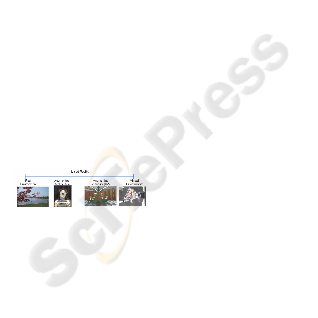
Depending on the amount of virtual objects
added to the real scene, Milgram et al. (Milgram, et
al., 1994) proposed the taxonomy shown in Figure 1.
Figure 1: Milgram taxonomy.
Mixed reality has proven to be very interesting in
areas like industrial processes, environmental
studies, surgery or entertainment.
In order to insert synthetic data in a real scene, it
is necessary to line up a virtual camera with the
observer viewpoint. Different options have been
tried, like magnetic, inertial trackers or other tracker
sensors. However, image based systems are
becoming the most interesting solutions due to their
lower cost and less invasive way of setup.
This paper presents a complete method for
authoring mixed reality videos using only image
information. Our implementation can calibrate a
pinhole camera, find a 3D reconstruction and
estimate the camera’s motion using only 2D features
in the images. The only constraint imposed is that
the camera must have constant intrinsic parameters.
2 STATE OF THE ART
Within the image based tracking solutions, there are
various possible choices, one or multiple camera
systems, but single camera solutions have become
more popular in last years.
For single camera configurations several pose
calculation algorithms has been proposed, such as
model, marker and feature based techniques.
The model based methods calculates the camera
transformation from the 2D projections of a known
3D model. A typical algorithm is POSIT
(DeMenthon & Davis, 1995). This algorithm has the
disadvantage that the known object must be always
in the image to be tracked.
Marker based systems consist in introducing into
the scene markers that the system can recognize.
These methods are fast and accurate but very
invasive too. One example is the ArToolkit library
developed in HITLab (Kato & Billinghurst, 1999).
Feature based algorithms have become more
important in recent years. They do not need any
markers in the scene or the presence of known
519
Sánchez J. and Borro D. (2007).
AUTOMATIC AUGMENTED VIDEO CREATION FOR MARKERLESS ENVIRONMENTS.
In Proceedings of the Second International Conference on Computer Vision Theory and Applications - IU/MTSV, pages 519-522
Copyright
c
SciTePress
objects but they are less accurate than other methods
and computationally more expensive. An example of
previous work in this area is (Cornelis, 2004).
3 PROPOSED ALGORITHM
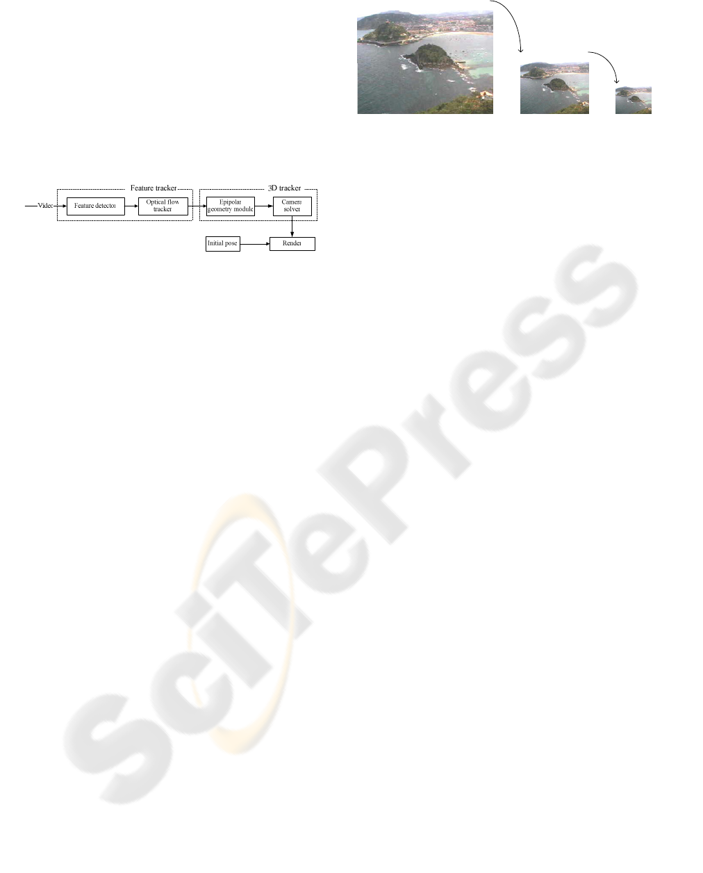
The method proposed includes a 2D feature tracker,
that finds and tracks features along the video, and a
3D tracker, that calculates the camera pose in every
frame. The algorithm can be seen in Figure 2.
Figure 2: Algorithm overview.
Initially, the feature tracker finds and tracks
corners in the video. Using the matched features, the
epipolar geometry can be found, allowing to
calculate the camera’s focal length and a 3D
reconstruction of the scene. Finally, the 3D motion
can be recovered from 3D-2D matches.
3.1 Feature Tracker
The algorithm used to find the features is based on
the GoodFeaturesToTrack proposed in (Shi &
Tomasi, 1994). It calculates the minimal eigenvalue
of the derivative covariation matrix for every pixel.
The threshold used to decide if a pixel corresponds
to a feature is chosen according to the number of
features detected in the image. The smaller this
number, the lower the threshold is set.
The corner detection only runs in the first frame
but it also should be carried out again if the number
of locked features decreases due to occlusions.
Once feature points are detected, the tracking
algorithm creates a history with their positions in the
next frames. Later, this information is used by the
3D tracker to estimate the geometry of the scene.
The method used is an iterative version of the Lucas-
Kanade optical flow proposed by Jean-Yves
Bouguet (Bouguet, 2000). This algorithm calculates
the displacement of a feature between two frames.
In order to obtain accuracy and robustness the
algorithm is executed iteratively in pyramidal
reductions of the original image as shown in
Figure 3. Low level pyramids (L
2
) provide
robustness when handling large motions, and high
level pyramids provides local tracking accuracy (L
0
).
0
L
1
L
2
L
Figure 3: Pyramidal reduction.
However, this method is very sensitive to noise.
In order to avoid this problem, a Kalman filter is
attached to each feature (Kalman, 1960), so
unexpected displacements can be detected. This
allows detecting outliers that could degrade the
reconstruction of the scene.
3.2 3D Tracker
This module solves the camera geometry and gets a
3D scene reconstruction using the tracked features.
All the processes involved in this module are based
on the epipolar geometry concept (Hartley &
Zisserman, 2000), thus the first step is to calculate
the fundamental matrix for every frame. Using this
initial approach, outliers are removed. Remaining
inliers are used to refine the fundamental matrix.
After this, the camera’s intrinsic parameters can
be found and an initial 3D frame can be set. Finally,
the camera pose can be calculated.
For the geometry estimation, Philip Torr’s
Matlab toolkit has been used (Torr, 2002).
Camera calibration is performed assuming a
standard pinhole model. Some constraints are
imposed in order to simplify the model, such
principal point centred in the image and no skew or
distortion.
The method used is a simplification of the
method proposed by Mendonca and Cipolla
(Mendonca & Cipolla, 1999). It is based on the
properties of the essential matrix.
The essential matrix is the fundamental matrix
for a calibrated camera. An important property of
this matrix is that it has two non zero and equal
eigenvalues. So, the proposed algorithm searches for
a calibration matrix that complies this property using
minimization techniques.
From the essential matrix, the pair of camera
matrices can be calculated using the method
described in (Hartley & Zisserman, 2000). The
reconstruction is performed by linear triangulation.
For every pair of frames there exists a possible
reconstruction, but only one is needed in order to
calculate the camera displacement. Any pair of
VISAPP 2007 - International Conference on Computer Vision Theory and Applications
520
frames can be chosen for this initial reconstruction
taking only one thing into account. If the two
selected frames are very near each other, the
reconstruction obtained is very poor because the
problem becomes ill conditioned (Cornelis, 2004).
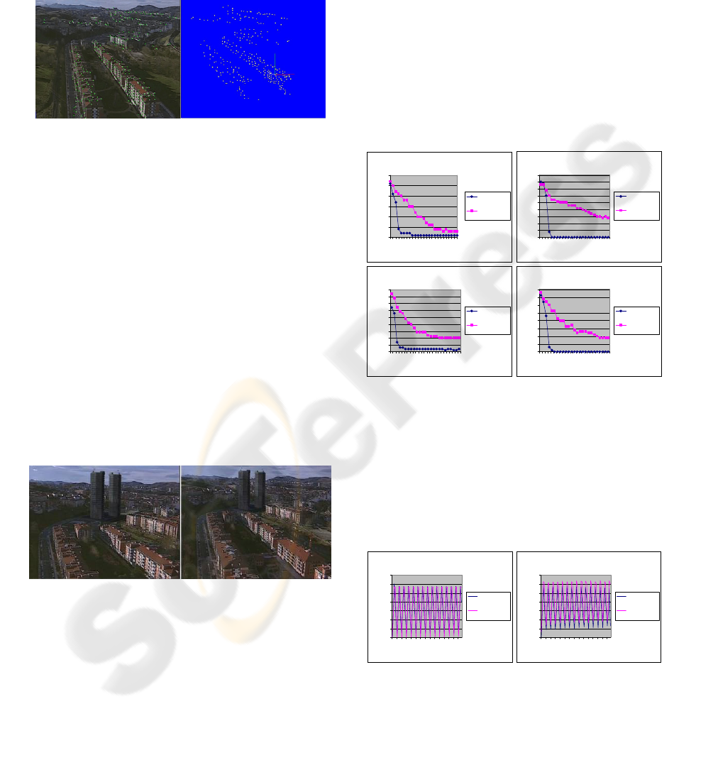
In Figure 4 an example of a 3D reconstruction is
shown. The left image is the original and the right
image shows the 3D points.
Figure 4: 3D reconstruction of the scene.
When the 3D structure is recovered, the camera
motion can be estimated. This can be achieved
performing a match between the reconstructed 3D
points and their corresponding feature points.
Using these matches, the DLT algorithm can be
used to calculate the rotation and the translation
relating the two frames. A minimum of six points
are needed, however, it is very typical to have
hundreds of matched 3D-2D features, so the best
solution is to take all the matches into account and
solve the problem using least squares.
When all camera transformations are known, the
only thing needed to render an object is a reference
coordinate system. The origin can be set in any of
the reconstructed features and then the user can
move the object manually to its initial position.
Figure 5 shows the final result of augmenting a
scene with two towers using the proposed algorithm.
Figure 5: Augmented scene.
There are some problems that have not been
considered yet, like occlusion or lighting. Real
objects sometimes cover or throw shadows to virtual
objects. This fact degrades the quality of the
resulting video, and will be addressed in the future.
4 EXPERIMENTAL RESULTS
This section evaluates the performance and precision
of the used algorithms. First, the feature tracker will
be evaluated using synthetic images and secondly
the camera tracker measuring the projection error.
The PC used in all the benchmarks is a Pentium
IV family 3.2GHz CPU with 1GB of RAM.
4.1 Testing the Feature Tracker
For testing the precision of the feature tracker we
have created an application that generates synthetic
images with known borders and additive noise.
For this test very noisy images are generated.
The next graphs show the evolution of the outlier
detection along the video sequence.
Standard deviation 70
0
5
10
15
20
25
30
1 4 7 101316192225
Frame
Outliers
Using Kalman
Without using
Kalman
Standard deviation 90
0
5
10
15
20
25
30
35
40
45
1 4 7 101316192225
Frame
Outliers
Using Kalman
Withot using
Kalman
Standard deviation 110
0
5
10
15
20
25
30
35
40
45
1 4 7 101316192225
Frame
Outliers
Using Kalman
Without using
Kalman
Standard deviation 130
0
5
10
15
20
25
30
35
40
1 4 7 101316192225
Frame
Outliers
Using Kalman
Without using
Kalman
Figure 6: Evolution of the outlier detection.
As we can see in the results, the Kalman filter
can detect practically all the outliers in four or five
frames in very noisy situations. The optical flow is
capable of detecting outliers as well but the results
are very poor for this application.
The optical flow calculation process also
introduces errors in the feature position. This error
has been measured in a moving scene:
Without noise
0
0,1
0,2
0,3
0,4
0,5
0,6
0,7
1 11213141516171
Frame
Error mean (pixels)
Using Kalman
Without using
Kalman
Standard deviation 50
0
0,1
0,2
0,3
0,4
0,5
0,6
0,7
1 11213141516171
Frame
Error mean (pixels)
Using Kalman
Without using
Kalman
Figure 7: Error in the tracking process.
Like can be seen in the graphs, the error
introduced by the optical flow is very small. This
fact combined with the efficiency reached in outlier
AUTOMATIC AUGMENTED VIDEO CREATION FOR MARKERLESS ENVIRONMENTS
521
detection, gives a reliable feature tracker for the 3D
reconstruction and camera pose estimation process.
The time for the whole feature tracking
algorithm is insignificant compared with the camera
solving process. For example, a video of 340 frames
with a resolution of 704x576 needs approximately 5
seconds to search and track 300 features.
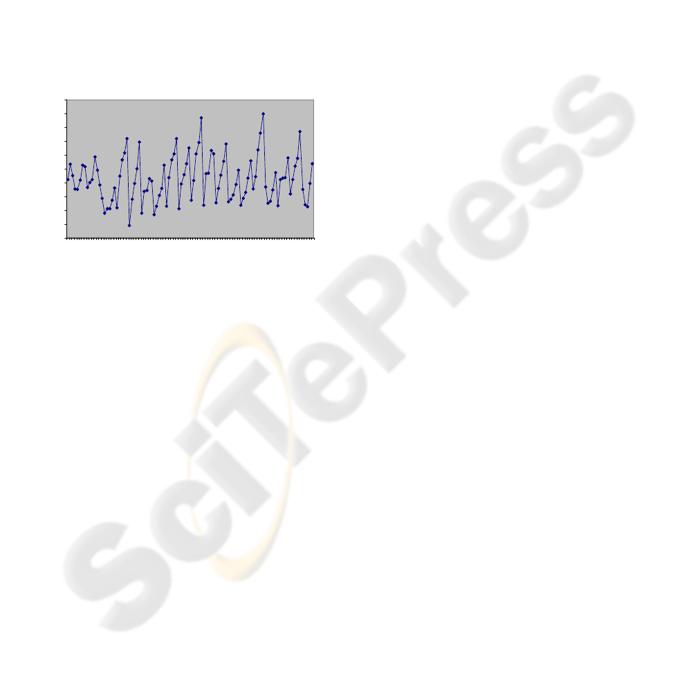
4.2 Testing the 3D Tracker
The strategy used to test the accuracy of the camera
pose estimation algorithm consists in comparing the
position of the features in the image with the
corresponding projections of the 3D points.
The next graph shows the mean of the error
measured along 100 frames.
0
0,05
0,1
0,15
0,2
0,25
0,3
0,35
0,4
0,45
0,5
1 6 11 16 21 26 31 36 41 46 51 56 61 66 71 76 81 86 91 96
Frame
Projection error (pixels)
Figure 8: Projection error.
The time needed to perform the 3D tracking
process is approximately one second per frame. This
is very far from the maximum of 40ms needed to run
the process in real time, but this is mainly because it
is implemented in Matlab.
5 CONCLUSIONS
This work covers all the processes involved in an
augmented video application. The method does not
need any knowledge of the augmented scene or user
interaction except in the registration step.
The advantage of this type of system is that any
video can be augmented imposing only a few
restrictions on it. Additionally, any user without
experience can augment videos in an easy way
because all the process is automatic.
In the first part of the work, a 2D feature tracker
has been developed. This tracker has proven to be
accurate enough for many applications, like 3D
reconstruction or camera pose estimation and it can
work in real time in a standard PC. This fact makes
the tracker suitable for surveillance, human
computer interaction or any application that needs
real time response.
Secondly, the designed 3D tracker can add
virtual objects to real videos. It depends heavily on
the accuracy of the feature tracker but the tests
demonstrate that the result is satisfactory under
normal conditions. On the other hand, actually the
prototype works under Matlab so the time needed to
run the tracker is very high. Thus, an immediate
objective is to translate the code into another
language, like C++. However, the proposed
algorithm is not proper for running in real time
because of the outlier search and the key frame
reconstruction based algorithm.
REFERENCES
Bouguet, J.-Y., "Pyramidal Implementation of the Lucas
Kanade Feature Tracker", Intel Corporation, Technical
Report 2000.
Cornelis, K., "From uncalibrated video to augmented
reality": Katholike Universiteit Leuven, 2004.
DeMenthon, D. & Davis, L., (1995). Model-Based Object
Pose in 25 lines of code. International Journal of
Computer Vision, 15, Pp. 123-141.
Hartley, R. & Zisserman, A., (2000). Multiple View
Geometry in computer vision: Cambridge University
Press.
Kalman, R., (1960). A New Approach to Linear Filtering
and Prediction Problems. Journal of Basic
Engineering, 82, Pp. 35-45.
Kato, H. & Billinghurst, M., (1999). Marker Tracking and
HMD Calibration for a video-based Augmented
Reality Conferencing System. In International
Workshop on Augmented Reality (IWAR), Pp. 85-94.
San Francisco, USA.
Mendonca, P. & Cipolla, R., (1999). A simple technique
for self-calibration. In IEEE Conference on Computer
Vision and Pattern Recognition, Pp. 112-116. Fort
Collins, Colorado.
Milgram, P., Takemura, H., Utsumi, A., & Kishino, F.,
(1994). Augmented Reality: A Class of Displays of the
Reality-Virtuality Continuum. In SPIE Conference on
Telemanipulator and Telepresence Technologies, Pp.
282-292. Boston, USA, October 31 - November 4.
Shi, J. & Tomasi, C., (1994). Good Features To Track. In
IEEE Conference on Computer Vision and Pattern
Recognition, Pp. 593-600. Seattle, Washington.
Torr, P., "A Structure and Motion Toolkit in Matlab",
Microsoft Research, Cambridge, UK, Technical
Report MSR-TR-2002-56, 2002.
VISAPP 2007 - International Conference on Computer Vision Theory and Applications
522
