
SIMULTANEOUS WIRELESS MEASUREMENT OF BLOOD
PRESSURE AND SYMPATHETIC NERVE ACTIVITY
A System for Investigating Neural Control Mechanisms in Long Term Blood
Pressure Regulation
Daniel McCormick
1
, Robert Kirton
1
, Alan Easteal
2
, Simon Malpas
1,3
, Carolyn J. Barret
3
Sarah Jane Guild
3
, Poul Nielson
1
, Augio Patrick Hu
4
, David Budgett
1
1
Auckland Bioengineering Institute,
2
Department of Chemistry
3
Department of Physiology
4
Department of Electrical and Computer Engineering, University of Auckland, Symonds Street, Auckland, New Zealand
Matthew Lim
Telemetry Research Ltd, PO Box 5504, Auckland, New Zealand
Bruce van Vliet
Division of BioMedical Sciences, Faculty of Medicine, Memorial University of Newfoundland, Saint John's, Newfoundland
Keywords: Telemetry, Inductively Coupled Power Transfer, Sympathetic Nerve Activity, Blood Pressure, Bio-
potential.
Abstract: We report on the development of a combined sympathetic nerve activity and blood pressure telemeter for
long term implantation in freely moving small animals. The devices simultaneously records and transmits
blood pressure, temperature and sympathetic nerve data on the 2.4 GHz ISM band with a range of 5 m.
Blood pressure is measured with a 400 Hz bandwidth, fluid filled catheter at a resolution of 0.1 mmHg.
Sympathetic nerve activity is measured differentially using stainless steel electrodes attached to the renal
nerve. The telemeter measures 29x37x12mm (a volume of approximately 9.5 cm
3
) and weighs 17g, making
it suitable for use in rats with a weight greater than 170 g. Battery life is 12 h when used continuously,
however the device’s lifespan is effectively indefinite due to the use of in vivo inductively coupled battery
charging. Example data recorded in a conscious unconstrained rat is provided which verifies the telemeters
operation.
1 INTRODUCTION
Elevated blood pressure is a well established factor
in determining an individual’s risk of developing a
number of serious diseases, including heart failure,
renal failure and stroke (Whelton and Klag 1989;
MacMahon 2000). Although the short-term
regulation of blood pressure is well understood, not
much is known about the regulation of blood
pressure over the longer-term.
Recently, with the development of long life
implantable telemetry, researchers have been able to
investigate the role of the sympathetic nervous
system in regulating blood pressure over longer time
periods and under more natural unconstrained
conditions. It is clear that the sympathetic nervous
system is key to the short term regulation of blood
pressure. However, much less is known about its
role in regulating blood pressure over long time
periods (Mark 1996). One method of investigating
this relationship is to measure the sympathetic
nervous system’s output directly by exposing nerve
fibre bundles and recording action potentials
directly. The level of sympathetic nerve activity
204
McCormick D., Kirton R., Easteal A., Malpas S., J. Barret C., Jane Guild S., Nielson P., Patrick Hu A., Budgett D., Lim M. and van Vliet B. (2008).
SIMULTANEOUS WIRELESS MEASUREMENT OF BLOOD PRESSURE AND SYMPATHETIC NERVE ACTIVITY - A System for Investigating Neural
Control Mechanisms in Long Term Blood Pressure Regulation.
In Proceedings of the First International Conference on Biomedical Electronics and Devices, pages 204-209
DOI: 10.5220/0001050902040209
Copyright
c
SciTePress

Table 1: A Comparison between two existing commercial
telemeters which are capable of measuring both blood
pressure and bio-potential signals (Data Sciences
International C50-PXT and Konigsberg T31F) and the
new type.
C50-PXT T31F New
LxWxH 30x15
1
33x15x10 29x37x10
Volume 6 5 9.5
Weight 11 13 17
#Bio Channels 1 2 1
Bio Bandwidth 1-100Hz
2
0.1-250 Hz
2
1-4 kHz
Pk-Pk Range Unknown 1 mV
3
120 μV
BP Bandwidth <100Hz
4
>1KHz 120Hz
Stability 5 mmHg 3 mmHg
2
T.B.D.
Batt Life 2 month 6 month 12 hour
5
#Trans Ch. 1 20 12
Trans. Type AM FM 2.4GHz
1. Cylinder (Length x Diameter).
2. Best estimate based on other devices made by the
manufacturer.
3. Smallest available input range.
4. Measured using frequency response rig.
5. Between charging.
(SNA) can then be compared with simultaineoulsy
aquired blood pressure measurements; allowing
researchers to experimentally investigate their
interaction.
Previously, researchers have had to implant two
seperate devices in order to record blood pressure
(Data Sciences International,St Paul, Minnisota) and
SNA (Telemetry Research, Auckland, New Zealand)
simutaineously over long periods of time (Barrett,
Ramchandra et al. 2003). This has meant that
research has typically been constrained to larger
animals such as rabbits. In this paper we present a
combined SNA and blood presssure telemeter that
can be implanted in animals as small as rats.
Figure 1: The SNA and BP telemeter.
Figure 2: Wireless charger (right rear) and charging pad
(foreground), implantable telemeter (on charger pad), and
analogue reconstruction units for pressure and SNA (left
rear).
Figure 1 shows the new experimental telemeter.
The leftmost leads are the nerve electrodes. At the
right is the fluid filled catheter for BP
measurements. Visible on top is the rechargable
lithium ion coin cell which provides power to the
telemeter between chargings. Inductive power
transfer is used to recharge the battery anytime while
still implanted. The electronics and electrodes are
incapsulated in medical grade silicon elastomer. The
telemeter measures 25x37x12mm (W x L x H,
excluding electrodes and catheter), occupies a
volume of approximately 9.5 cm
3
and weighs 17g,
making it suitable for use in rats with a weight
greater than 170 g (Moran, Roy et al. 1998).
Table 1 presents a summary of the specifications
of the new telemeter and its nearest comercially
available equivalents. These comparison devices
were chosen based on their size (small enough to be
used in a rat) and ability to measure both biopoential
signals and blood pressure. The major areas where
the new device differs from its equivelents are the
higher bandwith and sensitivity of the biopotential
ampifier, the abiltiy to recharge the new divice in
vivo and the use of a digital transmision system.
2 METHODS
2.1 System Architecture
The heart of the system is an 8051 microcontroller
which acts as an interface between the various
systems. An 8 channel (multiplexed) 12 bit A/D
converter is used to digitise recorded data. A bi-
directional transceiver operating on the 2.4 GHz
ISM band is used for communication, including data
transmission. This has a number of advantages
including the ability to wirelessly schedule
SIMULTANEOUS WIRELESS MEASUREMENT OF BLOOD PRESSURE AND SYMPATHETIC NERVE ACTIVITY
- A System for Investigating Neural Control Mechanisms in Long Term Blood Pressure Regulation
205
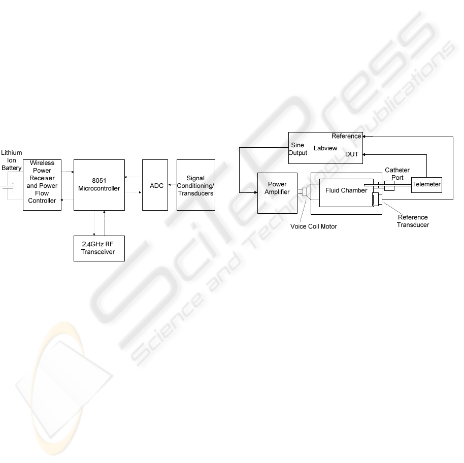
measurements in vitro. Additionally, 12 channels are
available for communication, allowing multiple
instrumented animals to be housed in close
proximity.
Power is provided wirelessly to the implant using
inductively coupled power transfer (Budgett, Hu et
al. 2007). This has allowed high power devices
(relatively speaking) such as A/D converters,
microcontrollers and digital transmission systems to
be used. During use, the implant can be charged by
placing a coil under the animal’s home cage through
which high frequency AC current is passed. Power is
received at the implant by a ferrite pickup which is
magnetically coupled to the charging coil.
Information about the charge state of the battery and
power received are embedded in the BP/SNA data
packets and transmitted to the wireless power
supply. The magnetic field can then be controlled
such that only the required amount of power is
delivered to the implant. This reduces the
temperature rise during charging to approximately
5°C.
Figure 3: Block diagram of the telemeter.
Between charging, a 70 mAH lithium ion coin
cell provides power. Consumption is 6 mA during
continuous operation which results in a battery life
of 12 h. In vivo charging takes between 2 and 4
hours and is dependent on how active the animal is
and how close the implant’s orientation is to the
optimum for charging. During charging SNA
recording is not possible as the nerve signal is
swamped by noise generated by the 200 kHz
charging field.
2.2 Blood Pressure Measurements
Blood pressure measurements are performed using a
10cm fluid filled polyurethane catheter, which acts
as an interface between the measurement site (for
instance the aorta) and the piezo resistive pressure
transducer in the telemeter. Pressure waveforms are
transmitted along the catheter using low viscosity
biocompatible fluid. No obvious reference pressure
is available internally to make measurements
against. Therefore, an absolute pressure sensor (one
with an internal vacuum reference) is used.
Physiologically, the pressure of interest is the
difference between the blood pressure and the
ambient or atmospheric pressure. This pressure is
derived by measuring the atmospheric pressure
using a second absolute transducer and subtracting it
from the internal pressure.
2.2.1 Frequency Response
Accurate measurements of systolic and diastolic
pressure require the use of a wide bandwidth
measurement system. One historical rule of thumb
is that the bandwidth should be greater than 10 times
the heart rate (Gabe 1972). For a rat, the maximum
heart rate that can be reasonably expected is 500
beats per minute. This requires a bandwidth of
greater than 80 Hz.
Figure 4: Frequency Response Measurement System.
In order to characterise the telemeters pressure
measurement bandwidth, the rig represented by
Figure 4 was constructed. A fluid filled chamber acts
as a pressure source for frequency response
measurements. Pressure waveforms are generated by
a voice coil actuator which exerts force on the fluid
through a thin brass diaphragm. The catheter of the
device under test (DUT) is inserted into the chamber
using a luer lock adaptor. A second high bandwidth
transducer provides a reference pressure for
calculations. Provided compliance of the chamber is
minimized, the system’s measurement bandwidth
can be high. Bandwidths of 5 kHz (-3 dB) have been
attained with usable signals present until approx
15 kHz.
Tests are preformed using the swept sine
technique where sinusoidal perturbations are applied
to the DUT. The LabVIEW Sound and Vibration
Analysis Toolbox (www.labview.com)
automatically calculates the magnitude transfer
function from reference pressure (P
ref
) to telemeter
output (P
T
) as defined by equation 1.
BIODEVICES 2008 - International Conference on Biomedical Electronics and Devices
206

A typical transfer function is presented in Figure
5. The bandwidth (-3 dB point) of the
catheter/amplifier combination (blue) is 400 Hz.
This is more that four times greater than the required
bandwidth of 80 Hz as described above. Gain
peaking is evident at around 100 Hz, but its
magnitude is exaggerated by the small vertical scale
and only amounts to a 15% increase in gain. The
small dip in magnitude at 50 Hz is due to power line
interference (in the test rig).After sampling at 500
Hz, transmission, reconstruction and filtering the
-3 dB frequency is reduced to 120Hz.
)(
)(
20)(
ω
ω
ω
jP
jP
LogjM
ref
T
dB
=
(1)
10
0
10
1
10
2
10
3
-50
-40
-30
-20
-10
0
10
Frequency (Hz)
Magnitude (dB)
Raw Amplifier Output
Reconstructed
Figure 5: Frequency Response of the blood pressure
measurement system. Amplified pressure sensor output
(blue) and reconstructed response after transmission (red).
2.3 SNA
2.3.1 The Nature of SNA
Postganglionic sympathetic nerves are composed of
multitudes of unmyelinated fibres. The action
potentials generated by individual fibres are small
and difficult to measure. Because of this, the entire
nerve bundle is usually used when recording SNA.
Typically two electrodes placed on the nerve and a
differential measurement is made. Measurable
voltages result as large numbers of fibres fire almost
simultaneously whose contributions are additive in
nature. Even so, the potentials generated by a whole
bundle are still only in the μV range. This, combined
with the relatively high frequency content of the
signals (into the kHz range (Malpas 1998)) make
instrumentation troublesome, and especially so in a
micro power telemetry system.
2.3.2 Signal Acquisition
Figure 6 shows the approach taken, which is
similar in nature to many previously described AC
coupled bio-potential amplifiers (Prutchi and Norris
2005).
Figure 6: Nerve Electrode Amplifier.
With a system gain of 10000 and a 3V power
supply, the amplifier is susceptible to saturation due
to electrode polarization offsets. Capacitively
coupling the active electrodes reduces the likely
hood of this happening but requires the use of a third
reference electrode. A low noise Instrumentation
amplifier (IA) amplifies and level shifts the signal
for analogue to digital conversion. A servo
amplifier monitors the DC level of the nerve signal
and centres it in the A/D converter’s range. This is
effectively a second form of AC coupling but also
improves headroom by reducing the effects of input
offset voltage. With a gain of 10000, the typical
input offset voltage of an instrumentation amplifier
(50 - 500 μV) could easily cause saturation.
Digitization is performed using a 12 bit A/D running
at 8 kHz. Full scale input range is ±60 μV. Intrinsic
noise is 650 nV
RMS
over the devices Bandwidth of
1 Hz-4 kHz. This results in a signal to noise ratio of
37 dB for a full scale sinusoidal input.
3 EXPERIMENTAL RESULTS
3.1 Experimental Procedure
Experiments were conducted in Wistar rats with
initial minimum weight of 250g and were approved
by the University of Auckland Animal Ethics
Committee (approval R543). The rats were housed
individually in standard rat cages, with food and
water available ad libitum. The room was kept at a
constant temperature (18 °C) and dark-light cycle
(lights on from 0600 to 1800).
SIMULTANEOUS WIRELESS MEASUREMENT OF BLOOD PRESSURE AND SYMPATHETIC NERVE ACTIVITY
- A System for Investigating Neural Control Mechanisms in Long Term Blood Pressure Regulation
207

Prior to implantation the implant was sterilized
in an 8% gluteraldehyde solution overnight and then
rinsed in sterile saline. The surgery was performed
using sterile procedures on a heated surgical table.
Anesthesia was induced by placing the rat in a
chamber filled with isoflorane, then a nose cone
arrangement was used to maintain the isoflorane
anaesthesia at a surgical level. An abdominal
incision was made and the abdominal aorta cleared
just above the iliac bifurcation. Using silk sutures
the aorta was temporarily occluded and a 23 gauge
needle used to pierce the aorta. The cannula of the
transmitter was inserted into the aorta and advanced
approximately 4cm. The cannula was secured in
place using cyanoacryalate adhesive and blood flow
restored. The body of the transmitter was placed in
the abdominal cavity, with the nerve electrodes and
ground electrode exteriorized, and the muscle
incision closed. A left flank incision was then made
and the electrodes tunneled under the skin to this
incision. A retroperitoneal incision was made
through the muscle and gentle retraction used to
expose the kidney. The renal nerve was found near
the renal artery and dissected free of the surrounding
tissue using fine forceps and visualisation under a
surgical microscope. The Teflon coating was
removed from the last 3mm of the electrode leads
and the stainless steel fashioned into small
hooks.The electrode leads were will be sutured to
the wall of the artery and the intact nerve placed
over the hooks. The nerve/electrode assembly is
insulated from the surrounding tissue using silicone
elastomer (Kwik-sil, World Precision Instruments).
The muscle layer was then closed, with the earth
electrode placed subcutaneously. Then both skin
incisions were closed with staples. As soon as a rat
regained consciousness it was returned to its home
cage. A heating pad was placed under the cage for
24 h after the surgery. Rats received buprenorphine
(Temgesic 1 μg/100 g) as an analgesic.
3.2 Results
Figure 7 is an example of data recorded from a
conscious unconstrained rat. The recording shows
the hallmark traits of SNA, with bursts of activity
occurring synchronously with the cardiac cycle
(Malpas and Ninomiya 1992). Evident in this trace
are small expiration related decreases in blood
pressure with a corresponding increase in the bursts
of renal sympathetic nerve activity illustrating the
arterial baroreflex response and its dependence on
renal sympathetic nerve activity (Dorward, Riedel et
al. 1985). BP recordings show good fidelity with a
crisp reproduction of the diastolic inflection without
ringing or undershoot. However, pulse pressure is
considerably lower than expected with a peak to
peak value of approximately 5 mmHg. The cause of
this is unknown, but may be due to the positioning
of the catheter or surgery trauma. Further
verification of the coordination between blood
pressure and SNA are shown in Figure 8 where 500
Figure 7: Example from one rat showing raw renal sympathetic nerve activity (top panel), rectified and integrated nerve
activity (middle panel) and arterial blood pressure (bottom panel) recorded whilst conscious over a period of 5 s.
0
1
2
3
4
5
Integrated
Sympathetic
nerve act
(uV)
80
85
90
95
100
0 0.5 1 1.5 2 2.5 3 3.5 4 4.5 5
time (s)
Arterial
Pressure
(mmHg)
-20
-10
0
10
20
Raw
Sympathetic
nerve act
(uV)
BIODEVICES 2008 - International Conference on Biomedical Electronics and Devices
208

ms intervals of blood pressure and SNA are
averaged using peak systolic pressure as a trigger
(similar to the triggering mechanism of an
oscilloscope). This figure illustrates that the renal
sympathetic nerve exhibited a clear cardiac related
rhythm.
4 CONCLUSIONS
An implantable telemeter which simultaneously
acquires blood pressure and microvolt level nerve
signals has been presented. The telemeter is of a
similar size to existing devices but posses many
advantages such as inductive charging, digital
transmission, and a high bandwidth microvolt input
range bio-potential amplifier. Future work will
concentrate on miniaturization and ascertaining the
long stability of the blood pressure measurement
system.
ACKNOWLEDGEMENTS
The authors wish to acknowledge the support of the
Circulatory Control Group, University of Auckland
and Telemetry Research Limited. Daniel
McCormick was supported by a New Zealand
Tertiary Education Commission Top Achiever
Doctoral scholarship.
REFERENCES
Barrett, C. J., R. Ramchandra, et al. (2003). "What Sets
the Long-Term Level of Renal Sympathetic Nerve
Activity: A Role for Angiotensin II and Baroreflexes?"
Circ Res 92(12): 1330-1336.
Budgett, D. M., A. P. Hu, et al. (2007). "Novel technology
for the provision of power to implantable
physiological devices." J Appl Physiol 102(4): 1658-
1663.
Dorward, P. K., W. Riedel, et al. (1985). "The renal
sympathetic baroreflex in the rabbit. Arterial and
cardiac baroreceptor influences, resetting, and effect of
anesthesia." Circ Res 57(4): 618-633.
Gabe, I. (1972). Pressure measurement in experimental
physiology Cardiovascular Fluid Dynamics. D.
Bergel. London, Academic Press: 11–50.
MacMahon, S. (2000). "Blood Pressure and the Risk of
Cardiovascular Disease." N Engl J Med 342(1): 49-52.
Malpas, S. C. (1998). "The rhythmicity of sympathetic
nerve activity." Progress in Neurobiology 56(1): 65-
96.
Malpas, S. C. and I. Ninomiya (1992). "A new approach to
analysis of synchronized sympathetic nerve activity."
Am J Physiol Heart Circ Physiol 263(4): H1311-1317.
Mark, A. L. (1996). "The sympathetic nervous system in
hypertension: a potential long-term regulator of
arterial pressure." J Hypertens Suppl 14(5): S159-65.
Moran, M. M., R. R. Roy, et al. (1998). "Size constraints
of telemeters in rats." J Appl Physiol 85(4): 1564-
1571.
Prutchi, D. and M. Norris (2005). Design and
Development of Medical Electronic Instrumentation.
New Jersey, John Wiley & Sons, Inc.
Whelton, P. K. and M. J. Klag (1989). "Hypertension as a
risk factor for renal disease. Review of clinical and
epidemiological evidence." Hypertension 13(5 Suppl):
I19-27.
Figure 8: Example from one rat showing renal sympathetic
nerve activity (top panel) and arterial blood pressure
(bottom panel) averaged over 500 ms synchronized using
peak systolic blood pressure.
60
70
80
90
100
110
120
Renal
Sympathetic
nerve act
(uV)
80
85
90
95
100
0 100 200 300 400 500 600
time (ms)
Arterial
Pressure
(mmHg)
SIMULTANEOUS WIRELESS MEASUREMENT OF BLOOD PRESSURE AND SYMPATHETIC NERVE ACTIVITY
- A System for Investigating Neural Control Mechanisms in Long Term Blood Pressure Regulation
209
