
JUST PUSH PRINT
Biodevice Printing Using Bioinks, Electroinks and Quantum Dot Inks
Jan Lawrence Sumerel and Kai Sudau
FUJIFILM Dimatix, Inc.,2230 Martin Avenue, Santa Clara, California 95050-2704, U.S.A.
Keywords: Ink jet, piezoelectric, biomaterials, microarray, bioink, electroink, quantum dot.
Abstract: Many advanced medical and environmental test devices require microscale patterning of cells, proteins, or
other biological materials, and the need for these devices to contain active functional material components
has increased dramatically. In addition, the biological material oftentimes requires an interface with an
electrical or optical output signal. Efficient production methods are paramount to meeting market demands,
and ink jet printing offers an easy, low cost alternative to materials deposition used in current biodevice
manufacturing. However, fluid development and proper printing parameters at the research level are
required for manufacturing processing and will be critical to process adoption. In this paper, operating
parameters and fluid characterization have been developed through processing biomaterials, organic and
inorganic conductive fluids and semiconductor nanoparticles. Because of the inherent versatility,
uniformity and scalability of this system, established operating parameters coupled with proper fluid
characterization will ultimately be translatable to production line systems of biodevice components.
1 INTRODUCTION
Biological monitoring devices and medical devices
generally have two material components used in a
stepwise fashion, a biological material that works as
both a reaction beacon and the biochemical reactive
site followed by an optical, piezoelectric or
electronic material that amplifies the signal to allow
a measurable readout of the reaction. Typically,
manufacturing protocols are distinct for each
component, but ink jet printing can be used for the
deposition of both materials. Interfacing processing
of these two components may be critical to
biodevice success, and electronic file pattern
formation allows component alignment. Ink jet
printing is inherently compatible to high throughput
(Antoniadis, 2007). Already, interesting
technological phenomena have spawned from the
patterning of structurally and functionally different
materials including high performance ceramics
Lewis, et al, 2006). For this reason, drop-on-
demand ink jet printing, a simple fabrication
process, has become a prominent player in materials
processing for biodevice components (Padinger,
2007). However, it is a big step for biodevice
developers to jump into robust in-line manufacturing
production systems. This type of equipment
requires a sizable financial investment plus
sufficient experience so that manufacturing
specifications and in-house knowledge can be
established. Thus, a low cost, easy-to-use laboratory
scale system is required for preliminary
experimentation. This strategy then allows substrate
evaluation, on-site development, and fluid
manufacturing to all occur simultaneously. This
need has been addressed with an R&D tool that
offers printhead maintenance, substrate alignment,
nozzle inspection and drop analysis, and ease-of-use
(Sumerel et al, 2006).
Just push print, the most common command for
the desktop printer, can now be used in the
laboratory or in manufacturing lines. Ink jet printing
is a simple and cost effective technique with
applications in the fields of electronics and
biomedicine and has been shown to have specific
applications in these industries (Sirringhaus et al.,
2000, Calvert, 2001, Haber et al., 2005). In contrast
to other multi-step production methods, ink jet
printing is an additive process that precisely deposits
metered quantities of fluid onto a variety of
substrates including glass, silicon, plastics, organic
thinfilms, and metals based on a user generated
pattern. The resolution of the printed pattern is
determined by a number of factors, including
297
Lawrence Sumerel J. and Sudau K. (2008).
JUST PUSH PRINT - Biodevice Printing Using Bioinks, Electroinks and Quantum Dot Inks.
In Proceedings of the First International Conference on Biomedical Electronics and Devices, pages 297-303
DOI: 10.5220/0001054902970303
Copyright
c
SciTePress

substrate/fluid contact angle, nozzle size, and lateral
resolution of the printhead (Song and Nur, 2004).
Ink jet printers can dispense fluid drops with
volumes in the picoliter (ρL) to microliter (µL)
range, and an integral step in bringing this
processing technique from the laboratory to
manufacturing systems is the development of
jettable fluids. The chemical properties of the fluid,
including density, surface tension and viscosity,
determine its jettability (Sumerel, et al., 2006).
During drop formation, energy is distributed
between the fluid’s viscous flow, surface tension,
and kinetic energy (Xu et al., 2005). The deposited
fluid volume is directly proportional to nozzle size.
This flexibility enables microscopic patterned
thinfilms of functional materials at a variety of
resolutions. The physical properties of the patterned
thinfilms (film thickness and pixel values) are
dependent on the fluids coupled with the drive
electronics of the printing device. In general, 2D
drawings, pictures or structures, formatted as a
bitmap image, can be translated into X and Y print
coordinates for materials deposition (drop-on-
demand). Each individual nozzle ejects a drop with
a ligament. The ligament and the drop coalesce
during flight to make a volumetric sphere and upon
contact with the substrate, the sphere alters its three
dimensional structure to become columnar. The
resulting printed image is a compilation of drops
where the third dimension is equal to film thickness,
a physical property that is dependent on particle
loading, drop spacing and drop spread. Once this
critical but iterative R&D phase of process and
material evaluation is complete to allow sustainable
ink jet printing, the fluids are scalable for production
use.
1.1 Ink Jet Printing Employing MEMS
Devices
The required heating process for thermal ink jet
printing (300°C) will damage thermally-sensitive
materials, thereby limiting their use in devising
functional devices (Calvert, 2001, Xu et al., 2005).
In contrast, using piezoelectric ink jet printing,
thermally sensitive materials are deposited under
ambient conditions. Piezoelectric printheads contain
a lead zirconate titanate (PZT) piezoelectric ceramic,
nozzles, and a fluid chamber. When a voltage is
applied to the PZT, mechanical vibrations create
acoustic waves that in turn force fluid out of the
chamber through the nozzles (Brünahl and Grish,
2002). Piezoelectric printheads are categorized
based on the deformation mode of the PZT (e.g.,
squeeze mode, bend mode, push mode, or shear
mode) (Myatt et al., 2006). MEMS fabrication has
increased the precision and resolution of the
deposited materials (Menzel, C., 2005). These
silicon devices increase jet-to-jet uniformity and
drop placement accuracy. The inertness of the
silicon expands the operating ranges to allow higher
chemical diversity and fluid throughput expanding
piezoelectric ink jet printing from the ability to print
graphic inks to the realm of printing functional
fluids required for biodevice manufacturing.
The ink jet printhead is powered by a
piezoelectric unimorph, which is constructed in the
plane of the wafer and consists of patterned PZT
bonded to a silicon diaphragm (Brünahl and Grish,
2002). The effective diameter of the nozzle is 21.5
mm; this nozzle size is approximated to generate 10
ρL drops. An important operating parameter of this
particular device is the negligible void volume due
to the direct fluid/printhead interface.
Fluid flow properties like low viscosities, low
boiling points, high surface tensions and non-
Newtonian behaviors are hallmarks of functional
materials and are also generally unfavorable
chemical characteristics for ink jet printing.
Manipulating the parameters that generate the
electronic signal to drive the movement of the PZT,
including its frequency, wave shape, wave duration
and voltage has provided a significant advancement
in printing an array of functional materials and has
been one of the areas of our research. The ability to
adjust the jetting parameters has been critical to the
success of printing bioinks and electroinks.
1.2 Functional Fluid Deposition
Thermal ink jet printing has been employed for the
deposition of biomaterials (Xu et al, 2005, Setti et
al., 2005). A glucose biosensor was fabricated by
thermal ink jet printing, and the enzyme, glucose
oxidase was made into a biological ink using
phosphate buffer and 10% glycerol (Setti et al.,
2005). In contrast to piezoelectric ink jet printing
where there are requirements for viscosity (8-14
centipoise (cps)) and surface tension (28-32
dynescm
-1
), most biological materials exhibit very
low viscosities (1 cps) and very high surface tension
values (60 dynescm
-1
). In addition, biological fluids
generate steam at high temperatures just like inks in
thermal ink jet printers. This heating process causes
bubble formation and fluid output at the nozzle plate
(Bae, et a., 2005). Major fabrication advances have
been made using thermal ink jet printing (Lemmo et
al., 1998) due to the low cost and wide availability,
BIODEVICES 2008 - International Conference on Biomedical Electronics and Devices
298

and at first glance this method should simplify
biomaterials deposition due to the looser
requirements for fluid formulation. However, the
thermal ink jet process may cause damage to
thermally-sensitive materials used in biology and
medicine. In contrast, piezoelectric ink jet printing is
a thermally constant process and does not require
heat thereby increasing the chances of biomaterial
stability.
Rapid detection employing microarray methods
are necessary to biomedical and chemical sciences
(Diehl, F., 2002). Miniaturization and automation of
arrays may lead to decreased costs and faster
analysis times (Peck, 2007). As drop sizes decrease,
feature sizes decrease and array densities increase.
Many forensic samples obtained in the field have
restricted amounts of recoverable material, and in
some cases, two polymerase chain reactions are
required to reach the levels of sensitivity and
verification required in the amplified
deoxyribonucleic acid (DNA) product (Vuorio et al.,
1990). Since piezoelectric ink jet printing only
requires 10 ρL per sample, the amount of DNA
needed for a precise polymerase chain reaction assay
is greatly reduced. For example, this technique may
provide an important advance in studying the
variation in a segment of mitochondrial DNA (a
non-coding region between two transfer ribonucleic
acid genes) (Salas et al., 2001). Variations in this
section of the gene is one obvious choice for
forensic identification because of sample number
(Wilson et al., 1995), and the predominant isolated
sample, human hair, shows low keratin protein
variation between individuals (Rodriguez-Calvo et
al., 1992). Unlike contact printing techniques (e.g.,
pin spotters) or expensive industrial ink jet
printheads, the single-use ink jet printhead
technology requires minimal deposition of fluids and
minimal cross-contamination (Manning, H., 2007).
The need for continual reiterations of circuit
design gestures for new approaches away from the
reductive process of masking and etching to create
metal patterns (Hwang, 2002) towards additive
processing. There are also market drivers for organic
electronic materials due to their adherence to
substrates, flexibility, performance and the ability to
process these materials at low temperatures (Shaw
and Seidler, 2001). Ink jet printing provides the
necessary technological platform to increase
throughput and lower processing costs. Indeed, low
capital costs, process simplicity, and flexibility have
been the important attributes that make this
technique practical for conductive trace patterning.
Many conductive precursor fluids are being jetted
using both thermal and piezoelectric ink jet printers
(Sirringhaus et al., 2000, Sawhney et al., 2006, Teng
and Vest, 1988; Volkman, et al., 2004). In fact, ink
jet printing is considered one of the key technologies
in defined polymer deposition (Sawhney, 2006).
Polymer structural confirmation varies with
temperature thus ambient processing conditions are
required. At low temperatures, typically below the
glass transition temperature (T
g
), polymers maintain
their natural, globular structure. At higher
temperatures, above the T
g
, they swell into open
conformations, essentially breaking their
entropically favorable π-π interactions (Baiesi et al.,
2001). With the conformational collapse, the
material becomes less conductive. In order to move
towards feasible ink jet manufacturing processes for
either conductive polymers or metallo-organic
fluids, initiating formulation, printing and post-
processing techniques are required. The fluids must
maintain solvent monodispersity; once printed, they
must properly adhere to the surface (Mei et al.,
2005). These criteria are integral for successful
printing, for even the smallest amount of
discontinuity will make the material non-conductive
and lower its mechanical strength.
Early attempts at ink jet printing silver metallo-
organic fluids capitalized on its advantageous
annealing temperature post-printing (200°C). The
resultant silver conductive traces on a variety of
materials including flexible substrates and substrates
are left with a low thermal budget (Volkman et al.,
2004). The direct writing of silver ink onto a grid
pattern of solar cells has been previously done using
a self-built printer and a Siemens ink jet printhead
(Teng and Vest, 1988). They modified their
printhead by machining restrictive nozzle plates that
varied drop size. The printer was run between 100
and 200 Hz which resulted in a printing speed of a
few cmsec-1. This single laboratory technique was a
slow throughput process and required multiple
printing cycles for effective deposition, so although
it is not agreeable to manufacturing protocols, it was
an important proof of concept step.
The choice of additional organic material in the
starting fluid greatly influences the obtained
conductivity (Mei et al., 2005). Once printed, the
silver in the fluid must be annealed to convert the
nanoparticles to a bulk silver thinfilm so that the
resistance values can closely mimic bulk silver. The
resulting amount of silver per volume of fluid is
controlled by the annealing temperature cycle
controls, and the effect of the organic decomposition
into the gas phase during annealing determines the
porosity of the printed material, which affects its
JUST PUSH PRINT - Biodevice Printing Using Bioinks, Electroinks and Quantum Dot Inks
299
continuity (Mei et al., 2005). Additionally, the
proper jetting parameters required for high
performance printing is fundamental for
reproducible deposition. The final feature size of the
material on the substrate is determined by these
parameters, and the overall conductivity is
established according to the applied thermal
processing (Mei et al., 2005).
2 MATERIALS AND METHODS
Proteins were dissolved in phosphate buffer saline
solution (Fisher Scientific, Fair Lawn, NJ, USA) and
1.6 µM solution. 1 % of polysorbate 20 surfactant
(Fisher Scientific, Fair Lawn, NJ, USA). 10 mg/mL
of human genomic DNA was dissolved in 50%
ethanediol.
Two percent (2%) glycerol (Sigma Aldrich, St.
Louis, MO) was added to a poly (3,4-
ethylenedioxythiophene) poly(styrenesulfonate)
(PEDOT/PSS) aqueous dispersion (H.C. Stark,
Goslar, Germany). ANP Silverjet nanopaste
(Advanced Nanoproducts, Chungcheonguk-do,
Korea) and Cabot Inkjet Silver Conductor (Ag-Ij-G-
100-S1, Albuquerque, NM) were used as packaged.
Fluids were sonicated in a water bath in a Branson
1510 sonicator at room temperature using highest
sonic level for 30 minutes. Fluids were degassed for
2 hours at 5 mbar pressure in a degassing chamber.
Quantum dots were obtained from UT Dots
(Savoy, IL, USA) and were serially diluted in 53%
polypropylene glycol 400, 45% propylene carbonate
solution containing 0.01% tetramethyl-5-decyne-4,6-
diol, 2,4,7,9-propanol (Surfynol 104PA; Air
Products, Allentown, PA).
Clean glass wafers were purchased from VWR
(VWR Scientific, West Chester, PA). Both Kapton
®
(Dupont, Wilmington, DE) and Teslin
®
synthetic
thinfilms (PPG Industries, Pittsburgh, PA) were kept
clean after purchasing and cut into 8 x 11 inch sheets
using laboratory scissors that had been cleaned with
70% ethanol (Sigma-Aldrich, St. Louis, MO).
Single-side polished 150 mm silicon 100 wafers
were obtained from Silicon Quest International
(Santa Clara, CA) and sputtered with 300 nm gold
layer using an Au target and a converted TES
sputterer.
The DMP-2831 (FUJIFILM Dimatix, Santa
Clara, CA) was used according to packaging
instructions. Contact angle measurements were
carried out using a VCA Optima XE (AST,
Billerica, MA). 2 µL samples were manually
pipetted for the measurements.
Scanning electron micrographs were obtained
using a Philips XL30 ESEM. Resolution was
obtained based on operating voltage of 5 kV.
Tapping mode AFM was conducted on a Digital
Instruments Dimension 3100 using an etched silicon
tip with a nominal radius of curvature of 10 - 20 nm.
Scan sizes were varied, depending on the feature
size. The scan rate was 0.1 - 0.3 Hz. The set point
was set to 60 - 70% of the free-standing root mean
square of the voltage of the oscillating tip.
Resistance measurements were obtained using a
Fluke 110 True RM multimeter. Anode was put at
one end of silver contact on glass wafer and cathode
was placed on top of other end of silver contact.
Electrodes were manually held during
measurements.
3 DISCUSSION
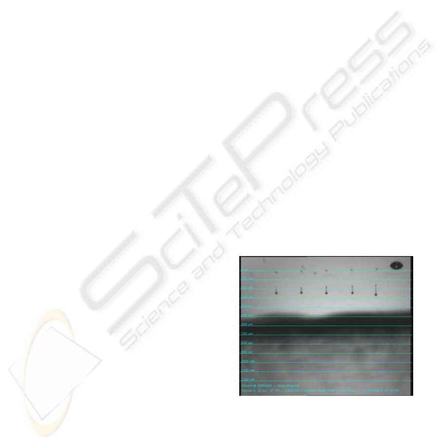
Both DNA and proteins were ink jet printed after
fluid formulation trials. Human genomic
deoxyribonucleic acid was printed in 10 ρL of 50%
ethanediol in the bottom of a 384 well assay plate or
onto a silicon wafer in a 254 µm grid with high
fidelity drop formation and uniform drop speed
(Figure 1). The high surface tension of the DNA in
water was mediated by the lower surface tension of
the 1,2 ethanediol (47 dynescm-1) but the short
ligaments in Figure 1 demonstrated how the surface
tension of the fluid is still the predominant force in
drop formation.
Figure 1: Deoxyribonucleic acid leaving the nozzle plate.
The only way to successfully print this fluid was by
lowering the jetting frequency and extending the
wave pulse from 11.52 µs to 14.1 µs. After
successful printing, the samples were air-dried and
tested for polymerase chain reaction amplification.
A 750 base pair fragment was resolved on a 1.2%
BIODEVICES 2008 - International Conference on Biomedical Electronics and Devices
300
agarose gel and visualized using ethidium bromide
(data not shown). These successful results suggest
that a significant cost savings may be obtained by
using piezoelectric ink jet printing for the detection
of clinically or environmentally relevant DNA
species.
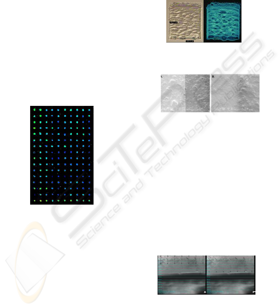
In general, globular proteins are stable in
phosphate buffered saline with a small amount of
non-denaturing detergent. We employed 1 % of
polysorbate 20 surfactant, a detergent that is often
used in protein purification due to its biochemical
compatibility and protein stabilization (Sumerel et
al., 2001). It has a second chemical attribute that it
lowers the surface tension of the fluid. Bovine
serum albumin was printed in 10 ρL drops, and then
an α-BSA polyclonal antibody (Sigma Aldrich, St.
Louis, MO) labelled with Cy3 was printed in
random array over the protein drops. The protein
array is shown where the antibody/antigen reaction
is shown in green and protein alone is shown in blue
(Figure 2).
Figure 2: BSA protein incubated with a-BSA polyclonal
antibody labelled with Cy3.
Due to appropriate fluid formulations required for
ink jet printing, glycerol was added to the stock
PEDOT/PSS solution to increase fluid viscosity. A
waveform was employed for successful PEDOT/PSS
printing (maximum jetting frequency of 1.0 kHz for
a pulse width of 17.0 µs). This waveform is a
critical parameter for jetting this particular fluid.
The applied voltage was tuned specifically for
each nozzle to provide uniform jetting speed to
ensure reproducible drop volumes. Images of the
jetting fluid were captured by light micrographs
using this camera and software system (Figure 3).
In panel A, the fluid is leaving the nozzle with the
ligament still evident. In panel B, at 500 µm, the
ligament has drawn into the drop, and the fluid is
flying towards the substrate at 9.25 msec-1, ten
times faster than the homebuilt printer discussed
above (Teng and Vest, 1988). The resulting
PEDOT/PSS on a silicon wafer pattern is shown
(Figure 4). The PEDOT/PSS spreads on an
untreated glass wafer with a contact angle of 18°
(data not shown).
Figure 3: Light micrographs of fluid jetting from printhead
nozzle and time of flights. A. Fluid leaving nozzle. B.
Drop formation at 500 µm.
Figure 4: PEDOT/PSS printed on silicon wafer. A. Bright
field. B. Dark field + UV.
Reliable printing procedures for two commercially
available conductive silver precursors have been
examined. Both fluids have ideal fluid flow
properties for ink jet printing and have higher than
50% silver nanoparticle load. The viscosity and
surface tension values of the ANP Silverjet
nanopaste are 9 cps and 26.5 dynescm-1
respectively. This fluid jetted at a maximum
frequency of 5.0 kHz with a pulse width of 13.2 µs.
Because of its high particle load (54%) and
uniform particle size as demonstrated by
transmission electron microscopy, low-temperature
annealing produces a traceable conductivity in the
printed material. Scanning electron micrographs
were obtained of the annealed printed nanoparticles
to compare the films produced (Figure 5).
Figure 5: Electron micrographs of ANP silverjet nanopaste
on Teslin
®
. Before annealing. B. After annealing.
Panel A shows the ANP Silverjet nanopaste on
Teslin
®
before annealing (silver on left, Teslin
®
on
right). With single-pass printing, the fluid makes a
JUST PUSH PRINT - Biodevice Printing Using Bioinks, Electroinks and Quantum Dot Inks
301
uniform film on the Teslin
®
substrate in spite of the
material’s surface roughness (Panel A). Figure 5,
panel B shows the same film on the same substrate
after annealing for 1 hour at 200°C (annealed silver
on left, Teslin
®
on right). Not only do the edges
look slightly more uniform, but full coverage of the
film on the substrate with single pass printing
created a very thin silver full coverage film on the
Teslin
®
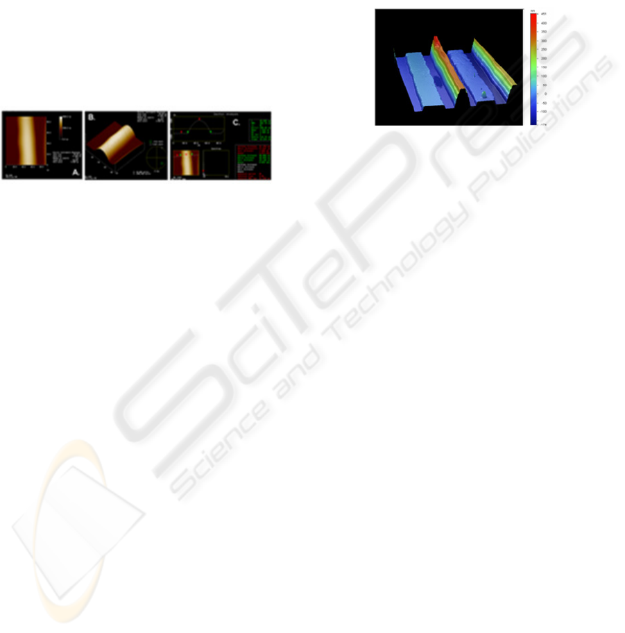
. Because accurate feature measurements are
difficult on flexible substrates, feature thickness was
measured on gold-coated polished silicon nitride
wafers (contact angle 41.8º, data not shown). We
measured feature sizes using atomic force
microscopy (AFM) with features printed at 20 mm
drop spacing. Figure 6 shows the overall scan area
of a single row of drops (Panel A).
Figure 6: Atomic force microscope images of single row
of ANP silver nanopaste drops. A. Overall scan area of a
single row. B. 3D rendering C. Feature measurements.
The three-dimensional rendered view in Panel B
shows the overall jetting uniformity. Panel C shows
the calculated feature measurements. The width of
the feature was 40.6 µm, and the film thickness of
1.59 µm demonstrates the utility of producing
patterned thinfilms using ink jet printing technology.
Because electrical performance is often described in
terms of the bulk resistivity, resistance values were
measured after annealing the silver nanoparticles.
The resistance of the ANP Silverjet nanopaste is
1.1Ω, and the resistance of the Cabot Inkjet Silver
Conductor is 0.3Ω (data not shown). The low
resistance measurements in both cases were taken on
equally-sized patterns on identical glass wafers.
These values are in the same range as resistance
values obtained by Sawhney and colleagues.
In order to achieve even finer features in
manufacturing electronic applications, drop volumes
below 10 ρL are required. Employing 1 ρL
printheads, the reduced drop volume will produce 20
µm silver fluid features on Kapton
®
employing the
ANP Silverjet nanopaste fluid. The miniaturization
of drop volumes is demonstrated by ink jet printing
with the 10 ρL cartridge followed by ink jet printing
with a 1 ρL cartridge on the same wafer substrate
and performing scanning electron microscopy (data
not shown) where the radius of the 1 ρL feature is
more than twice as small as the radius of the 10 ρL
feature. Smaller drop volumes will lead to fine
conductive traces required for appropriate feature
sizes in photovoltaic and electronic applications and
directly address market demands.
Quantum dots were diluted in 53%
polypropylene glycol 400, 45% propylene carbonate
solution containing 0.01% tetramethyl-5-decyne-4,6-
diol, 2,4,7,9-propanol and printed onto a clean
silicon wafer (Figure 7) using an optimized
waveform.
Figure 7: Scanning atomic force image of quantum dots
printed on silicon wafer.
Although these particles are identical in synthesis
methods and solvent composition, their
concentration had a radical effect on their deposition
on a silicon wafer substrate. The 2.6 nm quantum
dots spread on the substrate whereas the 4.0 nm
quantum dots did not spread to the same extent. The
thinfilm produced by the 2.6 nm quantum dots was
only 50 nm thick whereas the thinfilm produced by
the 4.0 nm quantum dots was about 450 nm strongly
suggesting that contributions to the final 3D
structure of the thinfilm are particle-concentration
dependent.
4 CONCLUSIONS
The software interface and waveform tuning allowed
fluid process development for a scalable ink jet
printing process. Ink jet printing of biologically
active, electronic and semiconducting materials is a
cost-effective manufacturing process. The printing
parameters for these materials have been
demonstrated, and the resulting interaction with the
substrate demonstrates that ink jet printing is an
iterative process where the interplay between the
chemical properties of the fluid, the cartridge
assembly, the machine operating procedure, the
substrate and post-ink jet processing all determine
whether this process is viable. Printing of two silver
nanoparticle fluids has demonstrated the flexibility
of the Dimatix Materials Printer, and these silver
nanoparticles were successfully processed into
conductive traces. Fluid formulation and ink jet
BIODEVICES 2008 - International Conference on Biomedical Electronics and Devices
302

printing operating parameters are both key to the
success of ink jet printing functional materials.
Established operating parameters can now be
translatable to production line systems with built in
versatility, uniformity and scalability for biodevice
production. Future directions will be to incorporate
ink jet printing with circuit printing and biological
fluid deposition for single deposition biodevice
processing methods.
REFERENCES
Antoniadis, H. Low-cost solar cells exploiting solar ink. in
IEEE San Francisco Bay Area Nanotechnology
Council Monthly meeting, 2007. Santa Clara, CA,
USA.
Bae, K.D., et al., Development of the new thermal head on
SOI wafer. Microelect. Eng, 2005. 78-79: p. 158-163.
Baiesi, M., et al., Zipping and collapse of diblock
copolymers. Physical Review E, 2001. 63: p. 41801-
41811.
Brünahl, J. and A.M. Grishij, Piezoelectric shear mode
drop-on-demand ink jet actuator. Sens. Act. A, 2002,
101:371-382.
Calvert, P., Ink jet printing for materials and devices.
Chem. Mater. , 2001. 13: p. 3299-3305.
Diehl, F., et al., Manufacturing DNA microarrays from
unpurified PCR products. Nucleic Acids Res., 2002.
30: p. 79-84.
Grishij, Piezoelectric shear mode drop-on-demand ink jet
actuator. Sens. Act. A, 2002. 101: p. 371-382.
Haber, C., M. Boillat, and B. van der Schoot, Precise
nanoliter fluid handling system with integrated high-
speed flow sensor. Assay Drug Dev Technol, 2005.
3(2): p. 203-12.
Hwang, J.S., Solder materials and process for electronic
assembly fabrication, in Electronic Assembly
Fabrication, chips, circuit boards, packages and
components, C.A. Harper, Editor. 2002, McGraw-Hill:
New York, NY. p. 305-362.
Lemmo, A.V., D.J. Rose, and T.C. Tisone, Ink jet
dispensing technology: applications in drug discovery.
Curr. Opin. Biotechnol., 1998. 9: p. 615-617.
Lewis, J.A., et al., Direct ink writing of three-dimensional
ceramic structures. J. Am. Ceram. So, 2006. 89: p.
3599–3609.
Manning, H., Application of ink jet technology for
miroarrays and other bio printing, in Bioprinting.
2007: London, England.
Mei, J., M.R. Lovell, and M.H. Mickle, Formulation and
processing of novel conductive solution inks in
continuous ink jet printing of 3-D electric circuits.
IEEE Trans. Electron. Packag. Manuf., 2005. 28: p.
265-273.
Menzel, C. MEMS solutions for precision micro-fluidic
dispensing application. in NIP20: International
Conference on Digital Printing Technologies. 2005.
Salt Lake City Utah.
Myatt, C., N. Traggis, and K.L. Dessau, Optical
fabrication: optical contacting grows more robust.
Laser Focus World, 2006. 42: p. 95-98.
Padinger, F., Biosensors and printed electronics for life
sciences, in Bioprinting 2007: London, England.
Peck, W., in-situe microarray manufacturing using ink jet
technology at Agilent Technologies, in Bioprinting.
2007: London, England.
Rodriguez-Calvo, M.S., et al., Isolectric focusing of
human hair keratins: correlation with sodium dodecyl
sulfate-polyacrylamide gel electrophoresis (SDS-
PAGE): patterns and effect of cosmetic treatments. J.
Forensic Sci., 1992. 37: p. 425-431.
Salas, A., et al., Fluorescent SSCP of overlapping
fragments (FSSCP-OF): a highly sensitive method for
the screening of mitochondrial DNA variation.
Forensic Sci. Inter., 2001. 124: p. 97-103.
Setti, L., et al., An amperometric glucose biosensor
prototype fabricated by thermal ink jet printing.
Biosensors and Bioelectronics, 2005. 20: p. 2019-
2026.
Sawhney, A., et al., Piezoresistive sensors on textiles by
ink jet printing and electroless plating. Mater. Res.
Symp. Proc., 2006. 920: p. 4-13.
Shaw, J.M. and P.F. Seidler, Organic electronics:
Introduction. IBM Journal of Research and
Development, 2001. 45(1): p. 3-10.
Sirringhaus, H., et al., High-resolution ink jet printing of
all-polymer transistor circuits. Science, 2000.
290(5499): p. 2123-6.
Song, J.H. and H.M. Nur, Defects and prevention in
ceramic components fabricated by ink jet printing.
Mater. Proc. Technol. , 2004. 155: p. 1286-1292.
Sumerel, J., et al., Cyclin E and its associated cdk activity
do not cycle during early embryogenesis of the sea
urchin. Dev Biol., 2001. 234(2): p. 425-40.
Sumerel, J., et al., Piezoelectric ink jet processing of
materials for medical and biological applications.
Biotechnol J, 2006. 1(9): p. 976-87.
Teng, K.F. and R.W. Vest, Metallization of solar cells
with ink jet printing and silver metallo-organic inks.
IEEE Trans. Compon. Hyb. Manuf. Tech., 1988. 11:
p. 291-297.
Volkman, S.K., et al., Ink-jetted silver/copper conductors
for printed RFID applications. Mat. Res. Soc. Symps.
Proc., 2004. 814: p. 1-6.
Vuorio, A.F., et al., Amplification of the hypervariable
region close to the apolipoprotein B gene: application
to forensic problems. Biochem. Biophys. Res. Comm.
, 1990. 170: p. 616-620.
Wilson, M.R., et al., Validation of mitochondrial DNA
sequencing for forensic casework analysis. Int. J.
Legal. Med. , 1995. 108: p. 68-74.
Xu, T., et al., Ink jet printing of viable mammalian cells.
Biomaterials, 2005. 26(1): p. 93-9.
JUST PUSH PRINT - Biodevice Printing Using Bioinks, Electroinks and Quantum Dot Inks
303
