
EYE DETECTION USING LINE EDGE MAP TEMPLATE
Mihir Jain, Suman K. Mitra and Naresh Jotwani
Dhirubhai Ambani Institute of Information and Communication Technology
Gandhinagar, India
Keywords: Eye detection, face detection, face recognition, line edge map, primary line segment Hausdorff distance.
Abstract: Location of eyes is an important visual clue for processes such as scaling and orientation correction, which
are precursors to face recognition. This paper presents a robust algorithm for eye detection which makes use
of edge information and distinctive features of eyes, starting from a roughly localized face image. Potential
region pairs are generated, and then template matching is applied to match these region pairs with a
generated eye line edge map template using primary line segment Hausdorff distance to get an estimation of
the centers of two eyes. This result is then refined to get iris centers and also eye centers. Experimental
results demonstrate the excellent performance of the proposed algorithm.
1 INTRODUCTION
As eyes are one of the main features of the human
face, the success of facial feature analysis and face
recognition often depends greatly on eye detection.
In bottom-up feature-based methods for face
detection, the initial phase is that of facial feature
detection (Ming-Hsuan, Kriegman and Ahuja,
2002). It is advantageous to detect the eyes before
other facial features because the position of other
facial features can be estimated using eye position
(Brunelli and Poggio, 1993). Since the relative
position of the eyes and the interocular distance are
both nearly constant for different individuals,
detecting the eyes serves as an important role in face
normalization (Huang and Wechsler, 2000).
Therefore eye detection is a very important
component of any face recognition system.
Approaches to eye detection can be classified
into two categories: active IR based approaches, and
traditional image-based passive approaches. The
former approaches, which exploit the spectral
properties of pupils under near-IR illumination to
produce the bright/dark pupil effect, are restricted to
some specific applications. This paper relates to the
passive, image-based methods, which in turn can be
broadly classified into three categories: feature
based methods (Tian, Kanade and Cohn, 2000;
Kwato and Ohya, 2000), template based methods
(Yuille, Hallinan and Cohen, 1992; Vezhnevets and
Degtiareva, 2003) and appearance based methods
(Pentland, Moghaddam and Starner, 1994).
Feature based methods explore eye
characteristics – such as edge and intensity of iris,
color distribution of the sclera and the flesh – to
identify some distinctive features around the eyes. In
template based methods, a generic model of eye
shape is designed; this template is then matched to
the face image pixel by pixel to find the eyes. These
methods can detect the eyes accurately, but they are
normally time consuming. In order to improve the
efficiency of this method, a method was proposed
(
Kun Peng, Liming Chen, Su Ruan, Georgy Kukharev,
2005
) that first roughly detects the two regions of
eyes using a feature based method, and then
performs template matching on the reduced area.
Appearance based methods detect eyes based on
their photometric appearance. These methods
usually train some classifier over a large amount of
training data, representing eyes of different
individuals under different conditions, and then
achieve eye detection through classification.
The novel eye detection approach presented in
this paper combines the efficiency of feature based
approaches with the accuracy of template based
approaches. By a feature based method, we first find
pairs of small regions which can potentially be eye
pairs. Then we apply template matching using eye
LEM (explained in the next section). Template
matching needs to be performed only a small
number of times, once for each potential region pair.
152
Jain M., K. Mitra S. and Jotwani N. (2008).
EYE DETECTION USING LINE EDGE MAP TEMPLATE.
In Proceedings of the Third International Conference on Computer Vision Theory and Applications, pages 152-157
DOI: 10.5220/0001072801520157
Copyright
c
SciTePress
In the final phase, the two centers of eyes and the
two centers of iris are located, the former in fact
being more useful for exact face localization.
2 LINE EDGE MAP AND
PRIMARY HAUSDORFF
DISTANCE
A suitable face feature representation, Line Edge
Map (LEM), has been proposed (Gao and Leung,
2002), which extracts as features line segments from
a face edge map. LEM integrates the structural
information with spatial information of a face image
by grouping pixels of face edge map to line
segments. After thinning the face edge map, a
polygonal line fitting process known as the dynamic
two strip algorithm (
Leung and Yang, 1990) is applied
to generate the LEM of a face. The authors also
introduced the primary line segment Hausdorff
distance (H
pLHD
) and the complete version of line
segment Hausdoff distance (LHD), which they used
to measure the similarity of face LEMs.
In the present work, we have used the LEM
technique for making eye LEMs (i.e. LEMs of eye
regions in edge maps), and primary line segment
Hausdorff distance for matching these eye LEMs
with generated artificial eye LEM templates.
3 PROPOSED METHOD
In the presence of many promising face detection
methods (
Ming, Kriegman and Ahuja, 2002), we
assume that the face region in the input image has
been roughly localized. This roughly localized face
image may contain some background. For example,
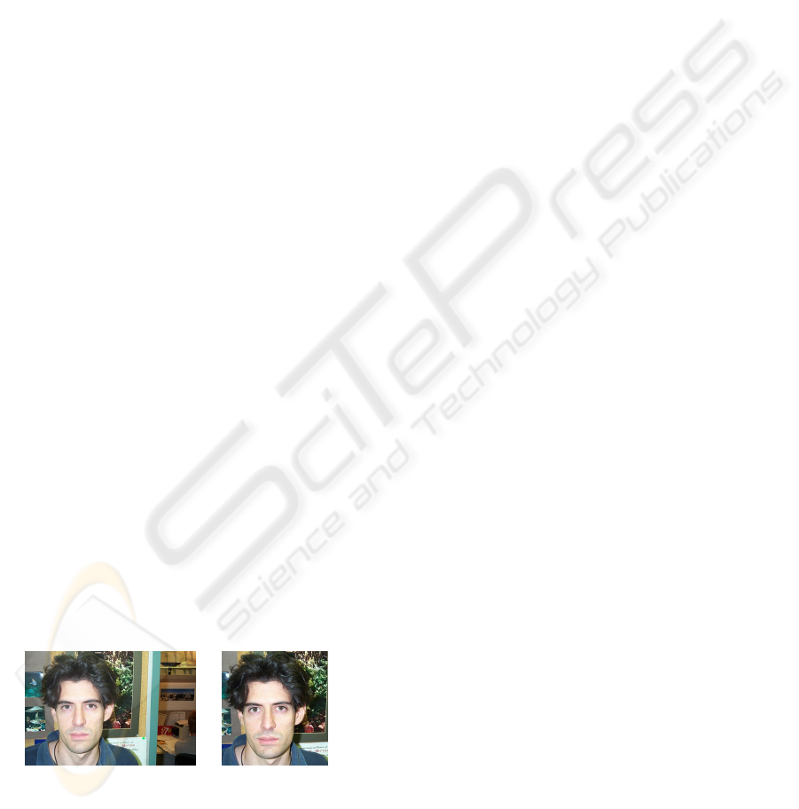
the original image of Figure 1(A) was manually
cropped to get the roughly localized face image
1(B).
(A) (B)
Figure 1: (A) Face image (from CalTech face database),
(B) Roughly localized face image.
Our proposed algorithm is tolerant to some
amount of background, and therefore the preceding
process of face detection need not be ‘perfect’. If
necessary, it may allow an increase in the detected
face extent to ensure that complete face is included.
The following algorithm details the proposed
method.
Algorithm for eye detection:
Input: Roughly localized face image.
Output: Two eyes, eye centers, iris
centers.
// Feature based part
Select potential regions for eyes.
Make pairs of selected regions.
For each pair:
Begin
Perform orientation correction
according to the pair
Test the pair
1) geometrically
2) for distinctive features
3) for symmetry
If all the tests are successful
Store the pair as a potential
region pair (PRP)
If a sufficient number of PRPs are
obtained
Break
End
// Template matching
For each PRP:
Begin
Generate eye LEM template and
perform matching
End
Select the best matched PRP as the
eye pair
Use recursive centroid finding to get
eye centers.
Find iris centers using eye centers.
The terms in bold italics in the above high level
algorithm are key processes which are explained in
the following sub-sections.
3.1 Feature-Based Selection of
Potential Eye Region Pairs (PRPS)
Selection of potential regions for eyes is based on
the following characteristics:
(a) Iris boundary has very high edge strength, and so
it may even appear in an edge map produced
with very high threshold.
(b) Eye regions obtained in an edge map at a very
high threshold, after applying connected
component analysis (see below), are elliptical to
circular, so their eccentricity should be less than
EYE DETECTION USING LINE EDGE MAP TEMPLATE
153
0.85 (for very small area) or 0.95. This is
because when the area is very small, it contains
pixels from iris region only and so it is expected
to be more circular (have less eccentricity), while
larger areas may have shape that is less circular.
Steps involved in selecting regions for eyes:
(1) Scale the localized original face image (m x n) to
a resolution of 200 x 200 pixels.
(2) Obtain an edge map of gray scale intensity image
using a Sobel operator with a very high
threshold, allowing only the strongest 0.1% of
edges in the first iteration. (If the input image is
colored, it is first converted to gray scale.) If a
sufficient number of PRPs is not obtained, then
repeat the process with a smaller threshold.
(3) Perform connected component analysis to find
different connected regions in the image. Pixel
‘i’ is considered connected to all the pixels
which lie in the 11x11 matrix of pixels centered
at ‘i’, and to all the pixels connected to the pixels
lying in the matrix, and so on.
(4) Select regions which have area greater than
lower threshold and eccentricity less than 0.85,
or area greater than upper threshold and
eccentricity less than 0.95. In the current version
of the algorithm, based on the size of normalized
images, the two area thresholds are 3 and 10
respectively.
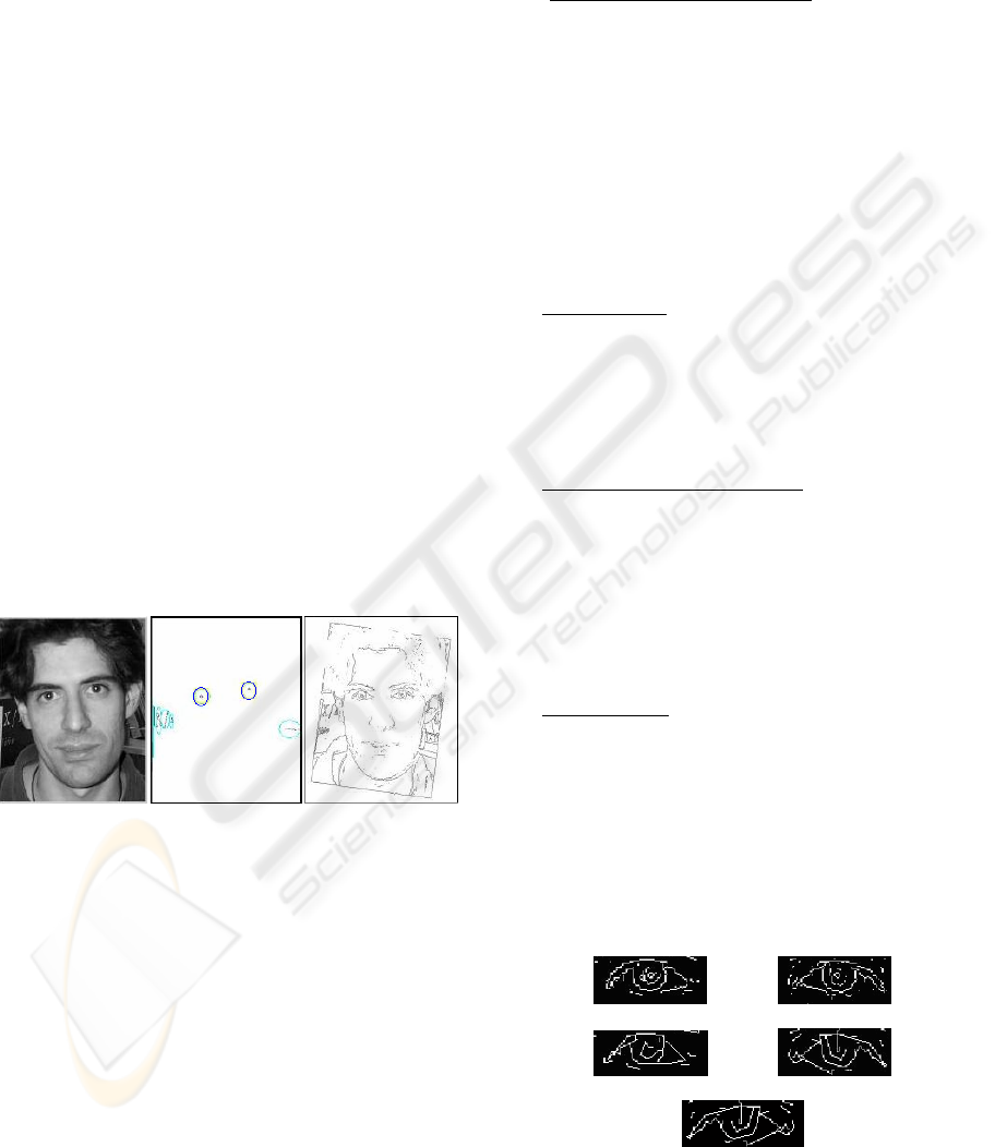
(A) (B) (C)
Figure 2: (A) Input gray scale image from CalTech, (B)
Selected potential regions which are tested in pairs to get
PRPs -- the regions highlighted with two ellipses in the
center show the correct choice for PRP, (C) Result of
orientation correction when the correct pair is chosen.
A gray scale intensity image and potential
regions obtained from its edge map at a high
threshold are shown in Figure 2 (A) and 2 (B). For
better visibility, the image in Figure 2(B) has been
artificially enhanced by inverting it, highlighting the
regions in it, and making a boundary around it.
Image in 2(C) is also inverted for better visibility.
Selecting potential region pairs (PRPs) is based on
the following characteristics:
(a) Using eye positions, other features can be easily
located using the golden ratio (Φ), because
certain key proportions between features of the
human face are based on this ratio
(
http://goldennumber.net/face.htm).
(b) In gray scale intensity image, the area between
the two eyes is brightest in the middle of the
rectangular region between them, and in the edge
map the same area is uniformly dark. Selected
PRPs should have this distinctive feature.
(c) Eyes are symmetric with respect to the
perpendicular bisector of the line joining the two
eyes.
To select the PRPs, we test all possible pairs of the
selected potential regions:
(1) Geometrically
: Test each pair using the golden
ratio and the distance between the centroids of
two regions of the pair, for consistency with face
geometry. If a pair passes this test, orientation
correction is performed (see Figure 2 (C)); once
again, using the golden ratio, non-essential part
of the image is cropped for the next two tests.
(2) For the distinctive features
: Perform vertical
projection of all the pixels in the rectangular
region between the two eyes. Test whether the
global maximum of the projection of gray scale
image and the global minimum of the projection
of the edge map are both in the middle part. For
the projection, we simply convolved an
appropriately selected matrix of all ones with the
rectangular region between the two eyes.
(3) For symmetry
: Compute the similarity between
the LEM of right eye and the LEM of mirror
image of left eye (see Figure 3) by primary line
segment Hausdorff distance (H
pLHD
). Here LEMs
are obtained after applying a cleaning operation
and checking for minimum area of the two eyes
extracted using the pair centroids and the golden
ratio. To pass this test, H
pLHD
should be less than
a threshold, set to an experimentally determined
value of 9 in the present implementation.
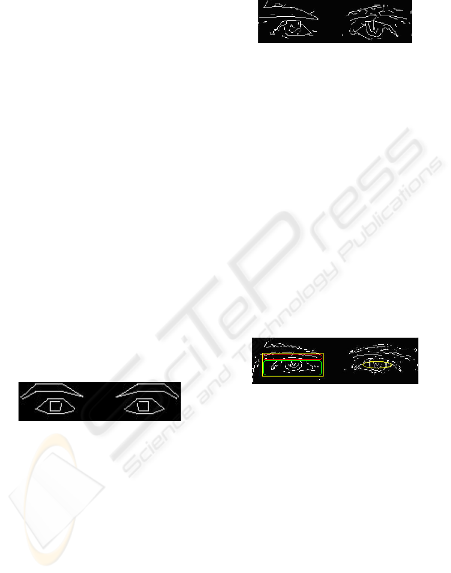
(A) (B)
(C) (D)
(E)
Figure 3: (A) and (B) are extracted edge maps of both the
eyes, (C) and (D) are LEMs of both the eyes and (E) is
LEM of mirror image of the left eye.
VISAPP 2008 - International Conference on Computer Vision Theory and Applications
154
Note that PRP is an edge map of potential pair of
regions as shown in Figure 3; it is not to be mistaken
with the eye LEM (shown in Figure 5) which is the
result of applying polygonal line fitting by dynamic
two strip algorithm (
Leung and Yang, 1990) on PRP.
3.2 Template-Matching
Selected PRPs may not always correspond to eye-
pairs, because:
(a) The geometrical test serves only to filter out
weak pairs, and therefore it can let in an
erroneous pair.
(b) It has been observed during implementation that
the test for distinctive features is also passed by a
dark pair of nostrils (mostly in upright faces) and
an eye. Sometimes this test also fails due to a
mark on the face, an unusual lighting condition,
shiny hair, etc.
(c) The test for symmetry does not usually fail due
to unusual lighting, shiny hair, etc. But it may
fail due to the symmetric inner or outer corners
of the eyes, eyelids, regions below eyelids, and
eyebrows which can escape all the three tests.
Therefore template-matching is applied here to
select a PRP which is surely an eye region. The
template used here is the LEM of an artificial pair of
eyes (frontal face) including eyebrows. It is
constructed according to the distance between the
two centroids of the PRP with which it is to be
matched, based on the golden ratio Φ. Such an
artificial eye LEM is shown in Figure 4.
Figure 4: Artificial Eye LEM.
For each PRP:
(a) Eye region including eyebrows is extracted
using the golden ratio by considering the two
centroids as the eye centers.
(b) LEM of this eyes region is obtained (an
example is shown in Figure 5).
(c) Artificial eye LEM template is generated.
(d) Matching is done using H
pLHD
.
(e) The best matched PRP is selected.
Though the template is designed for a fully
frontal face, it does serve its purpose because the
best match for the eye LEM template cannot be any
non-eye region, unless there is a pose variation of
greater than 45 degrees.
Figure 5: LEM of extracted eye region.
3.3 Finding Eye and Iris Centers
After eye LEM template matching, most of the time
the centroid of each selected region lies in the region
indicated by the ellipse shown on the right in Figure
6. It is not always very accurate, but we can almost
be assured of it lying in the region enclosed by the
outer rectangle, shown on the left in Figure 6. If the
centroid lies in the lower inner rectangle, we do
eventually get to the correct result after the
processing explained next. But if it lies in the upper
inner rectangle, then the algorithm may not yield
accurate results in that instance.
Steps for finding eye centers:
(1) Locate left and right eye regions from the
selected PRP, using the golden ratio.
(2) Recursive centroid finding: Find the two
centroids of the two regions, and again locate
eye regions using these new centroids.
Continue until convergence for both the eyes,
or for a maximum of 10 iterations.
Figure 6: Different regions in edge map of extracted eye
region.
The process of finding iris centers is based on the
fact that, in the approximately localized eye region,
the darkest part is the iris region.
Steps for finding iris centers, given eye centers:
(1) Using the eye centers we locate and extract the
left and right eye regions (Figure 7(A)) from the
original image.
(2) Obtain a binary image with value 1 for the darker
parts of the region and zero for the rest (Figure 7
(B), left part).
(3) Take the largest two areas (Figure 7(B), right
part) and find their centers as the two iris centers.
Figure 8 shows the localized faces (input images
from Caltech) according to the detected eye
locations (highlighted with a cross). Eye positions
EYE DETECTION USING LINE EDGE MAP TEMPLATE
155

(A)
(B)
Figure 7 (A) Extracted eye regions from original image,
(B) Left part: binary image showing darker parts of the
eye region; Right part: binary image showing the largest
two areas among darker parts.
detected till LEM template matching are shown in
Figure 8(A), which are further refined to get the two
eye centers (Figure 8(B)) and iris centers (Figure
8(C)).
We can clearly see that the centers of eyes are
better for exact face localization than those of iris.
This is because in the cases (such as those shown in
Figure 8) where a person is looking sideways, the
irises are not in the center and the face which is
localized using the golden ratio is not exact.
Therefore, for normalization before face recognition,
eye centers should be used, whereas for iris contour
detection or possible tracking, iris centers can of
course be used.
(A) (B) (C)
Figure 8: (A) Eye detection till eye LEM template
matching, (B) Eyes centers detection, (C) Irises centers
detection.
4 EXPERIMENTAL RESULTS
In this section, we present results of our algorithm.
For testing we have used images from CalTech and
Georgia Tech face databases. CalTech face database
contains 450 face images of 27 individuals with
different expressions, lighting conditions and
background. Georgia Tech face database contains 15
images each of 50 individuals, with variation in
pose, expression and lighting conditions. In our test
set we included 120 images from CalTech database
and 120 from Georgia Tech database, chosen
randomly from the faces without spectacles.
Normalized error is measured by the quotient
between the localization error and the ground truth
intraocular distance (
Lizuo Jin, Xiaohui Yuan, Shinichi
Satoh, Jiuxian Li, Liangzheng Xia, 2006). Here the
maximum of the localization errors for right and left
eyes is taken as the localization error. For eye center
detection, 91.67% of the outputs from 240 images
have normalized error less than 0.1, and for iris
center detection, the result is 95.42% for the same
normalized error. The results for normalized error of
0.1 are shown in table I.
Table 1: Results of Eye Detection.
Database Detection type Result
Eye center 92.50%
Cal Tech
Iris center 96.67%
Eye center 90.83%
Georgia
Tech
Iris center 94.12%
Figure 9 shows a few examples of detection
results from CalTech database for eye center (upper
part) and iris center (lower part). Some eye detection
results from Georgia Tech are shown in Figure 10.
All faces shown in these results are localized
according to the detected eye locations. It is seen
that the algorithm gives excellent eye detection and
face localization results on both the face databases.
Figure 9: Examples of eye center and iris center detection
in the images from CalTech face database.
Figure 10: Examples of eye detection in the images from
Georgia Tech face database.
VISAPP 2008 - International Conference on Computer Vision Theory and Applications
156

5 CONCLUSIONS
An eye detection algorithm can prove to be
extremely useful in the pre-processing phases of face
recognition systems. A robust eye detection
algorithm has been developed, which combines the
efficiency of feature-based approaches with the
accuracy of template-based approaches. The
algorithm first finds region pairs which can
potentially be eye pairs using feature-based methods,
and then employs template-matching to select the
best pair. The idea is introduced of applying the line
edge map (LEM), a face feature representation, for
symmetry measurement and template matching,
making use of eye and eye region LEMs.
Experimental results confirm the correctness and
robustness of the algorithm to pose, expression and
illumination variations.
Recently a comparison of three eye detectors has
been presented by Everingham and Zisserman
(Everingham and Zisserman, 2006). The approach of
our proposed method is different from these three, in
the sense that no learning is required for the
classification of eye portion and non-eye portion.
However, a comparison of the relative performance
of these methods needs to be carried out.
REFERENCES
Ming Hsuan Yang, Kriegman. D. J, Ahuja N., Jan 2002.
Detecting faces in images: a survey. In IEEE
Transactions on Pattern Analysis and Machine
Intelligence, vol. 24, no.1, pp 34-58.
Brunelli F. R., Poggio T., 1993. Face Recognition: feature
versus templates. In IEEE Transactions on Pattern
Analysis and Machine Intelligence, 15 (10), 1042-
1052.
Huang J., Wechsler H., 2000. Visual routines for eye
location using learning and evolution. In IEEE
Transactions on Evolutionary Computation, 4(1), pp.
73-82.
Tian Y., Kanade T., Cohn J.F, 2000. Dual-state parametric
eye tracking. In Proc. 4
th
IEEE International.
Conference on Automatic Face and Gesture
Recognition.
Kwato S., Ohya J., 2000. Real-time detection of nodding
and head shaking by directly detecting and tracking
the between-eyes. In Proc. 4
th
IEEE International.
Conference on Automatic Face and Gesture
Recognition, pp. 40-45.
Yuille A. L., Hallinan P. W., Cohen D. S., 1992. Feature
extraction from faces using deformable templates. In
International Journal of Computer Vision, 8(2), pp.
99-111.
Vezhnevets V., Degtiareva A., September 2003. Robust
and Accurate Eye Contour Extraction. In Proc.
Graphicon, Moscow Russia, pp. 81-84.
Pentland A., Moghaddam B., Starner T., 1994. View-
based and modular eigenfaces for face recognition. In
Proc. IEEE Conference on Computer Vision and
Pattern Recognition (CVPR’94), Seattle, WA.
Kun Peng, Liming Chen, Su Ruan, Georgy Kukharev, Oct
2005. A robust algorithm for eye detection on gray
intensity face without spectacles. In JCS&T, vol. 5, no.
3, 127-132.
Gao Y., Leung M.K.H., June 2002. Face recognition using
line edge map. In IEEE Transactions on Pattern
Analysis and Machine Intelligence, vol. 24, no. 6, June
2002.
Leung M.K.H. and Yang Y.H., 1990. Dynamic two-strip
algorithm in curve fitting. In Pattern Recognition, vol.
23, pp 69-79.
Everingham M., Zisserman A., 2006. Regression and
classification approaches to eye localization in face
images, In proc. of Internation conference on Face and
Gesture.
California Tech Face Database, www.vision.caltech.edu/
Image Datasets/faces/faces.tar.
http://goldennumber.net/face.htm.
Lizuo Jin, Xiaohui Yuan, Shinichi Satoh, Jiuxian Li,
Liangzheng Xia, 2006. A hybrid classifier for precise
and robust eye detection. In 18th International
Conference on Pattern Recognition (ICPR'06), pp.
731-735.
Georgia Tech Face Database
http://www.anefian.com/face_reco.htm.
EYE DETECTION USING LINE EDGE MAP TEMPLATE
157
