A DYNAMIC MODEL OF A BUOYANCY SYSTEM IN A WAVE
ENERGY POWER PLANT
Tom S. Pedersen and Kirsten M. Nielsen
Department of Automation and Control
Aalborg University, Fr. Bajersvej 7, Aalborg, Denmark
Keywords: Dynamic model, wave energy, simulation, buoyancy control, verification, renewable energy.
Abstract: A nonlinear dynamic model of the buoyancy system in a wave energy power plant is presented. The plant
(“Wave Dragon”) is a floating device using the potential energy in overtopping waves to produce power. A
water reservoir is placed on top of the WD, and hydro turbines lead the water to the sea producing electrical
power. Through air chambers it is possible to control the level, the trim and the heel of the WD. It is
important to control the level (and trim, heel) of the WD in order to maximize the power production in
proportion to the wave height, here the amount of overtopping water and the amount of potential energy is
conflicting. Five separate air chambers, all open to the sea, makes the device float. The pressures in the air
chambers may be individually controlled by an air fan through an array of valves. In order to make a model-
based control system, this paper presents a model describing the dynamics from the air inlet to the level,
trim and heel. The model is derived from first principles and is characterized by physical parameters.
Results from validation of the model against plant data are presented.
1 INTRODUCTION
Renewable energy is an important issue due to the
global warming problem and utilisation of wave
power is one of the energy resources to be exploited.
The wave power system “Wave Dragon”, on
which this paper focuses, was invented by Erik Friis
Madsen, Löwenmark and tested at Aalborg
University and University of Cork. An EU based
European consortium has been involved in the
construction and implementation of a 1:4 scaled test
site - 57x27 m wide and with a weight of 237
tonnes- which is placed in Nissum Bredning in
Denmark. Large numbers of tests have been carried
out during a two years operating period. One goal
for energy production improvement is a better
control of the Wave Dragon buoyancy.
Wave Dragon (WD) is an offshore wave energy
converter of the overtopping type, a description is
found in (Kofoed, 2006) and (W.D.Aps, 2006). The
main structure consists of a ramp where the waves
are overtopping and led to a reservoir (basin). Two
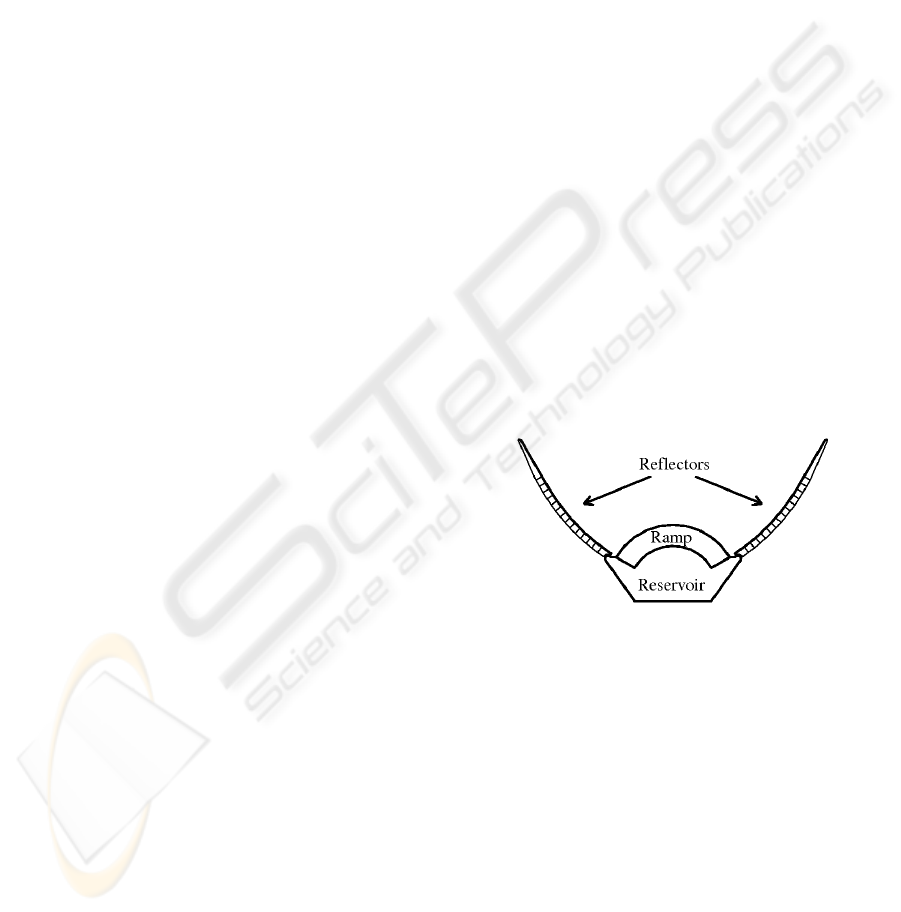
reflectors are focusing the waves towards the ramp
as seen on figure 1. WD is fastened to an anchor
making it possible to turn the ramp towards the
dominant wave direction.
Figure 1: Main components of the Wave Dragon (Kofoed,
2006).
The WD use the potential energy of the waves,
meaning that for a given wave type there exist an
optimal level of the reservoir. As shown on figure 2
the reservoir water is led through a turbine.
The WD floats on open air chambers used to
adjust the floating level. Control of the floating level
is a part of optimizing the overtopping and a
dynamic model for a model-based control system is
the topic of this paper. It should be noted that the
wave conditions are measured online and may be
used as reference to the level control system.
First the wave dragon buoyancy system is
presented. A dynamic model of the air supply system
controlling the pressure in the air chambers is set up.
13
S. Pedersen T. and M. Nielsen K. (2008).
A DYNAMIC MODEL OF A BUOYANCY SYSTEM IN A WAVE ENERGY POWER PLANT.
In Proceedings of the Fifth International Conference on Informatics in Control, Automation and Robotics - SPSMC, pages 13-17
DOI: 10.5220/0001479200130017
Copyright
c
SciTePress
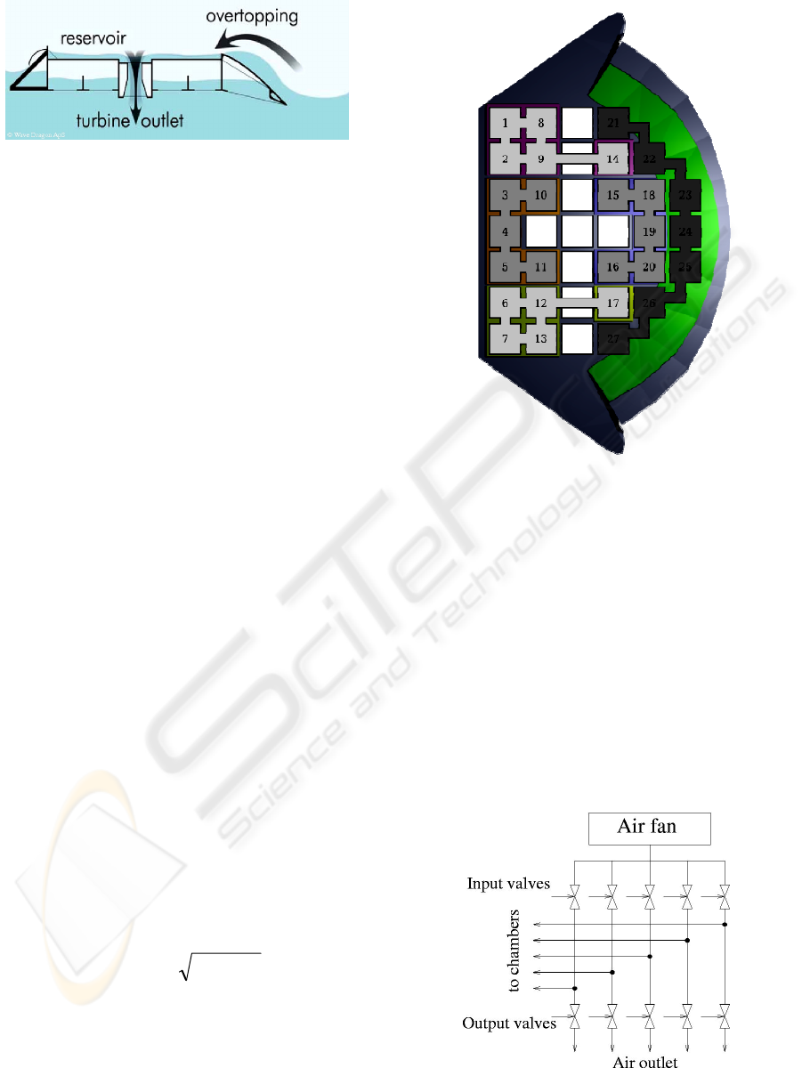
Figure 2: The basic principle of WD showing waves
loading the reservoir via the ramp. (Kofoed, 2006).
The model parameters have been adjusted to the test
site Wave Dragon. Finally the buoyancy model is
verified by comparing simulation results and
measurements from the test site Wave Dragon.
2 DYNAMIC MODEL OF THE
BUOYANCY SYSTEM
The buoyancy system consists of five air chambers
all open to the water surface. The five chambers are
shown on figure 3 (21,22,23,24,25,26,27),
(15,16,18,19,20), (3,4,5,10,11), (1,2,8,9,14) and
(6,7,12,13,17). Furthermore 9 small chambers
contain a constant amount of air.
The air pressures in the chambers are controlled
by an air supply system using an on/off driven air
fan and input/output valves to each chamber. The
valves are operated as on/off valves and only one
valve is allowed to be active at the time in order to
prevent pressure equalizing in the chambers. A
PWM scheme is in (Andersen, 2007) proposed to
handle this problem. The air supply system model
consist of two parts, one describing air inlet to the
chamber and one describing air flow out of the
chamber. In both models tube pressure drops are
ignored. The inlet air mass flow, m
ai,
is given by
pbacpaai
KppKm +−−= )(
which is an approximation to the fan characteristic.
p
c
is the chamber pressure, p
a
is the inlet pressure to
the fan (atmospheric pressure) and the two
constants K
pa
, K
pb
are from the fan data sheet.
Air outlet mass flow, m
ao,
is given by the
Bernoulli equation:
acvoao
ppKm −=
where the constant K
vo
depend on the outlet tube
dimension and the air density.
Each input/output valve pair is controlled by a signal
u, where u=1 allows an airflow into the chamber,
u=0 closes both valves and u=-1 open the outlet
valve. This gives the air mass flow equation:
Figure 3: The air chambers in the Wave Dragon.
)()(
21
ugmugmm
aoaia
−
=
(1)
where
⎩
⎨
⎧
<
≥
=
10
11
)(
1
uif
uif
ug
⎩
⎨
⎧
−>
−≤
=
10
11
)(
2
uif
uif
ug
Eq. (1) describes the air mass flow to the chamber
and is valid when only one chamber is operated at a
time.
Figure 4: Fan/valve system.
ICINCO 2008 - International Conference on Informatics in Control, Automation and Robotics
14
3 ONE CHAMBER DYNAMIC
MODEL
This section outlines the dynamic describing
equations for a single chamber. The equations
assumes that the air density is constant (variations
could be included using the ideal gas equation), the
chamber is only moving along a vertical axis
perpendicular to the water surface, the cross section
area is constant along this axis and there is only one
rigid moving body. The model then consists of a
mass balance equation describing the air in the
chamber and a Newton equation describing the
motion of the chamber.
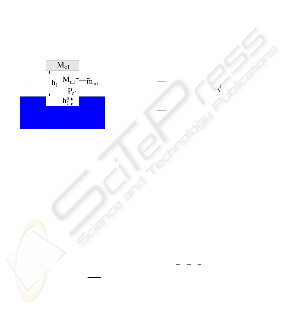
Figure 5: One chamber model variables.
The mass balance equation for the chamber is
dt
hhd
Am
dt
dM
aa
a
)(
11
11
1
+
==
Δ
ρ
(2)
where M
a1
is the air mass in the chamber, m
a1
is the
mass flow to the chamber, A
1
is the cross section
area, ρ
a
is the air density,
Δ
1
h is the distance from
the chamber water surface to the ambient water
surface and h
1
is the distance from the ambient water
surface to the top of the chamber.
The pressure force from the chamber is assumed
to equal the buoyancy force. This implies that the
acceleration of the water volume in the chamber is
small.
111111
1
c
w
cw
p
g
hApgAh
ρ
ρ
=⇒=
ΔΔ
(3)
where ρ
w
is the water density. Insertion of Eq. (2) in
Eq. (3) gives
dt
dh
gm
A
g
dt
dp
wa
a
wc
1
1
1
1
ρ
ρ
ρ
−=
(4)
The other main equation for describing the
dynamics of the chamber is Newton’s 2’th law used
on the free body with the mass M
c1.
Pressure forces,
gravity and a friction force proportional with the
chamber velocity is assumed to act on the body.
dt
dh
KgMApp
dt
hd
M
fcacc
1
1111
2
1
2
1
)( −−−=
(5)
In order to use an ODE-solver to simulate the one
chamber model, the three states
11 c
px =
,
12
hx
=
and
dt
dh
x
1
3
=
may be selected resulting in the
differential equation system
⎥
⎥
⎥
⎥
⎥
⎥
⎥
⎥
⎥
⎦
⎤
⎢
⎢
⎢
⎢
⎢
⎢
⎢
⎢
⎢
⎣
⎡
−−−
−−
+−−+−
=
⎥
⎥
⎥
⎥
⎥
⎥
⎦
⎤
⎢
⎢
⎢
⎢
⎢
⎢
⎣
⎡
31111
3
211
1
1
3
3
2
1
)(
))()()
)(((
xKgMApx
x
ugpxKugK
pxK
A
g
gx
dt
dx
dt
dx
dt
dx
fca
avopb
apa
a
w
w
ρ
ρ
ρ
(6)
4 FIVE-CHAMBER DYNAMIC
MODEL
In this section a 5 chamber dynamic model is
described. Although the WD has a complex
geometry the model assumes that each of the five
chambers may be regarded as a control volume with
position independent internal variables and that each
chambers pressure force actuate the WD bode in a
single point. The model consist of 8 differential
equations, 5 equations describing the pressures in
the five chambers derived from mass balance
equations, and 3 equations describing height, trim
and heel derived from Newton’s law.
The five chambers are placed in a “wave dragon”
coordinate system {WD} with the
coordinates
),,(
n
n
n
zyx
. An inertial coordinate
system {I} is placed in the water level as shown on
the figure. The states in the model are the five
chamber pressures (p
c1
, p
c2
, p
c3
, p
c4
, p
c5
), the trim
angle (θ), the heel angle (γ) and the level (h) of the
wave dragon.
A DYNAMIC MODEL OF A BUOYANCY SYSTEM IN A WAVE ENERGY POWER PLANT
15

Figure 6: Wave dragon coordinate systems.
The mass balance for the n’th chamber is
dt
dh
gm
A
g
dt
dp
n
wan
an
wcn
ρ
ρ
ρ
−=
h
n
is the height in the chamber and not a model state.
Using a rotation matrix
),,(
αγθ
R
I
WD
(see (Craig,
1989)), h
n
and the states are related through
hz
yxh
n
n
n
n
+
++−=
)cos()cos(
)sin()cos()sin(
θγ
θγγ
The time derivative of h
n
is a tedious equation but
using the approximations cos(θ)= 1, cos(γ) = 1,
sin(θ) = θ, sin(γ)= γ assuming small heal and trim
angles (all z
n
’s are 0) gives the simple relation
dt
dh
dt
d
y
dt
d
x
dt
dh
n
n
n
++=
θγ
which inserted gives
)(
dt
dh
dt
d
y
dt
d
xgm
A
g
dt
dp
n
n
wan
an
wcn
++−=
θλ
ρ
ρ
ρ
(7)
Newton’s 2’th law for the translational system is
2
2
5
1
)(
1
dt
hd
g
Ap
M
dt
dh
K
ApgM
h
KpA
ww
wdf
wwwdflh
n
cnn
+=
−−−+
∑
=
(8)
where the sum is chamber pressure forces acting on
the wave dragon body. The second term is the forces
from the air chambers containing a constant air mass
(see figure 3). In the model these are approximated
with two chambers. They may be modelled using the
mass balance Eq. (4) but in order to keep the model
order low they are modelled using a static balance.
K
flh
may be found using the ideal gas law and the
geometrics of the chambers. M
wd
is the total mass of
the wave dragon. The term p
w
A
w
represents the force
from the water reservoir on top the Wave Dragon. It
may be noted that the pressure p
w
is an input to the
model.
The rotational trim equation is
2
2
2
5
1
dt
d
J
dt
d
K
h
K
ypA
fl
n
n
cnn
θθ
θ
θθ
θ
=−−
∑
=
(9)
where the sum is the torque from the chambers. The
second term is the torque from the constant air mass
chambers modelled as two symmetrical chambers. It
should be noted that K
flh
as well as K
flθ
are very
dependent on the total air mass in the chambers. The
moment of inertia is calculated as a constant
although it depends on the water level in a very
complex manner. In the simulation a situation with
low water level has been used.
The heel equation is
2
2
5
1
dt
d
J
dt
d
KKypA
fl
n
n
cnn
γγ
γ
γγγ
=−−
∑
=
(10)
This linear second order equation captures the
gross behaviour of the heel dynamics.
The total model now consist of eleven equations,
equation (7) used 5 times for the five chambers
giving the five states
11 c
px = ,
22 c
px
=
,
33 c
px
=
,
44 c
px
=
,
55 c
px = , equation (8)
with the states
hx
=
6
,
d
t
dh
x =
7
and the equation
7
6
x
dt
dx
=
gives 2 equations, equation (9) with the
states
θ
=
8
x
,
dt
d
x
θ
=
9
and the equation
9
8
x
dt
dx
=
gives 2 equations, and finally equation (10) with the
states
γ
=
10
x
,
dt
d
x
γ
=
11
and the equation
11
10
x
d
t
dx
=
gives 2 equations.
Inserting the states (
1121
,...,, xxx ) gives eleven
nonlinear first order equations. The equations are
solved using an ODE-solver.
ICINCO 2008 - International Conference on Informatics in Control, Automation and Robotics
16
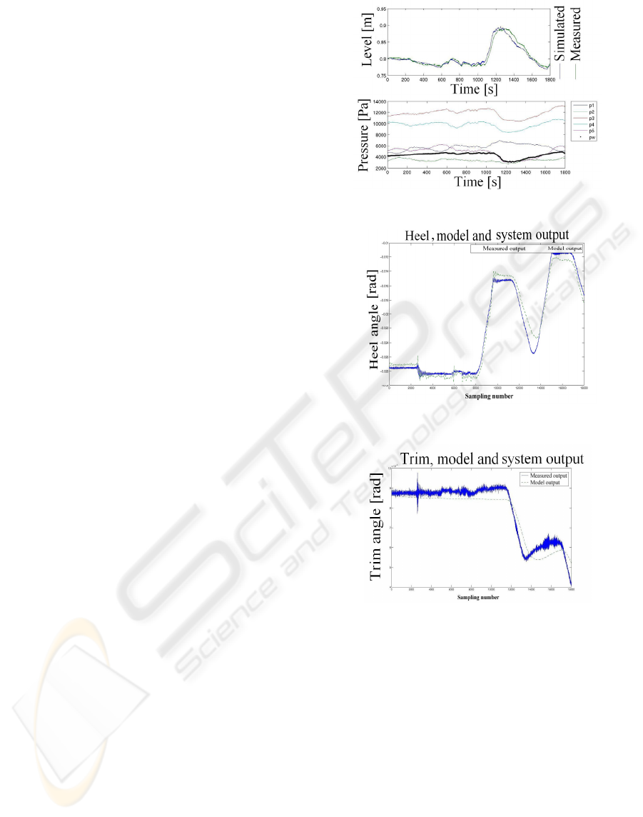
5 SIMULATION
The model is tested using measured data from the
wave dragon. The inputs to the model are the
chamber pressures as well as the water level in the
dragon represented by the pressure measurement p
w
.
The reason for not using the valve signals is that
these were not recorded in the data acquisition
equipment. As seen there is a good agreement
between level in the model and the experimental
data. (The agreements are found on the
measurements from the same day. Measurements on
different days are based on different initial pressures
causing identification of slightly different model
parameters) (This is also found on data measured
on the same day.) Because the pressures in the
constant air chambers are not measured these have
been estimated from steady state observations.
The variations on the heel and trim angles are small.
As seen on the figures the behaviour is captures by
the model. All the data were recording prior to this
project and not prepared for this study, unfortunately
the WD run severely aground during the project
meaning that controlled input signal could not be
tested. Regardless of this the model performed well
on the recorded data.
6 CONCLUSIONS
A nonlinear physical model with a complexity that is
suitable for model based control has been presented.
The model is partly based on physical parameters for
the Wave Dragon and may be scaled to a future larger
version. The model has four main equations, one
describing the state of the air in a chamber, and three
accounting for the level, trim and heel motion of the
WD. The model has been validated against measured
WD data, where it captures the gross behaviour of the
Wave Dragon. In particular it describes the response of
the level very well. The model does, however, have one
serious deficiency because it does not capture the
distribution and movement of water in the water
reservoir. A comprehensive study of this is outside the
scope of this paper.
Figure 7: Level simulated and measured.
Figure 8: Heel simulated and measured (Andersen, 2007).
Figure 9: Trim simulated and measured (Andersen, 2007).
REFERENCES
Andersen, J., Hundsdahl, M.Y., Jensen, P.K.,
Vilbergsson, K.S., Vidarsson, O., Skagestad, R., 2007,
Control of Wave Dragon Buoyancy, master thesis,
Aalborg University.
Craig, J.J., 1989, Introduction to Robotics,mechanics and
control, ISBN 0-201-09528-9.
Kofoed, J.P., Frigaard, P. Friis-Madsen, E. Sørensen, H.C.
2006, Prototype testing of the wave energy converter
wave dragon, Renewable Energy 31 181-189.
W.D. Aps , 2006, Wave Dragon – principles,
http://www.wavedragon.net
A DYNAMIC MODEL OF A BUOYANCY SYSTEM IN A WAVE ENERGY POWER PLANT
17
