
CALIBRATION ASPECTS OF MULTIPLE LINE-SCAN VISION
SYSTEM APPLICATION FOR PLANAR OBJECTS INSPECTION
Andrei Hossu and Daniela Hossu
University Politehnica of Bucharest, Faculty of Control and Computers
Dept. of Automatics and Industrial Informatics, 313 Spl. Independentei, sector 6, RO-77206, Bucharest, Romania
Keywords: Industrial Vision System, Line-Scan Camera, Dual-Camera Vision System, and Moving Scene in Robotic
Automation.
Abstract: The System Set-up Time it is one of the characteristics of an Industrial Vision System, besides the accuracy
performances and response time. Minimizing the set-up time while keeping the performances in accuracy
and in response time is one of the goals of any advanced Vision System. Starting from the purpose and the
required performances of the proposed Industrial Vision System, in the paper is presented a calibration
method developed for a multiple line-scan camera Vision System (in particular for a dual line-scan camera
system). The calibration method presented is based on analyzing the image of a calibration tool exposed to
the Vision System. There are presented the type of dimensional distortions identified from the experimental
results. The second part of the paper presents the calibration method. The Industrial Vision System
described in the paper is designed for silhouette inspection of planar objects located on a moving scene
(transport conveyor), in a robotic handling application (it is a pure 2D Vision System, the volumetric
characteristics of the analyzed objects being not relevant for the application). However the height of the
object is varying in time (from one set of objects to another). Due to the fact the distance between the
cameras and the objects is changing, the measuring results are affected. The proposed calibration method
allows the Vision System to self adjust the calibration parameters for a known change in height of the
objects, without affecting the accuracy system performances. In the final section of the paper are presented
some practical aspects of the proposed calibration method, and the balance between the off-line and the on-
line required computational efforts from the Vision System.
1 MULTI LINE-SCAN CAMERA
VISION SYSTEMS
CHARACTERISTICS
The class of the Artificial Vision Systems dedicated
for analyzing objects located on a moving scenes
(conveyor) presents some specific characteristics
relative to the Artificial Vision Systems dedicated
for static scenes. These characteristics are identified
also on the Image Calibration Process (Borangiu, et
al., 1994)., (
Haralick and Shapiro, 1992).
Figure 1 presents the model of the image
obtained from a dual line-scan camera Vision
System.
For this class of the Artificial Vision Systems we
could identify as relevant for the calibration process
the following characteristics:
- The system is using line-scan cameras for
the image acquisition.
- The system is a dual-camera.
- The obtained image has significant
distortions on (and only on) the image sensors
direction.
- There is an overlapped image area
between the two cameras. The end of the
acquisition line of the 1
st
camera is overlapping
the beginning of the acquisition line of the 2
nd
camera. This overlapping area is significant in
dimension and is a constant parameter resulted
during the artificial vision system installation
process.
- There is a lengthwise conveyor distance
between the acquisition lines of the two
cameras. This distance is also a constant
parameter and its value is fixed during the
system installation process.
36
Hossu A. and Hossu D. (2008).
CALIBRATION ASPECTS OF MULTIPLE LINE-SCAN VISION SYSTEM APPLICATION FOR PLANAR OBJECTS INSPECTION.
In Proceedings of the Fifth International Conference on Informatics in Control, Automation and Robotics - RA, pages 36-40
DOI: 10.5220/0001480300360040
Copyright
c
SciTePress

2 THE PATTERN BASED
CALIBRATION TOOL
For the calibration process we adopted the method
of using a Pattern based Calibration Tool.
This Pattern based Calibration Tool represent a set
of blobs with a priori known dimensions and
locations for the real world (millimeters and not
image pixels) (Croicu, et al., 1998).
The outcome of using this type of calibration
technique was to obtain the following:
- Estimation with the highest accuracy of the
scene model parameters on the distortions
direction
- Estimation of the size of the overlapped image
area for both cameras
- The parallelism of the two acquisition lines if
obtain during the installation process, using the
support of the Calibration Tool
- The accuracy of installing the cameras in such a
way to obtain the perpendicularity of the
acquisition lines on the moving direction of the
scene (of the conveyor).
- Obtain a high accuracy on the distance
lengthwise the conveyor of the acquisition lines.
The shape and the dimensions of the pattern
adopted for the Calibration Tool force this
characteristic.
3 CALIBRATION TOOL
DESCRIPTION
In Figure 2 it is presented the pattern adopted for the
Calibration Tool used for the dual line-scan camera
Vision System (the dimensions are presented in
millimeters) (Croicu, et al., 1998)., (Hossu, et al.,
1998).
The characteristics of the adopted Pattern:
- The pattern contains dark blebs (marks)
placed on a bright background (with a high level
of light intensity for the image)
- The pattern is symmetrical on the vertical
direction (lengthwise the conveyor). The two
cameras have the acquisition lines parallel one
each other but located on different position on
the conveyor (due to the lighting system
adopted – built from two fluorescent tubes used
for obtaining the image from the reflection on
the object surface). 1st Camera will have the
acquisition line located on the top edge of the
lower section of the pattern, and the 2nd
Camera will locate its acquisition line on the
bottom edge of the upper section of the pattern.
- The pattern is partially homogenous on the
horizontal axis (the direction crosswise the
conveyor, the direction of the distortions)
- The pattern contains a characteristic of a small
difference (1 mm.) between the even and the
odd marks. This will force the installation
process to be very accurate in obtaining
the parallelism of the acquisition lines of the
cameras and also the perpendicularity on the
conveyor direction.
Figure 1: The image obtained from a dual line-scan camera Vision System.
CALIBRATION ASPECTS OF MULTIPLE LINE-SCAN VISION SYSTEM APPLICATION FOR PLANAR OBJECTS
INSPECTION
37

4 EXPERIMENTAL RESULTS OF
THE CALIBRATION PROCESS
In Figure 3 are presented the results obtained from
the Calibration process performed on the 1
st
Camera.
The Excel Cell used as support for representing
the results of the Calibration on the 1
st
Camera
contains the following:
- The 1
st
column (called Mark) contains the
number of the corresponding Mark existing in
the pattern
- The 2
nd
column (called Calib. Cam)
contains the values of the coordinates of the
marks on the Calibration Tool.
These values are obtained from the “real
world” from direct measuring of the Pattern
applied on the Calibration Tool (represented in
millimeters).
- The 4
th
column (called Pixel(x)) represents
the coordinates of the existing Marks on the
image. These coordinates are represented in
pixel number.
- For both cameras we chose a Polynomial Trend
of order 3 for the approximation of the
conversion function of the image coordinates
values (pixels) into the conveyor coordinates
values (millimeters). Using this type of trend the
calibration method will provide results with a
maximum approximation error inside the
accuracy requirements of the particular Vision
System
- On the top and right side of the Excel Cell (the
first two rows and the last four columns) are
stored the parameters of the 3
rd
Order
Polynomial estimated as trend.
- The last column (called Estimated (y)) contains
the estimated of the marks coordinates values
(on the conveyor), obtained from applying the
Polynomial trend of order 3.
- In the bottom right side of the Excel Cell is
presented the graphical chart of the trend of the
coordinates values of the marks on the conveyor
related to the pixel coordinates.
Figure 2: The pattern of the Calibration Tool used for the dual line-scan camera Vision System.
LL1 H H1 H2 alfa a1 b1 c1 d1
4636 1408 2592 17 31 3.01984E-03 1.448567E-09 -9.128585E-06 0.5088785 338.9459
Mark Calib Cam1 Real Cam1 Pixel (x) Estimated (y)
1 436 429.08037 175 427.7278
2 535.5 529.18545 380 531.0810
3 635 629.31390 576 629.3081
4 734.5 729.46574 777 729.5128
5 834 829.64098 979 829.7479
6 933.5 929.83962 1181 929.5853
7 1036 1033.08381 1390 1032.5400
8 1135.5 1133.32999 1595 1133.2616
9 1235 1233.59960 1799 1233.3085
10 1334.5 1333.89265 2004 1333.7361
11 1434.5 1434.71331 2210 1434.6181
12 1534 1535.05337 2415 1535.0504
13 1633.5 1635.41690 2621 1636.0883
14 1733 1735.80390 2825 1736.3342
15 1832.5 1836.21437 3028 1836.3487
16 1932 1936.64834 3231 1936.6953
17 2036.5 2042.15453 3443 2041.9242
18 2136 2142.63667 3644 2142.1760
19 2235.5 2243.14232 3844 2242.4668
20 2335 2343.67150 4046 2344.3760
Camera 1
y = 1.44857E-09x
3
- 9.12858E-06x
2
+ 5.08879E-01x +
3.38946E+02
0
500
1000
1500
2000
2500
0 500 1000 1500 2000 2500 3000 3500 4000
Pixel
mm
Figure 3: Experimental results of the calibration process on the 1
st
camera.
ICINCO 2008 - International Conference on Informatics in Control, Automation and Robotics
38
Pixe l Width [m m ]
0.485
0.490
0.495
0.500
0.505
0.510
400 900 1400 1900 2400 2900 3400 3900 4400
mm
mm / pixel
Figure 4: The distortions estimated on the acquisition lines direction.
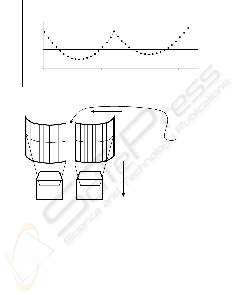
Figure 5: Using the calibration results for a dual line-scan camera system.
In the figure we are using the following notations:
- x coordinate value in image – (pixels)
- y coordinate value on the objects scene (on
conveyor) – (mm)
-
11
2
1
3
1
dxcxbxay +++= for the 1
st
Camera and
-
22
2
2
3
2
dxcxbxay +++= for the
2
nd
Camera
In Figure 4 is presented the graphical chart of the
evolution of the distortions estimated on the
acquisition lines direction. The two cameras are
covering around 4 meters wide view. The figure
represents the behavior of the two acquisition
cameras: in the are from 400 mm to 2250 mm it is
represented the behavior of the 1
st
camera and in the
area from 2250 mm to 4400 mm it is represented the
behavior of the 2
nd
camera.
We can notice the distortions are effecting the
pixel width of the image form 0.49 mm/pixel to
0.507 mm/pixel.
Ignoring this variation of the pixel width along
the image acquisition line, would lead to
accumulation of very high errors in some areas of
the image, due to the fact the amount of pixels
contained in an acquisition line is high (8096).
5 CONCLUSIONS
The most important thing obtained from estimating
the scene parameters, is the estimation of the image
distortions.
Horizontal
matching
Sliding the
2
nd
Camera
Vertical
matching
Sliding the
2
nd
Camera
Image area
removed for
both 1
st
and
2
nd
Camera
Cam 1
Cam 2
CALIBRATION ASPECTS OF MULTIPLE LINE-SCAN VISION SYSTEM APPLICATION FOR PLANAR OBJECTS
INSPECTION
39

This end of the process of distortion estimation
leads to obtaining a table for conversion the image
coordinates (pixels) in scene coordinates
(millimeters) for each of all the 8096 pixels of the
acquisition lines. This lookup table will contain
8096 values (double representation) representing the
real values of the scene (conveyor) coordinates of
each pixel.
The CPU effort of the image processing
algorithm will be minimal on converting the image
coordinates into conveyor coordinates, using the
pixel coordinate as the index of the offline built
lookup table.
In order to minimize the processing time of the
image, the polynomial estimation is not used on-line.
The polynomial estimation is used for building the
pixel to millimeters lookup table, in the offline stage
of the presented method. In fact using a polynomial
trend of 3
rd
order or other type of trend is not
relevant for the response time performances of the
vision system but only for obtaining the required
approximation error. This stage, being offline and
using a relative small amount of data, another more
sophisticated approximation method could be used.
In Figure 5 are presented the ways the last two
steps of the calibration process are performed.
REFERENCES
Borangiu, Th., Hossu, A., Croicu, A., 1994. ROBOT
VISIONPro, Users Manual, ESHED ROBOTEC, Tel -
Aviv.
Croicu, A., Hossu, A., Dothan, E., Ellenbogen, D., Livne,
Y., 1998. ISCAN-Virtual Class based Architecture for
Float Glass Lines, IsoCE’98, Sinaia.
Hossu, A., Croicu, A., Dothan, E., Ellenbogen, D., Livne,
Y., 1998. ISCAN Cold-Side Glass Inspection System
for Continuous Float Lines, User Manual, Rosh-
Haayn.
Haralick, R., Shapiro, L., 1992. Computer and Robot
Vision, Addison-Wesley Publishing Company.
ICINCO 2008 - International Conference on Informatics in Control, Automation and Robotics
40
