
MODELS FOR PARALLEL WORKFLOW PROCESSING ON
MULTI-CORE ARCHITECTURES
Thomas Rauber
Department of Computer Science, University of Bayreuth, Germany
Gudula R¨unger
Department of Computer Science, Chemnitz University of Technology, Germany
Keywords:
Workflow interoperability, multicore processors, parallel workflow execution.
Abstract:
The advent of multi-core processors offers ubiquitous parallelism and a new source of powerful computing re-
sources for all kinds of software products. However, most software systems, especially in business computing,
are sequential and cannot exploit the new architectures. Appropriate methodologies and models to includes
parallel features into business software are required.
In this article, we consider workflow software systems using explicit workflow descriptions and explore the
possibilities to define parallel and concurrent executions in business processes for an implementation on multi-
core systems. The article also presents a parallel execution model for workflows and addresses the scheduling
of workflow tasks for multi-core architectures.
1 INTRODUCTION
Many advances in software technology and business
computing are enabled by a steady increase in micro-
processor performance and manufacturing technol-
ogy. The performance increase will continue during
the next years (Kuck, 2005; Koch, 2005). But tech-
nological constraints have forced hardware manu-
facturers to consider multi-core design to provide fur-
ther increasing performance. For these multi-core
designs, multiple simple CPU cores are used on the
same processor die instead of a single complex CPU
core. Multi-core designs today are used by many
manufacturers like Intel, IBM or AMD and in 2007,
70% of new desktop computers were equipped with
dual or quad core processors. This development will
continue and it is expected that within a few years, a
typical desktop processor provides 10s or 100s of ex-
ecution cores which may be configured according to
the needs of a specific application area (Kuck, 2005).
The design change towards multi-core processors
represents a fundamental shift in computing, since
the computing power of the new processors can only
be utilized efficiently, if the application program pro-
vides coordination structures which enable a mapping
of different execution threads to different cores. This
is often described as a fundamental turning point in
software development(Sutter and Larus, 2005; Sutter,
2005), in particular for mainstream software products.
To benefit from the performance increase pro-
vided by multi-core processors, the software has to
be restructured towards a parallel execution. Such a
restructuring provides the possibility to integrate new
functionalities, e.g., by running useful tasks continu-
ously, like an automatic backup utility ensuring that
no work files are lost, or by including an intelligent
workflow monitor anticipating user requirements and
offering real-time information on demand (Reinders,
2006). This is also important for business software
and the new development towards multi-core provides
new challenges and opportunities.
The orchestration of services or tasks in business
computing is often expressed as workflows which are
used in a great variety of commercial software. Work-
flows are composed of tasks, and there may be de-
pendencies between the tasks of a workflow. In busi-
ness computing, a workflow is often processed se-
quentially by a workflow engine. Therefore, work-
flow software in its present form cannot benefit from
the performance increase provided by the new multi-
core architectures.
In this article, we explore the possibilities for a
220
Rauber T. and Rünger G. (2008).
MODELS FOR PARALLEL WORKFLOW PROCESSING ON MULTI-CORE ARCHITECTURES.
In Proceedings of the Tenth International Conference on Enterprise Information Systems - ISAS, pages 220-227
DOI: 10.5220/0001690402200227
Copyright
c
SciTePress

parallel execution of workflows, based on different
standard scenarios describing interactions and rela-
tionships between workflows. In particular, we con-
sider the parallel execution of workflows for multi-
core processors with a dense coupling of cores which
enables a fast synchronization. The contributions of
the article include:
• The exploration of the design space for a paral-
lel execution of workflows on multi-core archi-
tectures; this includes the parallel execution of a
single workflow as well as the concurrent execu-
tion of cooperating workflows with synchroniza-
tion points. The exploration is based on standard
interoperability models defined by the Workflow
Management Coalition (WfMC).
• The provision of a concise parallel execution
model for workflows capturing dependencies be-
tween workflow tasks; this model is based on an
execution model for multiprocessor tasks and can
be used as a basis for the scheduling of workflows
on multi-core architectures.
The rest of the paper is organized as follows: Sec-
tion 2 provides a short overview of multi-core archi-
tectures and describes expected implications for soft-
ware development. Section 3 gives scenarios for the
interoperability of workflows and discusses possibil-
ities for a parallel execution for the different scenar-
ios. Section 4 provides a parallel execution model for
workflows and defines scheduling properties based on
a cost model. Section 5 concludes the paper.
2 MULTI-CORE ARCHITECTURE
AND IMPLICATIONS
The term multi-core processor architecture refers to
architectures where two or more independent execu-
tion cores or computational engines are placed on a
single processor chip (Intel, 2006). Multi-core archi-
tectures have been used for many years in the area
of embedded systems and graphics engines. Since
about two or three years these architectures are also
used for commodity computing processors like Intel
Core 2 architecture, AMD Opteron, or Sun T1. In this
section, we give a short overview of multi-core archi-
tectures and discuss the implications of using these
architectures for system and application software de-
velopment.
2.1 Multi-core Architectures
Based on the steady increase of the number of tran-
sistors on a chip, the hardware manufacturers have
been able to provide a significant performance in-
crease during the last years: the average increase has
been about 55% per year for integer and 75% per year
for floating-point computations, based on benchmark
programs like the SPEC benchmarks. The perfor-
mance increase has been mainly achievedby the inter-
nal use of parallel processing like pipelined execution
of instructions or the use of multiple functional units.
But these traditional techniques have mainly reached
their limits.
There are several driving factors that made the ad-
vent of multi-core architectures for commodity pro-
cessors imperative (Dongarra et al., 2007; Held et al.,
2006):
• The number of transistors on a chip doubles
roughly every 18 - 24 months (Moore’s law),
thus providing more room for integrating func-
tional units or improving the internal efficiency
of instruction processing. The growing number
of transistors on a chip is mainly achieved by in-
creasing the transistor density. But this also in-
creases the power density and heat production be-
cause of leakage voltage and power consumption.
• The speed of processor clocks also cannot be in-
creased significantly because this also leads to an
increase in power consumption and heat produc-
tion beyond an acceptable limit.
• The number of pins of processor chips and
therefore the bandwidth between CPU and main
memory are reaching their limits, leading to a
processor-to-memory performance gap (”memory
wall”). This makes the use of high-bandwidth
memory architecture with an efficient cache hier-
archy necessary (Azimi et al., 2007).
To enable similar performance improvements as
in the past, the processor manufacturers have started
to put multiple cores on a single processor die. To-
day, dual-core and quad-core processors have become
mainstream in desktop, mobile, and server platforms
and according to Moore’s law it is expected that the
number of cores per processor will double every 18-
24 months. Computer architects explore the design
space for multi-core architectures with 10s or 100s of
cores per processor. Important elements of these new
architectures include (Azimi et al., 2007)
• a scalable, high-bandwidth, low-latency, and
power-efficient interconnection to enable infor-
mation exchange between computing elements
and between computing elements and the mem-
ory system;
• a cache hierarchy to allow multiple computing el-
ements to efficiently use the memory resources
provided;
MODELS FOR PARALLEL WORKFLOW PROCESSING ON MULTI-CORE ARCHITECTURES
221

• a scalable, high-bandwidth memory architecture
to bring data to the computing elements.
For the internal organizationof multi-core processors,
different design types have been proposed (Kogge,
2005):
• In hierarchical designs, multiple cores share
multiple caches in a tree-like configuration such
that the cache capacity increases towards the root.
The root represents the off-chip external mem-
ory. This organization is used by many commod-
ity multi-core processors like the Intel Core 2, the
IBM Power, and the Sun UltraSPARC T1.
• In pipelined designs, data items are successively
passed through different cores, and each core
performs possibly different computation steps.
Queues between the processing cores may be used
to buffer data items before processing. Network
processors and graphics engines are often based
on this design and use up to 100s of cores.
• In network designs, an on-die network is used to
connect the cores and their local caches with each
other; data transfer between be cores is performed
via the network. Basic requirements for the inter-
connection network are scalability to a large num-
ber of cores, partitionability for performance and
fault isolation, fault tolerance to obtain a grace-
ful degradation in the presence of faults, and sup-
port for testing and validation (Azimi et al., 2007).
This design is especially useful for a large number
of cores. It has been used for the Intel Tera-scale
architecture with a 2D mesh topology.
For traditional uniprocessor, a cache hierarchy is used
to reduce the average access time for data. For multi-
core processors, a cache hierarchy is used with the
same purpose, but different designs have been pro-
posed and used. Usually, the first one or two levels
in the cache hierarchy are private to each core. The
last-level cache may be shared (e.g. Intel Core 2,
IBM Power5, Sun UltraSPARC T1) or private (AMD
Opteron, Intel Itanium Montecito). Also, hyper-
threading technology may be used as an additional
source of parallelism (Marr et al., 2002).
2.2 Implications for Software
Development
The advent of multi-core architectures provides new
opportunities and challenges for software develop-
ment. In the past, improvements in semiconductor
fabrication and processor architecture have produced
a continuous increase in performance which could be
exploited by sequential programs (Sutter and Larus,
2005). But for multi-core architectures, only concur-
rent or parallel applications can benefit from the in-
crease in performance due to an increase in the num-
ber of execution cores per processor. Sequential desk-
top applications cannot run faster and may even run
slower, since individual cores become simpler and use
lower clock rates to reduce power consumption.
Many researchers consider the current hardware
development towards multi-core as a fundamental
turning point in software development (Sutter and
Larus, 2005; Sutter, 2005), since new concurrent pro-
gramming models have to be developed and applied
also for mainstream software.
Programming models for multi-core architectures
are often based on threads sharing a common address
space. Threads can exchangedata and information via
shared variables and require synchronization to avoid
deadlocks and race conditions. Lock synchronization
is often considered as too low-level and other mecha-
nisms like transactional memory have been proposed
(Adl-Tabatabai et al., 2006; Asanovic et al., 2006). It
is often argued that more abstract models are needed
and should be embedded into programminglanguages
and runtime systems in order to reach productivity
also for multi-core systems.
Concurrency is a challenging issue in particular
for client-side applications. For server applications,
concurrency has often been applied to simultaneously
respond to independent requests arriving from differ-
ent clients or users. Web servers are a typical exam-
ple. Often, a database is used for concurrent accesses
to application data and data consistency is guaran-
teed by the database. Client applications, on the other
hand, can be quite diverse and often perform a rela-
tively small amount of computation. Thus, exploiting
concurrency can only happen at a small granularity of
computation and requires a dense coupling of the ex-
ecuting cores with a small synchronization overhead.
Client applications are often controlled by work-
flow executions. To obtain a concurrent execution, the
potential for a parallel execution within the workflow
has to be considered. This includes the parallel exe-
cution of a single workflow as well as the executions
of workflows that are connected in some way. A sys-
tematic exploration in the following section addresses
the potential of parallelism based on the workflow in-
teroperability scenarios defined by the WfMC.
3 WORKFLOW
INTEROPERABILITY
Workflows are a well-established concept for the
combination of tasks or the orchestration of services.
ICEIS 2008 - International Conference on Enterprise Information Systems
222

Consequently, workflows are used in a great variety
of software products from e-business, e-government,
or e-science. The expressiveness of the workflows
depends on the interoperability of workflows. The
actual execution depends on the implementation of
interoperability on parallel or distributed platforms.
In this article, we concentrate on workflow software
based on explicit workflows executed by a workflow
engine embedded in a workflow management system.
This approach has been standardized by the WfMC.
After summarizing standard interoperability patterns,
we explore implications for their implementation on
recent and future multi-core systems.
3.1 Interoperability Scenarios
The Workflow Management Coalition (WfMC) has
defined different scenarios for the interoperability of
workflows which can operate at different levels from
simple task passing between workflows to a complete
interchange of process definitions (Hollingsworth,
1995). In this subsection, we give a short overview of
the scenarios and discuss in the next subsection pos-
sibilities for an implementation on recent multi-core
architectures.
Chained Service Model. This model allows the
chaining of two workflows in the sense that a work-
flow A produces a work item (process instance, activ-
ity, or data) which is passed to a workflow B which
then operates independently from A with no further
synchronization, see Fig. 1 for an illustration. The
connection points can be anywhere within A and B.
A
1
A
2
A
3 A
4
A
5
B
1
B
2
B
3
B
4
B
5
A B
Figure 1: Illustration of chained service model.
Nested Subprocesses Model. This model allows
the encapsulation of a single task of a workflow A
and the migration of this task for execution in a dif-
ferent workflow domain B, see Fig. 2 for an illustra-
tion. Thus, there exists a hierarchical relationship be-
tween workflow A and the encapsulated task which is
executed in workflow domain B. This hierarchical re-
lationship may be continued across several levels and
may also capture recursive relationships.
Peer-to-Peer. This model supports the execution of
a workflow across multiple workflow engines by as-
A
1
A
2
A
3 A
4
A
5
B
1
B
2
B
3
B
4
B
5
A B
Figure 2: Illustration of nested subprocess model.
3
C
C
1
C
2
C
4
C
5
C
6
Workflow
Engine A
Workflow
Engine B
enactment
Figure 3: Illustration of peer-to-peer model.
A
1
A
3 A
4
A
5
A
2
B
1
B
2
B
3
B
4
B
5
synchronization
point
Figure 4: Illustration of parallel synchronized model.
signing different activities of the workflowto different
servers, see Fig. 3 for an illustration. This assignment
may require to pass application data to the executing
server. The workflow engines must be able to coop-
erate and coordinate their execution and to exchange
data as necessary; security and recovery issues have
to be taken into consideration for the data exchange.
Parallel Synchronized Model. This model allows
the parallel and independent execution of two work-
flows using separate enactment services. The execu-
tion of the two workflows can be coordinated by us-
ing synchronization points between predefined tasks,
see Fig. 4 for an illustration. Synchronization requires
that a common event is generated when the work-
flow executions reach the predefined synchronization
points within their execution sequences.
3.2 Parallel Execution of Workflows
The parallel computing resources of multi-core pro-
cessors can be exploited by a parallel execution of
workflows. The possibilities for a parallel execution
MODELS FOR PARALLEL WORKFLOW PROCESSING ON MULTI-CORE ARCHITECTURES
223
depend on the interoperability model used for the in-
teraction between workflows. For the different mod-
els, we propose different parallel execution scenarios.
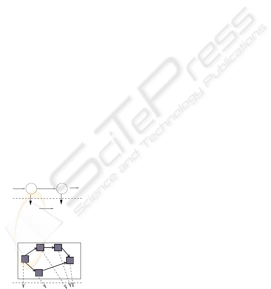
Pipelined Execution of Workflows. The chained
service model allows a pipelined execution of work-
flows. If a workflow A produces data for a workflow
B, A and B can be executed concurrently if A and B
work on different data subsets: while B works on the
data set produced by A in the previous time step, A
starts to execute on the next data set, see Fig. 5 for an
illustration. There has to be a synchronization point
to ensure that B does not start its execution before A
has entirely finished its computations on the data set.
Moreover, the data set computed by A has to be made
available to B. If the executing cores share a common
address space, this can also be performed by synchro-
nization. Otherwise, communication has to be per-
formed.
To avoid waiting times when transferring data
from A to B, the execution of A and B should take
about the same time. The pipelined execution model
can be extended to an arbitrary sequence of chained
workflows, such that each workflow is executed on a
different core by a separate workflow engine.
Parallel Execution of a Single Workflow. The par-
allel execution of a single workflow can be obtained
by assigning the tasks of the workflow to different
workflow engines running on different cores of a
multi-core processor.
Two tasks t and s of the same workflow A can be
assigned to different workflow engines for a parallel
execution, if there is no control or data dependence
A B
b1 b2 b3
core1 core2
communication
mapping to cores
Figure 5: Pipelined workflow execution for the chained ser-
vice model.
A
2
A
3
A
4
A
5
A
1
core2 core3
to cores
mapping
core1
workflow A
Figure 6: Parallel execution of a single workflow.
relation between t and s and if both t and s have to be
executed, i.e. t and s are not in an exclusive choice
relation. There is a data dependence between t and s,
if t produces data which is used by s (or vice versa)
or if t and s manipulate the same data. The maximum
degree of parallelism of a workflow W can be defined
as the maximum number of tasks of W that can be ex-
ecuted in parallel. This parallel execution model can
be applied to separate workflows in the chained ser-
vice model, the nested sub-process model, the peer-
to-peer model, and the parallel synchronized model,
see Fig. 6 for an illustration. The internal structure
of the workflows can be described by workflow pat-
terns like sequence, parallel split or exclusive choice
(van der Aalst et al., 2003). For each of these patterns,
a process-based description using CSP (Communicat-
ing Sequential Processes) (Hoare, 1985) can be given
(Wong and Gibbons, 2007). Section 4 presents a par-
allel execution model for the parallel execution of the
tasks of a single workflow.
Parallelism can also be exploited for the execu-
tion of a single task if its execution involves a signi-
ficant amount of computation as it might be the case
for tasks in an e-science workflow. In this case, the
task is assigned to a group of execution cores instead
to a single core. To exploit this kind of parallelism,
the task has to have a suitable internal computation
structure which allows a parallel execution. This can
be a data parallel structure such that independent ex-
ecution units work on different data, or if the task ex-
hibits an internal task structure such that independent
computations can be executed in parallel.
The parallel execution of a single task is also pos-
sible if the nested subprocess model is used: if a task
of workflow A is encapsulated and executed as a sepa-
rate workflow B, the execution of B can be performed
in parallel, if B has a suitable structure with indepen-
dent sub-tasks.
Concurrent Execution of Different Workflows.
The parallel synchronized model allows the concur-
rent execution of different workflows using workflow
engines on different execution cores. The workflow
engines can work independently executing different
workflows A and B. At synchronization points bet-
ween predefined tasks of A and B, a common event is
generated which stops the execution of A until the ex-
ecution of B reaches the predefined synchronization
point, and vice versa. Fig. 7 shows an illustration.
Synchronization may also be required when dif-
ferent workflows that are executed concurrently on
different cores of the same processor access the same
data sets that are stored locally; this access has to be
synchronized if write accesses are performed. If all
ICEIS 2008 - International Conference on Enterprise Information Systems
224

A B
core1 core2
synchronization
synch.
mapping to cores
Figure 7: Concurrent execution of workflows with synchro-
nization.
A
1
B
3
A
4
A
3
B
2
A
2
A
5
B
1
B
4
B
5
core4
core3 core1 core2
to cores
mapping
B
A
Figure 8: Mixed execution of workflows.
A B
workflow engine
core1 core2
mapping to cores
Figure 9: Parallelism within a workflow engine.
data accesses are performed via a database, the syn-
chronization is usually performed in the database.
Mixed Executions. The different modes for a par-
allel execution can be mixed in different ways. For
example, a concurrent execution of workflows can be
mixed with a parallel execution of a single workflow
in the sense that different groups of cores work on dif-
ferent workflows where each group executes its work-
flow in parallel by distributing the tasks to different
cores for execution, see Fig. 8.
Similarly, a pipelined execution of workflows can
be combined with a parallel execution of a single
workflow by using groups of execution cores for each
stage of the execution pipeline.
Parallelism within the Workflow Engine. The
parallel execution of a single workflow can also be
performed if the workflow engine is multi-threaded
and can therefore execute different tasks by concur-
rent threads of control, see Fig. 9. Again, dependen-
cies between tasks have to be taken into account. This
kind of parallelism requires a parallel implementation
of the workflow engine itself.
4 MODEL FOR PARALLEL
WORKFLOW EXECUTION
This section gives a concise description of workflows
and presents an execution model which can be used
for the scheduling of the tasks of a workflow to differ-
ent cores.
There are some similarities between workflow ex-
ecutions and the execution of multiprocessor task (M-
task) graphs from scientific computing. Both prob-
lems deal with parallel execution of tasks with depen-
dencies where each task can in principle be executed
by several cores in parallel. The dependencies defined
may require a sequential execution of specific tasks.
There are several differences between workflows and
M-task graphs: M-task scheduling usually assumes
a distributed address space and, therefore, the execu-
tion model has to take redistribution operations into
consideration, see (Rauber and R¨unger, 1998) for a
formal description. For workflow execution on multi-
core architectures, there is a shared address space and
no communication for redistribution operations are
required. Moreover, workflows may contain exclu-
sive choice patterns, i.e. only one of two or more tasks
without dependencies has to be executed. This does
not occur in M-task graphs. In the following, we for-
mulate the parallel execution of workflows with the
mechanisms used for M-task graphs employing a use-
ful adaption (Rauber and R¨unger, 1998). This allows
us to apply the scheduling theory for M-task programs
to the parallel execution of workflows.
A workflow consists of a collection of nodes
J
1
,...,J
Ω
where each node represents a service or task
to be executed. Nodes need not to be independent of
each other but may be related by a precedence relation
⊲ which is caused by a control or data dependency:
J
i
⊲ J
k
if there is a dependence from J
i
to J
k
.
The execution of different tasks of a workflow on dif-
ferent execution units has to guarantee that the input
data required by a node J
k
are available when the ex-
ecution of J
k
starts, i.e.:
(i) The input data must have been produced by pre-
decessor J
i
of J
k
with J
i
⊲ J
k
.
(ii) The input data must be available in the expected
format, i.e. each execution unit must have the data
that it needs for the execution of its nodes.
Item (i) is satisfied when executing the nodes ac-
cording to the precedence relation. To satisfy (ii), a
re-organization between nodes J
i
and J
k
with J
i
⊲ J
k
might be necessary to re-arrange the data that have
been output by J
i
in order to get the format expected
by J
k
.
A workflow can be represented as a DAG G =
(V,E). The nodes of the DAG are the nodes V =
MODELS FOR PARALLEL WORKFLOW PROCESSING ON MULTI-CORE ARCHITECTURES
225

{J
1
,... ,J
Ω
} and the edges are defined according to
the precedence relation (i.e., (J
i
,J
k
) ∈ E if J
i
⊲ J
k
). In
the following we identify a workflow with its DAG
representation. We assume that J
1
,... ,J
Ω
are sorted
topologically, i.e. if J
i
⊲ J
k
then i < k.
4.1 Parallel Execution of Workflows
A node of the workflow DAG can be executed on a
single execution core or on multiple execution cores,
if the node exhibits an internal structure as it is, e.g.,
the case for the nested sub-process model. In the fol-
lowing, we consider the general case that multiple ex-
ecution cores may be used for a single node.
To capture the parallel execution of workflows, the
nodes of a workflowDAG are attached with cost func-
tions T describing the global execution time as a func-
tion of the number of execution cores q ∈ {1, ..., p}
executing J ∈ V :
T : V × [1,. . ., p] → IR
T(J,q) = T
comp
(J, q) + T
admin
(J, q)
where T
comp
(J, q) = T
comp
(J, 1)/q + T
overhead
is the
core execution time. T
overhead
denotes the overhead
caused by the parallel execution (e.g. waiting times)
of a node on several execution cores. T
admin
(J, q) de-
scribes the costs for the administration which is nec-
essary to arrange the execution of a node on several
execution cores including the internal data accesses
and communication.
In addition, there may be costs to perform
re-arrangement between cooperating nodes. Such
costs arise, e.g., if cooperating nodes require dif-
ferent arrangements for the same data. The neces-
sary re-arrangements are performed by specific re-
arrangement operations that have to be performed
between the execution of nodes J and J
′
for J ⊲ J
′
.
The costs are captured by a re-arrangement function
Re(J,J
′
). The costs of the re-arrangement functions
T
Re
: V
2
× [1, ..., p]
2
→ IR are attached to the edges
of the workflow DAG. For J ⊲ J
′
, T
Re
(J, J
′
,q,q
′
) de-
scribes the re-arrangement costs between J and J
′
for
the case that J and J
′
are executed by q and q
′
exe-
cution cores, respectively. T
Re
(J, J
′
,q,q
′
) = 0 holds if
no re-arrangement is needed between J and J
′
.
4.2 Scheduling of Workflow DAGs
The parallel execution of a workflow can be captured
by a scheduling function S performing an assignment
of an execution time interval and a subset Π
i
of the
executing cores to each node. The execution time in-
terval begins at a start time s
i
:
S : {J
1
,... ,J
Ω
} → IR× 2
P
S (J
i
) = (s
i
,Π
i
)
Definition 1. (Feasible Scheduling) A schedule for a
workflow is feasible if for all i, j = 1,... ,Ω, the fol-
lowing conditions hold:
(a) s
i
+ T(J
i
,|Π
i
|) + T
Re
(J
i
,J
j
) ≤ s
j
for J
i
⊲ J
j
(b) If [s
i
,s
i
+ T
g
(J
i
,Π
i
)] ∩ [s
j
,s
j
+ T
g
(J
j
,Π
j
)] 6=
/
0
then Π
i
∩ Π
j
=
/
0 where
T
g
(J
i
,Π
i
) = T(J
i
,|Π
i
|) +
∑
Re∈R E
T
Re
(J
i
,J
j
).
R E contains the re-arrangement operations be-
tween J
i
and its successors {J
j
|J
i
⊲ J
j
}.
Condition (a) expresses that dependent nodes
have to be executed one after another according to the
precedence relations. Condition (b) expresses that in-
dependent nodes must be executed on disjoint sets of
execution cores if their execution time intervals over-
lap. This includes that the number of active execution
cores can never exceed the total number of execution
cores. The execution time intervals also comprise the
time for the execution of re-arrangement functions to
establish the correct data arrangement for subsequent
nodes.
The total execution time Γ of a feasible schedule
S for a workflow DAG is
Γ(S ) = max
i=1,...Ω
n
s
i
+ T
g
(J
i
,Π
i
)
o
The scheduling problem is to determine an optimal
feasible schedule S , i.e., a feasible schedule that min-
imizes the objective function Γ(S ).
A linear chain of nodes of a workflow always has
to be executed sequentially one after another; usually
the same execution unit should be used to avoid re-
arrangement operations. We can therefore normalize
workflow DAGs:
Definition 2
. (Normalized DAG) Let G = (V,E) be a
workflow DAG. A linear chain of nodes is a subgraph
G
′
of G consisting of a subset of nodes {J
′
1
,... ,J
′
ω
} ⊂
V such that for i = 1,..., ω − 1:
if there exists J with J
i
⊲ J then J = J
i+1
.
A maximum linear chain of nodes is a linear chain
which is no proper subgraph of another linear chain
of the DAG G. A normalized workflow DAG is a work-
flow DAG without linear chains of nodes.
By a suitable fusion of nodes, each workflowDAG
can be transformed into a normalized workflow DAG
that does not contain linear chain of nodes.
Definition 3
. (Normalization of workflow DAGs) Let
G be a workflow DAG with m maximal linear chains
C
1
,... ,C
m
. Each of the chains C
j
= {J
′
1
,... ,J
′
ω
j
} is
ICEIS 2008 - International Conference on Enterprise Information Systems
226

identified with one new node
˜
J
j
, j = 1,..., m, which
has costs
˜
T(
˜
J
j
,|Π
j
|) =
ω
j
∑
i=1
T(J
′
i
,|Π
j
|).
The normalization of DAGs is a restriction of the
potential solution space of feasible schedules. The re-
striction has the effect that the same execution cores
are assigned to each node of a linear chain in the
original DAG. This is a reasonable assumption, be-
cause a change in the executing cores may require
a re-arrangement of data. The costs of such a re-
arrangement is usually much larger than the benefits
of a change in the number of executing processors.
Normalized workflow DAGs can be used for the
scheduling of workflows on multiple execution cores,
as they are provided by multi-core architectures. The
model also captures a parallel workflow execution on
distributed architectures where each site provides pro-
cessors with multiple execution cores. Communica-
tion abstractions for the distributed execution of busi-
ness processes are described in (Aldred et al., 2007).
5 CONCLUSIONS
The widespread use of multi-core processors provides
new computing possibilities, since software develop-
ers can improve their applications with new function-
alities which can be provided by separate threads of
control running on a separate core of the processor.
To exploit this improvement, parallel programming
techniques must be applied. This is also the case for
business software whose execution is often based on
workflow model.
In this article, we have explored different possibil-
ities for a parallel execution of workflow based on dif-
ferent interoperability models. The article provides a
detailed model for the parallel execution of workflows
and considers the scheduling of workflows based on
this model.
REFERENCES
Adl-Tabatabai, A., Kozyrakis, C., and Saha, B. (2006). Un-
locking concurrency. ACM Queue, 4(10):24–33.
Aldred, L., van der Aalst, W., Dumas, M., and ter Hof-
stede, A. (2007). Communication Abstractions for
Distributed Business Processes. In 19th Int. Conf.
on Advanced Information System Engineering (CAiSE
2007), Springer LNCS 4495, pages 409–423.
Asanovic, K., Bodik, R., Catanzaro, B., Gebis, J., Hus-
bands, P., Keutzer, K., Patterson, D., Plishker, W.,
Shalf, J., Williams, S., and Yelick, K. (2006). The
Landscape of Parallel Computing Research: A View
from Berkeley. Technical Report UCB/EECS-2006-
183, EECS Department, University of California,
Berkeley.
Azimi, M., Cherukuri, N., Jayasimha, D., Kumar, A.,
Kundu, P., Park, S., Schoinas, I., and Vaidya, A.
(2007). Integration Challenges and Tradeoffs for Tera-
scale Architectures. Intel Technology Journal, 11(03).
Dongarra, J., Gannon, D., Fox, G., and Kennedy, K. (2007).
The Impact of Multicore on Computational Science
Software. CTWatch Quarterly, 3(1).
Held, J., Bautista, J., and Koehl, S. (2006). From a Few
Cores to Many – A Tera-Scale Computing Research
Overview. Intel White Paper, Intel.
Hoare, C. (1985). Communicating Sequential Processes.
Prentice Hall.
Hollingsworth, D. (1995). The Workflow Reference Model.
Technical report, The Workflow Management Coali-
tion.
Intel (2006). Intel Multi-Core Processor Architecture De-
velopment Backgrounder. Technical report, Intel
White Paper.
Koch, G. (2005). Discovering Multi-Core:Extending the
Benefits of Moore’s Law. Intel White Paper, Technol-
ogy@Intel Magazine.
Kogge, P. (2005). An Exploitation of the Technology Space
for Multi-Core Memory/Logic Chips for Highly Scal-
able Parallel Systems. In Proceedings of the In-
novative Architecture for Future Generation High-
Performance Processors and Systems. IEEE.
Kuck, D. (2005). Platform 2015 Software-Enabling Inno-
vation in Parallelism for the next Decade. Intel White
Paper, TechnologyIntel Magazine.
Marr, D., Binus, F., Hill, D., Hinton, G., Konfaty, D., Miller,
J., and Upton, M. (2002). Hyper-Threading Technol-
ogy Architecture and Microarchitecture. Intel Tech-
nology Journal, 6(1):4–15.
Rauber, T. and R¨unger, G. (1998). Compiler Support for
Task Scheduling in Hierarchical Execution Models.
Journal of Systems Architecture, 45:483–503.
Reinders, J. (2006). Sea Change in the Software World.
Intel Software Insight, pages 3–8.
Sutter, H. (2005). The free lunch is over – a fundamental
turn toward concurrency in software. Dr.Dobb’s Jour-
nal, 30(3).
Sutter, H. and Larus, J. (2005). Software and the Concur-
rency Revolution. ACM Queue, 3(7):54–62.
van der Aalst, W., ter Hofstede, A., Kiepuszewski, B., and
Barros, A. (2003). Workflow Pattern. Distributed and
Parallel Databases, 14(3):5–51.
Wong, P. and Gibbons, J. (2007). A Process-Algebraic Ap-
proach to Workflow Specification and Refinement. In
Proceedings of 6th International Symposium on Soft-
ware Composition.
MODELS FOR PARALLEL WORKFLOW PROCESSING ON MULTI-CORE ARCHITECTURES
227
