
FAST SPATIALLY CONTROLLABLE 2D/3D TEXTURE SYNTHESIS
AND MORPHING FOR MULTIPLE INPUT TEXTURES
Felix Manke and Burkhard W
¨
unsche
Graphics Group, Department of Computer Science, University of Auckland, Private Bag 92019, Auckland, New Zealand
Keywords:
Exemplar-based texture synthesis, Texture morphing, Solid texture, Appearance space.
Abstract:
Texture synthesis and morphing are important techniques for efficiently creating realistic textures used in sci-
entific and entertainment applications. In this paper we present a novel fast algorithm for multi-dimensional
texture synthesis and morphing that is especially suitable for parallel architectures such as GPUs or direct
volume rendering (DVR) hardware. Our proposed solution generalizes the synthesis process to support higher
than three-dimensional synthesis and morphing. We introduce several improvements to previous 2D synthesis
algorithms, such as new appearance space attributes and an improved jitter function. We then modify the
synthesis algorithm to use it for texture morphing which can be applied to arbitrary many 2D input textures
and can be spatially controlled using weight maps. Our results suggest that the algorithm produces higher
quality textures than alternative algorithms with similar speed. Compared to higher quality texture synthesis
algorithms, our solution is considerablly faster and allows the synthesis of additional channels without affect-
ing the running time of the synthesis at all. The method is easily extended to allow fast 3D synthesis and as
another novel contribution we show several examples for morphed solid 3D textures. Overall the presented
technique provides an excellent trade-off between speed and quality, is highly flexible, allows the use of arbi-
trary channels such as transparencies and displacement maps, can be extended to arbitrary dimensions and is
suitable for a GPU-implementation.
1 INTRODUCTION
Texture mapping is one of the most important tech-
niques to increase the realism of a 3D scene by pro-
viding fine surface details. Exemplar-based 2D tex-
ture synthesis is a powerful tool to generate large tex-
tures from small input examples. Texture morphing
as an extension creates coherent transitions between
entirely different materials with a quality and flexi-
bility that cannot be achieved using simple blending
techniques. The applications of texture morphing are
manifold and include terrain rendering, scientific vi-
sualization, the creation of transitions in animal fur
and between biomedical or geological materials, and
the simulation of aging processes.
3D solid textures have the advantage that, in con-
trast to 2D textures, objects can be “carved” out of a
3D material resulting in more realistic results. Since
the acquisition of 3D textures is difficult, the synthesis
and morphing of solid textures from 2D exemplars is
very important. However, the task is extremely chal-
lenging and usually requires long computation times.
In this paper, we present a new fast algo-
rithm for exemplar-based 2D texture morphing and
higher-dimensional texture synthesis and morphing.
Our texture morphing algorithm is based on Lefeb-
vre and Hoppe’s pixel-based texture synthesis algo-
rithm (Lefebvre and Hoppe, 2005), a real-time ap-
proach implemented on the GPU by utilizing the
parallel synthesis scheme proposed by L. Wei (Wei,
2003).
Because of the close relationship we will give a
brief summary of the original synthesis algorithm in
section 3 before discussing the extensions we made
to support texture morphing of arbitrary many input
exemplars in 2D (section 4) and 3D (section 5). In
section 6 we discuss our results and conclude with an
outlook on future research in section 7.
2 RELATED WORK
Texture synthesis and texture morphing are closely re-
lated fields in which numerous different algorithms
5
Manke F. and Wünsche B. (2009).
FAST SPATIALLY CONTROLLABLE 2D/3D TEXTURE SYNTHESIS AND MORPHING FOR MULTIPLE INPUT TEXTURES.
In Proceedings of the Fourth International Conference on Computer Graphics Theory and Applications, pages 5-12
DOI: 10.5220/0001772800050012
Copyright
c
SciTePress

have been proposed. Procedural techniques for both
2D and 3D texture synthesis (Perlin, 1985; Turk,
1991; Witkin and Kass, 1991; Worley, 1996) proofed
to be hard to control and, compared to exemplar-based
methods, were limited in the types of materials that
can be modeled. Parametric exemplar-based meth-
ods, as proposed in (Heeger and Bergen, 1995; De
Bonet, 1997; Bar-Joseph et al., 2001), rely on mod-
els of global statistical properties which serve as con-
straint function while matching statistics of the input
and target texture. Though extensions for 3D synthe-
sis have been made (Heeger and Bergen, 1995; Dis-
chler et al., 1998), parametric models are usually only
successful in synthesizing homogeneous and stochas-
tic exemplars. Mixing properties of different textures
is possible, but for texture morphing not enough spa-
tial control is offered. Patch-based methods paste
random patches of the exemplar into the output tex-
ture and optimize the transitions between the over-
lapping patches (Praun et al., 2000; Efros and Free-
man, 2001; Kwatra et al., 2003). While these methods
could probably be extended to use 3D texture patches
as input, there is no straightforward way to use them
to generate 3D textures from a 2D input. Indeed,
we believe it is questionable whether such techniques
can be used to create texture morphing of acceptable
quality at all (though Kwatra et al. placed flower
textures onto a grass texture and optimized the grass
seams (Kwatra et al., 2003)). In contrast, by process-
ing one pixel at a time pixel-based methods (Efros
and Leung, 1999; Wei and Levoy, 2000; Ashikhmin,
2001; Lefebvre and Hoppe, 2005) offer a control that
is fine enough to allow texture synthesis and mor-
phing in 2D and 3D at a high quality. A successful
3D synthesis has been shown by L. Wei (Wei, 2002;
Wei, 2003). Finally, optimization-based approaches
use the local similarity measures of pixel neighbor-
hoods to define a global texture energy function that
is minimized (Kwatra et al., 2005). Recently, Kopf
et al. demonstrated that energy-based methods can be
used for 3D synthesis (Kopf et al., 2007), though the
synthesis times are with up to 90 minutes rather slow
and a GPU implementation non-trivial. Another spe-
cialized solution for synthesizing 3D composite mate-
rials based on stereology theories (the analysis of 2D
cross-sections of 3D volumes) has been proposed by
Jagnow et al. (Jagnow et al., 2004).
Algorithms specifically for 2D texture morphing
have also been developed. L. Wei used his pixel-
based method to create transitions between two ex-
emplars (Wei, 2003). However, the synthesis quality
decreased significantly. Liu et al. proposed a pattern-
based approach that uses ideas of image morphing to
generate metamorphosis sequences (Liu et al., 2002).
Both Zhang et al. and Tonietto and Walter used tex-
ton maps to support a pixel-based texture morph-
ing (Zhang et al., 2003; Tonietto and Walter, 2005).
Unfortunately, all three publications show results only
for very similar input exemplars. Matusik et al. uti-
lized a simplical complex model to build a neigh-
borhood graph of input exemplars (Matusik et al.,
2005). Though examples with several input textures
are given, the approach relies on a texture database
and is explicitly designed for similar textures only. To
our knowledge, texture morphing in three dimensions
using exemplars of very different irregularly textured
materials has not been shown by anyone before.
3 LEFEBVRE AND HOPPE’S 2D
TEXTURE SYNTHESIS
As most pixel-based methods, the algorithm proposed
in (Lefebvre and Hoppe, 2005; Lefebvre and Hoppe,
2006) performs an iterative optimization to minimize
the difference of the synthesis result to the original ex-
emplar, where the distance is measured using the sum
of squared differences (SSD) of local neighborhoods.
A standard multi-resolution approach is pursued by
computing a Gaussian pyramid E of the exemplar and
creating an “empty” pyramid S for the synthesis re-
sult. The synthesis is performed from the coarsest to
the finest resolution, first establishing low frequencies
and then defining the fine details.
A key difference of the algorithm to other methods
is the fact that S does not store image colors, but pixel
coordinates into the exemplar E in order to enable a
GPU implementation. To pass the synthesis result of
a coarse level S
i−1
to a finer level S
i
an upsampling of
the coordinates is performed that distributes the value
of S
i−1
(P) (that is, a coordinate into E
i
) to four child
pixels in S
i
. In the correction phase, the synthesis
error is minimized by searching the pixel coordinate
Q with the best-matching local neighborhood N
E
i
(Q)
in the exemplar for the neighborhood N
S
i
(P) around
S
i
(P). The correction phase is accelerated using sub-
passes, each of which optimizes only selected pixels,
and k-coherence search (Tong et al., 2002) based on
pre-computed candidate sets.
The texture synthesis can greatly benefit by using
an appearance space (Lefebvre and Hoppe, 2006),
where pixels encode texture characteristics in addition
to color. The high-dimensional appearance vectors
are projected into a low-dimensional space defined by
the first n principal components obtained from a prin-
cipal component analysis (PCA). In tests we found
that usually more than 95% of the total variance of an
exemplar is explained by the first 8 components.
GRAPP 2009 - International Conference on Computer Graphics Theory and Applications
6

4 OUR 2D TEXTURE MORPHING
ALGORITHM
When dealing with texture morphing we have to syn-
thesize a texture based on several input exemplars.
The result should reflect the nature of all exemplars,
though the influence of each input can vary spatially.
To control the spatial influence of each of the m ex-
emplars, we use scalar weight maps of the size of the
synthesized texture S. Each weight map W
j
encodes
the weight of the exemplar E
j
per position P ∈ S. To
ensure a correct morphing, we normalize the weight
maps so that
∑
m
j=1
W
j
(P) = 1. Note that, when speci-
fying only one input exemplar, our algorithm behaves
like a standard texture synthesis algorithm.
In the following, we will discuss the extensions we
made for every single step of the original synthesis al-
gorithm. Because the coordinate upsampling remains
unchanged and is performed on each S
j
i
individually,
we do not include it in the discussion. Note that the
modifications necessary for texture morphing still al-
low an implementation on parallel architectures.
4.1 Initialization
The initialization of the exemplars themselves re-
mains unchanged, because they are independent from
each other. For every weight map W
j
that is associ-
ated with each exemplar, we additionally compute a
Gaussian pyramid. Because the algorithm is based on
manipulating exemplar coordinates rather than colors
(and coordinates cannot be averaged or merged), we
need a separate synthesis pyramid S
j
for every ex-
emplar. Instead of initializing S
j
−1
with zero coordi-
nates, we find the following initialization more intu-
itive (where s
e
j
is the size of E
j
):
S
−1
(P) = P mod s
e
j
,
as this better reflects how the algorithm proceeds, es-
pecially when only a few pyramid levels are used.
4.2 Coordinate Jitter
The coordinate jitter is also independent for each
exemplar. We propose a more intuitive jitter function
that has a more uniform distribution than the function
proposed by (Lefebvre and Hoppe, 2005):
J
i
(P) =
j +
k
x
k
y
, where
j = H(P) · lerp(0.5,1,r
i
),
k
x|y
=
lerp(0.5,2/3, r
i
) if j
x|y
≥ 0
1 − lerp(0.5, 2/3,r
i
) otherwise,
lerp(a,b,t) = a +t(b − a).
4.3 Correction Phase
In the correction phase the best-matching pixel for a
synthesis pixel P is searched in the exemplar. How-
ever, now S
i
(P) must represent all input exemplars,
weighted according to the weights W
j
i
(P). For the
original 2D synthesis algorithm the neighborhood of
P in the synthesis level S
i
can be defined as the set:
N
S
i
(P) = {E
i
(Q) | Q = S
i
(P + ∆
N
)}, ∆
N
∈ N , (1)
where ∆
N
takes the values of offset vectors from the
neighborhood’s center to all pixels in the neighbor-
hood as defined by the set N of all offsets:
N = {δ | (P + δ) ∈ N(P)}.
For the texture morphing of multiple exemplars,
we extend the neighborhood gathering as follows:
N
S
i
(P) = {C(i,P + ∆
N
)}, ∆
N
∈ N , (2)
C(i, X) =
m
∑
j=1
W
j
i
(X) · E
j
i
(Q), Q = S
j
i
(X).
C(i, X) the synthesized color in level i at location X
as the weighted average of all exemplar levels. Given
the synthesis neighborhood N
S
i
(P) the best-matching
pixel is searched for in each of the exemplars E
j
i
and
S
j
i
(P) where N
S
i
(P) is the same for all m synthesis
levels S
j
i
(P):
S
i
(P) = argmin
Q∈E
i
SSD(N
S
i
(P),N
E
i
(Q)). (3)
5 3D TEXTURE SYNTHESIS AND
MORPHING
In the following, we will discuss how to generate tex-
tures with an additional spatial dimension and morph
between different materials. As illustrated in figure 1,
several input exemplars are considered as being dif-
ferent views of the solid texture cube that is to be syn-
thesized (Wei, 2002; Kopf et al., 2007). During the
synthesis, the algorithm tries to generate a 3D tex-
ture that reflects the characteristics of all views. The
close relationship to 2D texture morphing in terms of
the use of multiple exemplars was already mentioned
by L. Wei (Wei, 2002). To create smooth transitions
between entirely different materials within the solid
texture cube, exemplar views need to be specified for
each material. For 3D morphing the weight maps are
used as in the 2D morphing to define the spatial influ-
ence of the materials. Our algorithm gives a unified
tool for supporting 3D synthesis or morphing at the
same time.
FAST SPATIALLY CONTROLLABLE 2D/3D TEXTURE SYNTHESIS AND MORPHING FOR MULTIPLE INPUT
TEXTURES
7
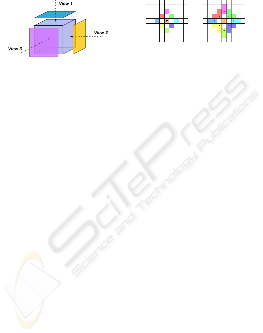
Figure 1: Several 2D exemplars define different views of the
solid texture being synthesized. Adopted from (Wei, 2002).
It is not always necessary or appropriate to specify
all three exemplars. Sometimes, for example when a
material exhibits dominant directional features, it is
better to define only two views (Wei, 2002).
The jitter step is not affected by our modifica-
tions, because the coordinates stored in a synthesis
level S
j
i
(P) are still defined in R
2
. A minor difference
is that the jitter function J
i
(P) and the hash function
H(P) now take 3D coordinates as input argument.
5.1 Initialization
In contrast to the 2D morphing, the synthesis pyra-
mids S
j
and the weight maps W
j
are solid texture
cubes. In S
j
each voxel stores a 2D coordinate into
the corresponding exemplar E
j
. Because E
j
repre-
sents only one particular view onto the solid target
texture, the initialization of S
j
−1
is modified in the fol-
lowing way:
S
j
−1
(P) = P
u,v
mod s
e
j
,
where u and v denote the two components of P ∈ R
3
to which E
j
is parallel.
5.2 Coordinate Upsampling
The coordinate upsampling cannot simply be ex-
tended by an additional dimension, because the syn-
thesis pyramids still store 2D coordinates. Thus, we
apply the 2D upsampling for every second slice that
is oriented parallel to the exemplar view and duplicate
the result for each subsequent slice:
S
j
i
(2 · P
u,v|w
+ ∆
u,v
) = S
j
i
(2 · P
u,v|(w+1)
+ ∆
u,v
) = (4)
(2 · S
i−1
(P) + ∆
U
) mod S
e
j
,
where w is even (w mod 2 = 0) and depicts the com-
ponent of P that is orthogonal to the view. ∆
u,v
de-
scribes a 3D vector with the same value in the u- and
v-component as ∆
U
and w = 0.
Figure 2: Left: Pixels used in our half-reduced neighbor-
hood. On the right, all pixels are shown that are included
when computing the averaged values of the neighborhood.
5.3 Correction Phase
When performing neighborhood-matching during the
correction phase we have to deal with the problem
that neighborhoods around voxels in a 3D synthesis
pyramid have to be compared with neighborhoods of
pixels of a 2D input exemplar. As a solution we take
advantage of the fact that the exemplars are oriented
and stand orthogonal to one of the principal axes of
the solid cube that is synthesized. Since the exem-
plar represents only the view in this direction, the syn-
thesis pyramid for this particular exemplar also only
needs to reflect the exemplar in the same direction.
Thus, we can align the 2D neighborhoods N
S
i
(P) to
stand parallel to the exemplar, as it has also been pro-
posed in (Wei, 2002; Kopf et al., 2007).
In consequence, we need to introduce several syn-
thesis neighborhoods N
S
i
|u,v
(P), one for each possible
orientation of exemplars. Note that, as in the 2D mor-
phing algorithm, N
S
i
|u,v
(P) is a merged neighborhood
that needs to represent all exemplars. Our definition
in equation 2 is also valid for the 3D synthesis, except
that P ∈ S
j
i
is now defined in R
3
. We therefore modify
the definition to support oriented neighborhood gath-
ering in 3D solid textures:
N
S
i
|u,v
(P) = {C(i,P + ∆
N|u,v
)}, ∆
N|u,v
∈ N
u,v
, (5)
where ∆
N|u,v
gives the neighborhood offsets parallel
to the current view (and the w-component set to 0).
Notice the similarity to the upsampling step, which
also depends on the view’s orientation.
Interleaved correction for an improved conver-
gence using sub-passes is still possible in 3D synthe-
sis and morphing. However, because of the additional
dimension we now have to define eight sub-passes as
a pattern in a 2
3
cube.
5.4 A New Neighborhood
As discussed in section 3, the synthesis in the reduced
appearance space makes it possible to use a very com-
pact neighborhood consisting of only 4 corner pixels.
GRAPP 2009 - International Conference on Computer Graphics Theory and Applications
8
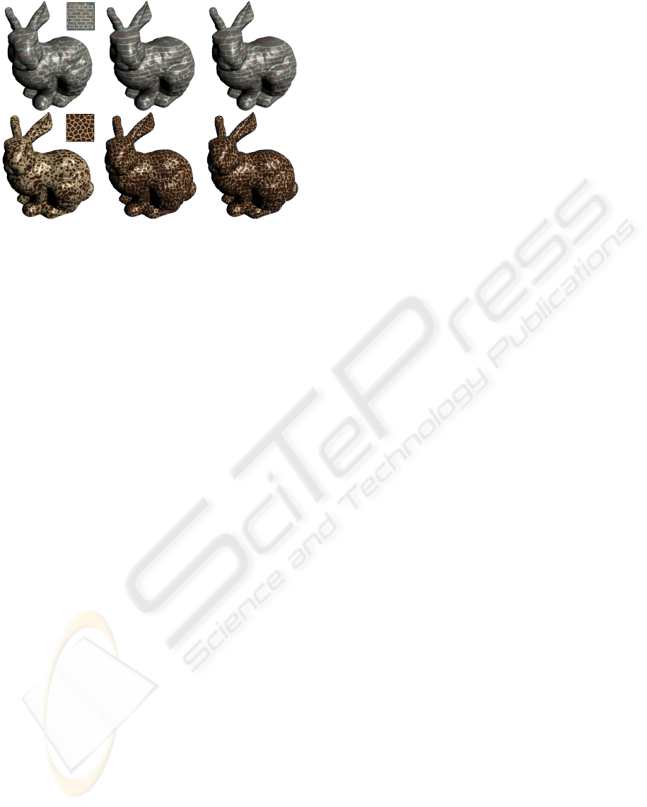
Figure 3: Comparison of different neighborhoods used dur-
ing the correction phase of the 3D texture synthesis. First
column: Reduced four-pixel neighborhood. Second col-
umn: Full 5×5 neighborhood consisting of 25 pixels. Third
column: Our new half-reduced neighborhood consisting of
9 pixels.
However, 3D texture synthesis is a much more chal-
lenging problem. The algorithm generally has to deal
with little information that is available for generating
a solid texture out of only 2D exemplars. We found
that the reduced neighborhood is not capable of pre-
serving the features of the input exemplars. Much
better results can be achieved using a full 5×5 or
even 7×7 neighborhood — of course at the expense
of speed.
To improve the synthesis while keeping the com-
putation time low we propose a new “half-reduced”
neighborhood. The layout is shown in figure 2 (left).
We still average several pixel values to compute the
values for the individual neighborhood values (shown
on the right of the figure). Note that the new neighbor-
hood, consisting of 9 points, is a superset of the neigh-
borhood proposed in (Lefebvre and Hoppe, 2006).
Figure 3 shows a comparison of the results using
different neighborhoods for 3D synthesis. Clearly,
our new neighborhood is much better capable of pre-
serving feature coherence than the original four-pixel
neighborhood, which fails to produce acceptable re-
sults. The new neighborhood can also be used for 2D
texture synthesis and morphing. We found that 2D
morphing results are improved significantly for exem-
plars with semantic features.
5.5 Synthesis and Morphing of
Additional Channels
The synthesis and morphing based on texture coordi-
nates makes it possible to restore the exact location in
the original exemplar for each pixel in the synthesized
texture. Instead of a color image, the result of the syn-
thesis is a map of texture coordinates that is used to
sample the exemplars and output the final image.
Using this map of texture coordinates, we are able
to sample arbitrary input images, and not only the
color exemplar. Hence, additional channels — like
alpha channels, displacement maps, specularity maps,
etc. — can be synthesized without affecting the per-
formance of the synthesis/morphing at all. This is an
advantage over other methods that do not keep track
of the original pixel locations in the input exemplars.
6 RESULTS
We implemented our algorithm using C++ and exe-
cute it on the CPU in order to facilitate experimen-
tation and integration into existing biomedical visu-
alization software. As exemplars we used 64 ×64
or 128×128 pixel textures. For the 2D morphing,
the target size is 512×512. Our generated solid tex-
tures have 128
3
or 256
3
voxels. We used the ap-
pearance space attributes as discussed in section 3
and projected the 150-dimensional vectors onto the
first eight components using the PCA implementa-
tion from (Intel
R
Corporation, 2008). We performed
two full correction passes per synthesis level. For the
2D outputs we used the reduced or our half-reduced
neighborhood, for 3D synthesis and morphing the
half-reduced or a full 5×5 neighborhood.
Figure 4 shows 2D morphing results with two ex-
emplars to demonstrate how the transition between
structures is generated. Note how the algorithm grad-
ually defines a coherent transition of features and
morphs between them, even if the exemplars’ features
are extremely different. Figure 5 depicts morphings
with several exemplars and complex weight maps.
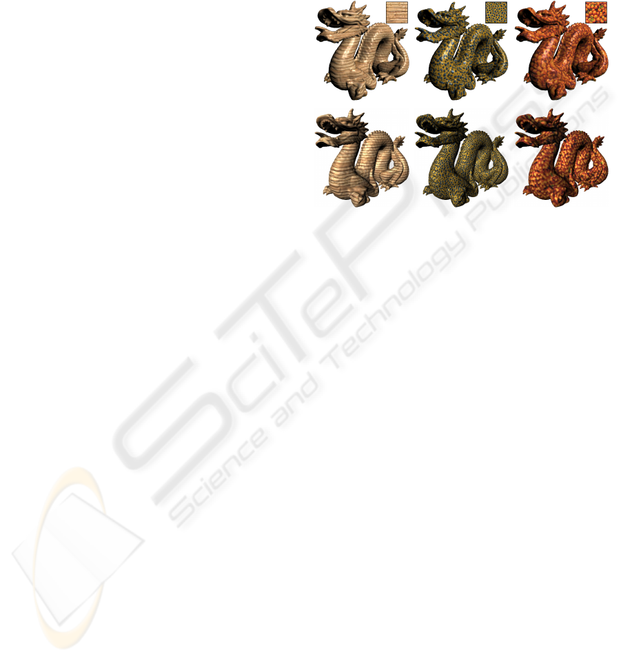
Examples of our 3D synthesis, including one with
additional channels for displacement mapping, and
morphing results are given in figures 6 and 7, respec-
tively. As can be seen, the generated 3D solid textures
coherently reflect the characteristics of the materials.
However, a smoothing of the fine details can be ob-
served — a problem that is common in solid texture
synthesis algorithms (compare for example to (Wei,
2003; Kopf et al., 2007)).
Using one core of a 2.13 GHz Intel
R
Core
TM
2
Duo CPU with 2 GB RAM the 2D morphing us-
ing two exemplars and a reduced neighborhood takes
only less than 12 seconds on average. With our half-
reduced neighborhood the timings are still below 17
seconds and examples with three and four exemplars
needed less than 18 and 25 seconds, respectively, for
the morphing with a reduced neighborhood.
For 3D synthesis, even with a full 7×7 neigh-
FAST SPATIALLY CONTROLLABLE 2D/3D TEXTURE SYNTHESIS AND MORPHING FOR MULTIPLE INPUT
TEXTURES
9
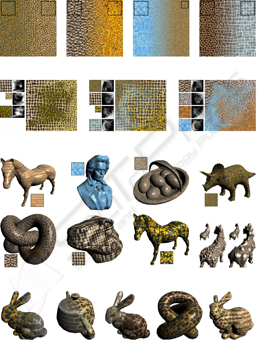
Figure 4: 2D morphing results using two input exemplars and linear weight maps. The examples illustrate how the morphing
algorithm finds coherent transitions between the features.
Figure 5: 2D morphing results using three and four input exemplars and complex weight maps. Note that the weight maps are
normalized and of the same size as the synthesized target texture.
Figure 6: 3D texture synthesis results. The generated solid textures have been used to render different 3D geometries. Bottom-
right: Intensity values used as additional channel for displacement mapping.
Figure 7: 3D morphing results using two exemplars and linear weight maps. The last two examples use a morphed texture of
size 256
3
.
GRAPP 2009 - International Conference on Computer Graphics Theory and Applications
10
borhood (which we almost never use in practice) our
algorithm needs no more than 15 minutes to syn-
thesize a 128
3
solid texture cube, and 3D morph-
ing with twice as many exemplar views takes less
than 30 minutes. The half-reduced neighborhood per-
forms with little more than 5 minutes for 3D synthe-
sis and about 12 minutes for 3D morphing very fast
while producing high-quality results. For morphing
solid textures with a resolution of 256
3
voxels, our
algorithm needs between 110 minutes (half-reduced
neighborhood) and 140 minutes (full 5×5 neighbor-
hood). Note that doubling the target resolution leads
to eight times as many voxels in the solid cube. With
an implementation on the GPU we would expect a
significant performance boost, possibly by several or-
ders of magnitude.
Our algorithm has some limitations. As most
pixel-based approaches the synthesis and morphing
sometimes fails for textures with large features or
where the features have a semantic meaning to hu-
mans. Problems also occur with near stochastic tex-
tures such as clouds and slightly crumbled paper. Tex-
tures with features of very different scale represent a
particular problem for the morphing, because no com-
mon structures can be found that could be morphed
into each other.
6.1 Comparison with Kopf et al.’s
Algorithm
In figure 8, we compare the synthesis quality of
our proposed algorithm with results of the algorithm
based on energy minimization recently presented by
(Kopf et al., 2007). Disregarding the different illumi-
nation settings, the results for the first two exemplars
(”woodwall” and ”animalskin”) appear to be of very
similar quality. Our result for the ”woodwall” tex-
ture seems to have more structure than Kopf et al.’s
result, which looks rather smooth. Although our re-
sult for ”animalskin” shows more variance in the size
of the features, it better reflects the structures within
the blue spots. On the other hand, the boundaries be-
tween texture features look sharper in Kopf et al.’s
solid texture, which can also be seen in the right hand
image, where features (the tomatoes) are more dis-
tinct and the green leaves are not suppressed as much.
However, our technique is significantly faster. Includ-
ing the initialization, we need about 6 minutes when
using the half-reduced neighborhood and less than 9
minutes using the full 5×5 neighborhood. In con-
trast, Kopf et al. reported up to 90 minutes required
for the synthesis. Another advantage of our proposed
method over Kopf et al.’s solution is the fact that ad-
ditional channels can be synthesized without affecting
the running of the synthesis at all. In contrast, the cost
of Kopf et al.’s method directly depends on the num-
ber of channels in the exemplar. Besides this, it has
to be pointed out that Kopf et al.’s algorithm does not
allow a straightforward implementation on the GPU,
because a continuous update of the histogram is re-
quired.
Figure 8: Comparison of 3D texture synthesis with Kopf et
al.’s results. Top row: Our synthesis results, using the half-
reduced neighborhood (left, right) and a full 5×5 neigh-
borhood (center), respectively. Bottom row: Results of
Kopf et al.’s algorithm with the same input exemplars and
target resolution (from http://www.johanneskopf.de/
publications/solid/results/index.html.)
7 CONCLUSIONS AND FUTURE
WORK
We presented a new and fast exemplar-based tex-
ture morphing algorithm for two, three and theoret-
ically also higher dimensions as an extension of the
pure 2D synthesis algorithm proposed in (Lefebvre
and Hoppe, 2005; Lefebvre and Hoppe, 2006). Be-
cause our modifications obey the design principles of
the original algorithm, our new contribution still al-
lows an implementation on parallel stream-processing
hardware. Even without hardware acceleration our
current CPU-based implementation is already faster
than comparable 3D synthesis methods. The steps
of the original algorithm have been generalized to
support morphing with arbitrary many exemplars and
higher-dimensional synthesis. A more intuitive jitter
function and a new compact neighborhood suitable
for fast 3D synthesis have been introduced and its per-
formance evaluated.
In the future we want to further improve the syn-
thesis quality. Spatially varying scaling based on the
dominant frequency of the exemplars could support
the morphing to create better transitions between ex-
FAST SPATIALLY CONTROLLABLE 2D/3D TEXTURE SYNTHESIS AND MORPHING FOR MULTIPLE INPUT
TEXTURES
11

emplars with structures of very different scale. An-
other interesting feature is the synthesis and morphing
along time-varying vector and tensor fields.
REFERENCES
Ashikhmin, M. (2001). Synthesizing natural textures. In
Proceedings of I3D ’01, pages 217–226, New York,
NY, USA. ACM Press.
Bar-Joseph, Z., El-Yaniv, R., Lischinski, D., and Werman,
M. (2001). Texture mixing and texture movie synthe-
sis using statistical learning. IEEE Transactions on
Visualization and Computer Graphics, 7(2):120–135.
De Bonet, J. S. (1997). Multiresolution sampling proce-
dure for analysis and synthesis of texture images. In
Proceedings of SIGGRAPH ’97, pages 361–368, New
York, NY, USA. ACM Press.
Dischler, J.-M., Ghazanfarpour, D., and Freydier, R. (1998).
Anisotropic solid texture synthesis using orthogonal
2d views. Computer Graphics Forum, 17(3):87–95.
Efros, A. A. and Freeman, W. T. (2001). Image quilting for
texture synthesis and transfer. In Proceedings of SIG-
GRAPH ’01, pages 341–346, New York, NY, USA.
ACM Press.
Efros, A. A. and Leung, T. K. (1999). Texture synthesis
by non-parametric sampling. In Proceedings of ICCV
’99, pages 1033–1038, Washington, DC, USA. IEEE
Computer Society.
Heeger, D. J. and Bergen, J. R. (1995). Pyramid-based
texture analysis/synthesis. In Proceedings of SIG-
GRAPH ’95, pages 229–238, New York, NY, USA.
ACM Press.
Intel
R
Corporation (2008). Open Source Computer Vision
Library. URL: http:// www.intel.com / technology /
computing/opencv/index.htm [checked: 05/27/2008].
Jagnow, R., Dorsey, J., and Rushmeier, H. (2004). Stere-
ological techniques for solid textures. ACM Transac-
tions on Graphics (Proceedings of SIGGRAPH ’04),
23(3):329–335.
Kopf, J., Fu, C.-W., Cohen-Or, D., Deussen, O., Lischinski,
D., and Wong, T.-T. (2007). Solid texture synthesis
from 2d exemplars. ACM Transactions on Graphics
(Proceedings of SIGGRAPH ’07), 26(3):(2.1)–(2.9).
Kwatra, V., Essa, I., Bobick, A., and Kwatra, N. (2005).
Texture optimization for example-based synthesis.
ACM Transactions on Graphics (Proceedings of SIG-
GRAPH ’05), 24(3):795–802.
Kwatra, V., Sch
¨
odl, A., Essa, I., Turk, G., and Bobick, A.
(2003). Graphcut textures: image and video synthe-
sis using graph cuts. ACM Transactions on Graphics
(Proceedings of SIGGRAPH ’03), 22(3):277–286.
Lefebvre, S. and Hoppe, H. (2005). Parallel controllable
texture synthesis. ACM Transactions on Graphics
(Proceedings of SIGGRAPH ’05), 24(3):777–786.
Lefebvre, S. and Hoppe, H. (2006). Appearance-space tex-
ture synthesis. ACM Transactions on Graphics (Pro-
ceedings of SIGGRAPH ’06), 25(3):541–548.
Liu, Z., Liu, C., Shum, H.-Y., and Yu, Y. (2002). Pattern-
based texture metamorphosis. In Proceedings of Pa-
cific Graphics ’02, page 184, Washington, DC, USA.
IEEE Computer Society.
Matusik, W., Zwicker, M., and Durand, F. (2005). Texture
design using a simplicial complex of morphable tex-
tures. ACM Transactions on Graphics (Proceedings
of SIGGRAPH ’05), 24(3):787–794.
Perlin, K. (1985). An image synthesizer. In Proceedings
of SIGGRAPH ’85, pages 287–296, New York, NY,
USA. ACM Press.
Praun, E., Finkelstein, A., and Hoppe, H. (2000). Lapped
textures. In Proceedings of SIGGRAPH ’00, pages
465–470, New York, NY, USA. ACM Press.
Tong, X., Zhang, J., Liu, L., Wang, X., Guo, B., and Shum,
H.-Y. (2002). Synthesis of bidirectional texture func-
tions on arbitrary surfaces. In Proceedings of SIG-
GRAPH ’02, pages 665–672, New York, NY, USA.
ACM Press.
Tonietto, L. and Walter, M. (2005). Texture metamorpho-
sis driven by texton masks. Computers & Graphics,
29(5):697–703.
Turk, G. (1991). Generating textures on arbitrary sur-
faces using reaction-diffusion. In Proceedings of SIG-
GRAPH ’91, pages 289–298, New York, NY, USA.
ACM Press.
Wei, L.-Y. (2002). Texture Synthesis by Fixed Neighbor-
hood Searching. PhD thesis, Stanford University.
Wei, L.-Y. (2003). Texture synthesis from multiple sources.
In SIGGRAPH ’03: ACM SIGGRAPH 2003 Sketches
& Applications, pages 1–1, New York, NY, USA.
ACM Press.
Wei, L.-Y. and Levoy, M. (2000). Fast texture synthesis
using tree-structured vector quantization. In Proceed-
ings of SIGGRAPH ’00, pages 479–488, New York,
NY, USA. ACM Press.
Witkin, A. and Kass, M. (1991). Reaction-diffusion tex-
tures. SIGGRAPH Computer Graphics, 25(4):299–
308.
Worley, S. (1996). A cellular texture basis function. In
Proceedings of SIGGRAPH ’96, pages 291–294, New
York, NY, USA. ACM Press.
Zhang, J., Zhou, K., Velho, L., Guo, B., and Shum, H.-
Y. (2003). Synthesis of progressively-variant textures
on arbitrary surfaces. ACM Transactions on Graphics
(Proceedings of SIGGRAPH ’03), 22(3):295–302.
GRAPP 2009 - International Conference on Computer Graphics Theory and Applications
12
