
MODULATION-MODE ASSIGNMENT IN SVD-ASSISTED
BROADBAND MIMO-BICM SCHEMES
Andreas Ahrens
Hochschule Wismar, University of Technology, Business and Design, Philipp-M¨uller-Straße 14, 23966 Wismar, Germany
C´esar Benavente-Peces
Universidad Polit´ecnica de Madrid, Ctra. Valencia. km. 7, 28031 Madrid, Spain
Keywords:
Multiple-Input Multiple-Output (MIMO) System, Wireless Transmission, EXIT Charts, Singular-Value De-
composition, Bit-Interleaved Coded Modulation (BICM), Iterative Decoding, Bit-Interleaved Coded Irregular
Modulation (BICIM), Spatial Division Multiplexing (SDM).
Abstract:
In this contribution we jointly optimize the number of activated MIMO layers and the number of bits per
symbol under the constraint of a given fixed data throughput and integrity. In analogy to bit-interleaved coded
irregular modulation, we introduce a Broadband MIMO-BICM scheme, where different signal constellations
and mappings were used within a single codeword. Extrinsic information transfer (EXIT) charts are used for
analyzing and optimizing the convergence behaviour of the iterative demapping and decoding. Our results
show that in order to achieve the best bit-error rate, not necessarily all MIMO layers have to be activated.
1 INTRODUCTION
Iterative demapping and decoding aided bit-
interleaved coded modulation (BICM-ID) was
designed for bandwidth efficient transmission over
fading channels (Caire et al., 1998; Chindapol, 2001).
The BICM philosophy has been extended by using
different signal constellations and bit-to-symbol
mapping arrangements within a single codeword,
leading to the concept of bit-interleaved coded
irregular modulation (BICIM) schemes, offering an
improved link adaptation capability and an increased
design freedom(Schreckenbach and Bauch, 2006).
Since the capacity of multiple-input multiple-output
(MIMO) systems increases linearly with the min-
imum number of antennas at both, the transmitter
as well as the receiver side, MIMO-BICM schemes
have attracted substantial attention (McKay and
Collings, 2005; Mueller-Weinfurtner, 2002) and
can be considered as an essential part of increasing
both the achievable capacity and integrity of future
generations of wireless systems (K¨uhn, 2006; Zheng
and Tse, 2003). However, their parameters have to be
carefully optimized, especially in conjunction with
adaptive modulation (Zhou et al., 2005). In general,
non-frequency selective MIMO links have attracted a
lot of research and have reached a state of maturity
(K¨uhn, 2006; Ahrens and Lange, 2008). By contrast,
frequency selective MIMO links require substantial
further research, where spatio-temporal vector coding
(STVC) introduced by RALEIGH seems to be an
appropriate candidate for broadband transmission
channels (Raleigh and Cioffi, 1998; Raleigh and
Jones, 1999). In general, the choice of the number of
bits per symbol and the number of activated MIMO
layers combined with powerful error correcting codes
offer a certain degree of design freedom, which
substantially affects the performance of MIMO
systems. In addition to bit loading algorithms, in
this contribution the benefits of channel coding are
also investigated. The proposed iterative decoder
structures employ symbol-by-symbol soft-output
decoding based on the Bahl-Cocke-Jelinek-Raviv
(BCJR) algorithm and are analyzed under the con-
straint of a fixed data throughput (Bahl et al., 1974).
Against this background, the novel contribution of
this paper is that we jointly optimize the number of
activated MIMO layers and the number of bits per
symbol combined with powerful error correcting
codes under the constraint of a given fixed data
throughput and integrity. Since the ”design-space”
is large, a two-stage optimization technique is
73
Ahrens A. and Benavente-Peces C. (2009).
MODULATION-MODE ASSIGNMENT IN SVD-ASSISTED BROADBAND MIMO-BICM SCHEMES.
In Proceedings of the International Conference on Wireless Information Networks and Systems, pages 73-80
DOI: 10.5220/0002165800730080
Copyright
c
SciTePress

considered. Firstly, the uncoded spatial division
multiplexing (SDM) broadband MIMO scheme
is analyzed, investigating the allocation of both
the number of bits per modulated symbol and the
number of activated MIMO layers at a fixed data rate.
Secondly, the optimized uncoded system is extended
by incorporating bit-interleaved coded modulation
using iterative detection (BICM-ID), whereby both
the uncoded as well as the coded systems are required
to support the same user data rate within the same
bandwidth.
This contribution is organized as follows: Section
2 introduces our system model, while the proposed
uncoded solutions are discussed in Section 3. In Sec-
tion 4 the channel encoded MIMO system is intro-
duced, while the computation of the EXIT transfer
function is presented in Section 5. The associated
performance results are presented and interpreted in
Section 6. Finally, Section 7 provides our concluding
remarks.
2 SYSTEM MODEL
When considering a frequency selective SDM MIMO
link, composed of n
T
transmit and n
R
receive anten-
nas, the block-oriented system is modelled by
u = H·c+ w . (1)
In (1), c is the (N
T
×1) transmitted signal vector con-
taining the complex input symbols transmitted over
n
T
transmit antennas in K consecutive time slots, i. e.,
N
T
= K n
T
. This vector can be decomposed into n
T
antenna-specific signal vectors c
µ
according to
c =
c
T
1
,.. .,c
T
µ
,... ,c
T
n
T
T
. (2)
In (2), the (K × 1) antenna-specific signal vector
c
µ
transmitted by the transmit antenna µ (with µ =
1,.. ., n
T
) is modelled by
c
µ
=
c
1µ
,... ,c
kµ
,... ,c
K µ
T
. (3)
The (N
R
×1) received signal vector u, defined in (1),
can again be decomposed into n
R
antenna-specific
signal vectors u
ν
(with ν = 1, ... ,n
R
) of the length
K + L
c
, i.e., N
R
= (K + L
c
)n
R
, and results in
u =
u
T
1
,... ,u
T
ν
,... ,u
T
n
R
T
. (4)
By taking the (L
c
+ 1) non-zero elements of the re-
sulting symbol rate sampled overall channel impulse
response between the µth transmit and νth receive an-
tenna into account, the antenna-specific received vec-
tor u
ν
has to be extended by L
c
elements, compared to
the transmitted antenna-specific signal vector c
µ
de-
fined in (3). The ((K + L
c
) ×1) signal vector u
ν
re-
ceived by the antenna ν (with ν = 1, ... ,n
R
) can be
constructed, including the extension through the mul-
tipath propagation, as follows
u
ν
=
u
1ν
,u
2ν
,... ,u
(K+L
c
)ν
T
. (5)
Similarly, in (1) the (N
R
×1) noise vector w results in
w =
w
T
1
,... ,w
T
ν
,... ,w
T
n
R
T
. (6)
The vector w of the additive, white Gaussian noise
(AWGN) is assumed to have a variance of U
2
R
for both
the real and imaginary parts and can still be decom-
posed into n
R
antenna-specificsignal vectors w
ν
(with
ν = 1,.. .,n
R
) according to
w
ν
=
w
1ν
,w
2ν
,... ,w
(K+L
c
)ν
T
. (7)
Finally, the (N
R
×N
T
) system matrix H of the block-
oriented system model, introduced in (1), results in
H =
H
11
... H
1n
T
.
.
.
.
.
.
.
.
.
H
n
R
1
··· H
n
R
n
T
, (8)
and consists of n
R
n
T
single-input single-output
(SISO) channel matrices H
νµ
(with ν = 1,. .. ,n
R
and
µ = 1, ... ,n
T
). The system description, called spatio-
temporal vector coding (STVC), was introduced by
RALEIGH. Every of theses matrices H
νµ
with the di-
mension ((K +L
c
)×K) describes the influence of the
channel from transmit antenna µ to receive antenna ν
including transmit and receive filtering. The channel
convolution matrix H
νµ
between the µth transmit and
νth receive antenna is obtained by taking the (L
c
+ 1)
non-zero elements of resulting symbol rate sampled
overall impulse response into account and results in:
H
νµ
=
h
0
0 0 ··· 0
h
1
h
0
0 ···
.
.
.
h
2
h
1
h
0
··· 0
.
.
. h
2
h
1
··· h
0
h
L
c
.
.
. h
2
··· h
1
0 h
L
c
.
.
. ··· h
2
0 0 h
L
c
···
.
.
.
0 0 0 ··· h
L
c
. (9)
Throughout this paper, it is assumed that the (L
c
+ 1)
channel coefficients, between the µth transmit and νth
receive antenna have the same averaged power and
undergo a Rayleigh distribution. Furthermore, a block
fading channel model is applied, i.e., the channel is
WINSYS 2009 - International Conference on Wireless Information Networks and Systems
74

assumed to be time invariant for the duration of one
SDM MIMO data vector.
The interference between the different antenna’s
data streams, which is introduced by the off-diagonal
elements of the channel matrix H, requires appropri-
ate signal processing strategies. A popular technique
is based on the singular-value decomposition (SVD)
(Haykin, 2002) of the system matrix H, which can be
written as H = S·V·D
H
, where S and D
H
are unitary
matrices and V is a real-valued diagonal matrix of the
positive square roots of the eigenvalues of the matrix
H
H
H sorted in descending order
1
. The SDM MIMO
data vector c is now multiplied by the matrix D be-
fore transmission. In turn, the receiver multiplies the
received vector u by the matrix S
H
. Thereby neither
the transmit power nor the noise power is enhanced.
The overall transmission relationship is defined as
y = S
H
(H·D·c+ w) = V·c+ ˜w. (10)
As a consequence of the processing in (10), the chan-
nel matrix H is transformed into independent, non-
interfering layers having unequal gains.
3 QUALITY CRITERIA
In general, the quality of data transmission can be in-
formally assessed by using the signal-to-noise ratio
(SNR) at the detector’s input defined by the half ver-
tical eye opening and the noise power per quadrature
component according to
ρ =
(Half vertical eye opening)
2
Noise Power
=
(U
A
)
2
(U
R
)
2
, (11)
which is often used as a quality parameter (Ahrens
and Lange, 2008). The relationship between the
signal-to-noise ratio ρ = U
2
A
/U
2
R
and the bit-error
probability evaluated for AWGN channels and M-ary
Quadrature Amplitude Modulation (QAM) is given
by (Proakis, 2000)
P
BER
=
2
log
2
(M)
1−
1
√
M
erfc
r
ρ
2
. (12)
When applying the proposed system structure, the
SVD-based equalization leads to different eye open-
ings per activated MIMO layer ℓ (with ℓ = 1,2, ··· ,L)
at the time k (with k = 1, 2,··· , K) within the SDM
MIMO signal vector according to
U
(ℓ,k)
A
=
q
ξ
ℓ,k
·U
sℓ
, (13)
1
The transpose and conjugate transpose (Hermitian) of
D are denoted by D
T
and D
H
, respectively.
where U
sℓ
denotes the half-level transmit amplitude
assuming M
ℓ
-ary QAM and
p
ξ
ℓ,k
represents the cor-
responding positive square roots of the eigenvalues of
the matrix H
H
H.Together with the noise power per
quadrature component, the SNR per MIMO layer ℓ at
the time k becomes
ρ
(ℓ,k)
=
U
(ℓ,k)
A
2
U
2
R
= ξ
ℓ,k
(U
sℓ
)
2
U
2
R
. (14)
Using the parallel transmission over L ≤ min(n
T
,n
R
)
MIMO layers, the overall mean transmit power be-
comes P
s
=
∑
L
ℓ=1
P
sℓ
, where the number of readily
separable layers
2
is limited by min(n
T
,n
R
). Consider-
ing QAM constellations, the average transmit power
P
sℓ
per MIMO layer ℓ may be expressed as (Proakis,
2000)
P
sℓ
=
2
3
U
2
sℓ
(M
ℓ
−1) . (15)
Combining (14) and (15), the layer-specific SNR at
the time k results in
ρ
(ℓ,k)
= ξ
ℓ,k
3
2(M
ℓ
−1)
P
sℓ
U
2
R
. (16)
In order to transmit at a fixed data rate while maintain-
ing the best possible integrity, i. e., bit-error rate, an
appropriate number of MIMO layers has to be used,
which depends on the specific transmission mode, as
detailed in Table 1. In general, the BER per SDM
MIMO data vector is dominated by the specific trans-
mission modes and the characteristics of the singu-
lar values, resulting in different BERs for the differ-
ent QAM configurations in Table 1. An optimized
adaptive scheme would now use the particular trans-
mission modes, e. g., by using bit auction procedures
(Wong et al., 1999), that results in the lowest BER
for each SDM MIMO data vector. This would lead to
different transmission modes per SDM MIMO data
vector and a high signaling overhead would result.
However, in order to avoid any signalling overhead,
fixed transmission modes are used in this contribution
regardless of the channel quality. The MIMO layer
specific bit-error probability at the time k after SVD
is given by (Ahrens and Lange, 2008)
P
(ℓ,k)
BER
=
2
1−
1
√
M
ℓ
log
2
(M
ℓ
)
erfc
s
ρ
(ℓ,k)
2
. (17)
The resulting average bit-error probability at the time
k assuming different QAM constellation sizes per ac-
2
It is worth noting that with the aid of powerful non-
linear near Maximum Likelihood (ML) sphere decoders it
is possible to separate n
R
> n
T
number of layers (Hanzo
and Keller, 2006).
MODULATION-MODE ASSIGNMENT IN SVD-ASSISTED BROADBAND MIMO-BICM SCHEMES
75

Table 1: Investigated transmission modes.
throughput layer 1 layer 2 layer 3 layer 4
8 bit/s/Hz 256 0 0 0
8 bit/s/Hz 64 4 0 0
8 bit/s/Hz 16 16 0 0
8 bit/s/Hz 16 4 4 0
8 bit/s/Hz 4 4 4 4
i b
˜
b
c
1,k
c
2,k
c
L,k
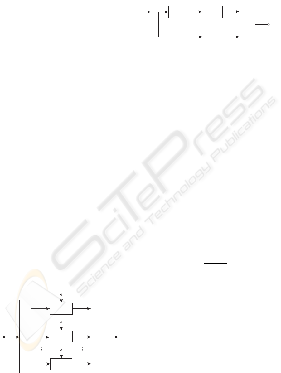
encoder
∏
Mapper
Mapper
Mapper
˜
b
1,k
˜
b
2,k
˜
b
L,k
MUX and Buffer
Figure 1: The channel-encoded MIMO transmitter’s struc-
ture.
tivated MIMO layer is given by
P
(k)
BER
=
1
∑
L
ν=1
log
2
(M
ν
)
L
∑
ℓ=1
log
2
(M
ℓ
)P
(ℓ,k)
BER
. (18)
Taking K consecutive time slots into account, needed
to transmit the SDM MIMO data vector, the aggre-
gate bit-error probability per SDM MIMO data vector
yields
P
BERblock
=
1
K
K
∑
k=1
P
(k)
BER
. (19)
When considering time-variant channel conditions,
rather than an AWGN channel, the BER can be de-
rived by considering the different transmission block
SNRs. Assuming that the transmit power is uniformly
distributed over the number of activated MIMO lay-
ers, i.e., P
sℓ
= P
s
/L, the half-level transmit amplitude
U
sℓ
per activated MIMO layer results in
U
sℓ
=
s
3P
s
2L(M
ℓ
−1)
. (20)
Finally, the layer-specific signal-to-noise ratio at the
time k, defined in (14), results together with (20) in
ρ
(ℓ,k)
= ξ
ℓ,k
3
2L(M
ℓ
−1)
P
s
U
2
R
= ξ
ℓ,k
3
L(M
ℓ
−1)
E
s
N
0
, (21)
with
P
s
U
2
R
=
E
s
N
0
/2
. (22)
4 CODED MIMO SYSTEM
The transmitter structure including channel coding
is depicted in Figure 1. The encoder employs a
y
1,k
y
2,k
y
L,k
Soft Demapper
L
(ν)
2
(
˜
b)
∏
−1
∏
L
(ν)
a,1
(b)
decoder
L
(ν)
1
(i)
L
(ν)
1
(b)
L
(ν−1)
e,1
(b)
L
(ν)
a,2
(
˜
b)
Figure 2: Iterative demodulator structure.
half-rate nonrecursive, non-systematic (NSC) convo-
lutional code using the generatorpolynomials (7,5) in
octal notation. The uncoded information is organized
in blocks of N
i
bits, consisting of at least 3000 bits,
depending on the specific QAM constellation used.
Each data block i is encoded and results in the block
b consisting of N
b
= 2N
i
+ 4 encoded bits, includ-
ing 2 termination bits. The encoded bits are inter-
leaved using a random interleaver and stored in the
vector
˜
b. The encoded and interleaved bits are then
mapped to the MIMO layers. The task of the mul-
tiplexer and buffer block of Figure 1 is to divide the
vector of encoded and interleaved information bits
˜
b
into subvectors (
˜
b
1,k
,
˜
b
2,k
,··· ,
˜
b
L,k
), each consisting
of 8 bits according to the chosen transmission mode
(Table 1). The individual binary data vectors
˜
b
ℓ,k
are
then mapped to the QAM symbols c
ℓ,k
according to
the specific mapper used. The iterative demodulator
structure is shown in Figure 2 (Ahrens et al., 2008).
A detailed structure of the soft demapper structure is
portrayed in Figure 3. When using the iteration in-
dex ν, the first iteration of ν = 1 commences with
the soft-demapper delivering the N
b
log-likelihood
ratios (LLRs) L
(ν=1)
2
(
˜
b) of the encoded and inter-
leaved information bits, whose de-interleaved version
L
(ν=1)
a,1
(b) represents the input of the convolutionalde-
coder as depicted in Figure 2 (Bahl et al., 1974; K¨uhn,
2006). This channel decoder provides the estimates
L
(ν=1)
1
(i) of the original uncoded information bits as
well as the LLRs of the N
b
NSC-encoded bits in the
form of
L
(ν=1)
1
(b) = L
(ν=1)
a,1
(b) + L
(ν=1)
e,1
(b) . (23)
As seen in Figure 2 and (23), the LLRs of the
NSC-encoded bits consist of the receiver’s input sig-
nal itself plus the extrinsic information L
(ν=1)
e,1
(b),
which is generated by subtracting L
(ν=1)
a,1
(b) from
L
(ν=1)
1
(b). The appropriately ordered, i.e. inter-
leaved extrinsic LLRs are fed back as a priori in-
formation L
(ν=2)
a,2
(
˜
b) to the soft demapper of Fig-
ure 2 for the second iteration. Following the de-
tailed structure of the soft-demapper in Figure 3, the
N
b
LLRs L
(ν)
2
(
˜
b) are composed of the subvectors
(L
(ν)
2
(
˜
b
1,k
),L
(ν)
2
(
˜
b
2,k
),··· , L
(ν)
2
(
˜
b
L,k
)), each consist-
WINSYS 2009 - International Conference on Wireless Information Networks and Systems
76
ing of 8 elements according to the chosen transmis-
sion mode (Table 1). Each vector L
(ν)
2
(
˜
b
ℓ,k
) is gener-
ated by the soft demapper from the MIMO channel’s
output y
ℓ,k
and the a-priori information L
(ν)
a,2
(
˜
b
ℓ,k
) pro-
vided by the channel decoder. After the first iteration,
this a-priori information emerges from the N
b
LLRs
L
(ν)
a,2
(
˜
b), which are again decomposed into the subvec-
tors (L
(ν)
a,2
(
˜
b
1,k
),L
(ν)
a,2
(
˜
b
2,k
),··· , L
(ν)
a,2
(
˜
b
L,k
)), each con-
sisting of 8 elements.
5 EXIT TRANSFER FUNCTION
Random variables (r.v.s) are denoted with capital let-
ters and their corresponding realizations with lower
case letters. Sequences of random variables and re-
alizations are indicated by boldface italics letters (as
B or b ). Furthermore, boldface roman letters denote
vectors (as B or b). The time instant is denoted with k
and the layer with ℓ. The transmitted data sequence B
is multiplexed onto the different used MIMO layers ℓ
and results in the MIMO layer specific sequence B
ℓ
with ℓ = 1, 2,. ..,L. The stationary binary input se-
quence B
ℓ
= [B
ℓ,1
,B
ℓ,2
,... ,B
ℓ,k
,... ] consists of r.v.s
B
ℓ,k
, where the corresponding realizations b
ℓ,k
have
an index length of 1 bit and are taken from a finite
alphabet B = {0,1}. The mapper output sequence
C
ℓ
= [C
ℓ,1
,C
ℓ,2
,... ,C
ℓ,k
,... ] on the ℓ-th layer consists
of r.v.s C
ℓ,k
, where the corresponding realizations c
ℓ,k
have an index length of log
2
(M
ℓ
) bits and are taken
from a finite alphabet C = {0,1, ..., M
ℓ
−1}. The
symbols c
ℓ,k
are transmitted over independent chan-
nels resulting in the received values y
ℓ,k
. The a priori
channel, as depicted in Figure 4, models the a priori
information used at the soft demapper. The sequence
A
ℓ
= [A
ℓ,1
,A
ℓ,2
,... ,A
ℓ,k
,... ] with the corresponding
realizations a
ℓ,k
contains the a priori LLR informa-
tion passed to the demapper. EXIT charts visualize
y
1,k
y
2,k
y
L,k
Soft-
Soft-
Soft-
Demapper
Demapper
Demapper
L
(ν)
2
(
˜
b
1,k
)
L
(ν)
2
(
˜
b
2,k
)
L
(ν)
2
(
˜
b
L,k
)
L
(ν)
a,2
(
˜
b
1,k
)
L
(ν)
a,2
(
˜
b
2,k
)
L
(ν)
a,2
(
˜
b
L,k
)
L
(ν)
2
(
˜
b)
L
(ν)
a,2
(
˜
b)
DEMUX and Buffer
MUX and Buffer
Figure 3: Detailed soft demapper demodulator structure.
b
ℓ,k
c
ℓ,k
y
ℓ,k
a
ℓ,k
e
ℓ,k
Mapper
Comm.
channel
A Priori
channel
Soft Demapper
Figure 4: Transmission model analyzing the ℓ-th MIMO
layer.
the input/output characteristics of the soft demap-
per and the decoder in terms of a mutual informa-
tion transfer between the data sequence B
ℓ
and the
sequence A
ℓ
of the a priori LLR information at the
input of the soft demapper, as well as between B
ℓ
and
the sequence E
ℓ
of the extrinsic LLR at the output, re-
spectively. Denoting the mutual information between
two r.v.s X and Y as I(X;Y) we may define for a given
sequence B
ℓ
the quantities I
ℓ,A
= I(A
ℓ
;B
ℓ
) as well
as I
ℓ,E
= I(E
ℓ
;B
ℓ
). Herein, I
ℓ,A
represents the aver-
age a priori information and I
ℓ,E
the average extrinsic
information, respectively (Ahrens et al., 2008). The
transfer characteristic T of the soft demapper is given
by I
ℓ,E
= T(I
ℓ,A
,ρ), where ρ represents the SNR of
the communication channel. Analyzing the outer de-
coder in a serially concatenated scheme T does not
depend on ρ. An EXIT chart is now obtained by plot-
ting the transfer characteristics T for both the demap-
per and the decoder within a single diagram, where
the axes have to be swapped for one of the constituent
decoders (Brink, 2001) (normally the outer one for
serial concatenation).
Analyzing the layer specific characteristics, a
MIMO-layer specific parameter α
(ℓ)
can be defined
according to
α
(ℓ)
=
log
2
(M
ℓ
)
R
, (24)
describing the fraction of the data sequence B that is
transmitted over the ℓth layer, i. e. B
ℓ
(Ahrens et al.,
2008). Therein, the parameter R describes the num-
ber of transmitted bits per time interval including all
L MIMO layers and results in R =
∑
L
ℓ=1
log
2
(M
ℓ
).
Hence, the mutual information for a given sequence
B and the extrinsic LLR E at the output is obtained
by
I(E ;B ) =
L
∑
ℓ=1
α
(ℓ)
I(E
ℓ
;B
ℓ
) . (25)
The MIMO layer specific extrinsic LLR sequences
E
ℓ
are multiplexed onto the sequence E , which is
lead to the outer decoder (Ahrens et al., 2008). Ben-
eficial values of α
(ℓ)
may be chosen by ensuring that
there is an open EXIT tunnel between the soft demap-
per transfer characteristic and the decoder transfer
MODULATION-MODE ASSIGNMENT IN SVD-ASSISTED BROADBAND MIMO-BICM SCHEMES
77
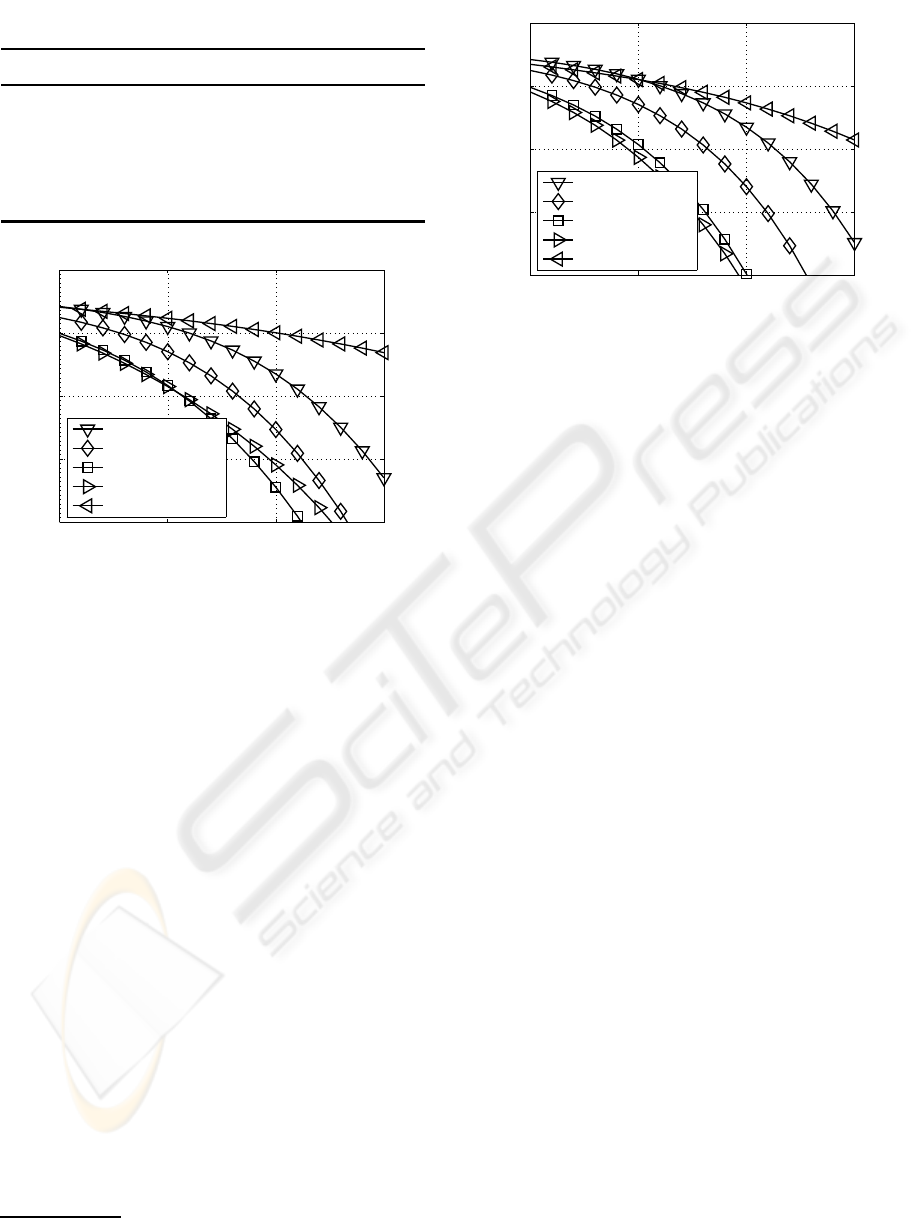
Table 2: Transmission modes and corresponding α
(ℓ)
.
M
1
,α
(1)
M
2
,α
(2)
M
3
,α
(3)
M
4
,α
4)
8 bit/s/Hz 256, 1 0,0 0,0 0,0
8 bit/s/Hz 64, 3/4 4,1/4 0,0 0,0
8 bit/s/Hz 16,1/2 16, 1/2 0,0 0,0
8 bit/s/Hz 16,1/2 4,1/4 4,1/4 0,0
8 bit/s/Hz 4,1/4 4,1/4 4,1/4 4,1/4
10 15 20 25
10
−8
10
−6
10
−4
10
−2
10
0
10 ·lg(E
s
/N
0
) (in dB) →
bit-error rate →
(256,0,0, 0) QAM
(64,4,0, 0) QAM
(16,16,0, 0) QAM
(16,4,4, 0) QAM
(4,4, 4,4) QAM
Figure 5: BER when using the transmission modes intro-
duced in Table 1 and transmitting 8 bit/s/Hz over frequency
selective channels with L
c
= 1.
characteristic at a given E
s
/N
0
value that is close to
the channel capacity bound. Analyzing the transmis-
sion modes in Table 1, the resulting values of α
(ℓ)
are
shown in Table 2.
6 RESULTS
In this contributionfixed transmission modes are used
regardless of the channel quality. Assuming prede-
fined transmission modes, a fixed data rate can be
guaranteed. The obtained uncoded BER curves are
depicted in Figure 5 and 6 for the different QAM
constellation sizes and MIMO configurations of Ta-
ble 1, when transmitting at a bandwidth efficiency of
8 bit/s/Hz
3
. Assuming a uniform distribution of the
transmit power over the number of activated MIMO
layers, it turns out that not all MIMO layers have to
be activated in order to achieve the best BERs. More
explicitly, our goal is to find that specific combination
of the QAM mode and the number of MIMO layers,
which gives the best possible BER performance at a
3
The expression lg(·) is considered to be the short form
of log
10
(·).
10 15 20 25
10
−8
10
−6
10
−4
10
−2
10
0
10 ·lg(E
s
/N
0
) (in dB) →
bit-error rate →
(256,0,0, 0) QAM
(64,4,0, 0) QAM
(16,16,0, 0) QAM
(16,4,4, 0) QAM
(4,4, 4,4) QAM
Figure 6: BER when using the transmission modes intro-
duced in Table 1 and transmitting 8 bit/s/Hz over frequency
selective channels with L
c
= 4.
given fixed bit/s/Hz bandwidth efficiency. However,
the lowest BERs can only be achieved by using bit
auction procedures leading to a high signalling over-
head. Analyzing the probability of choosing specific
transmission modes by using optimal bitloading as il-
lustrated in (Ahrens and Benavente-Peces, 2009) it
turns out that at moderate SNR only an appropriate
number of MIMO layers have to be activated, e. g.,
the (16,4, 4,0) QAM configuration.
Using the half-rate constraint-length K
cl
= 3 NSC
code, the BER performance is analyzed for an effec-
tive user throughput of 4 bit/s/Hz. The BER inves-
tigations using the NSC code are based on the best
uncoded schemes of Table 1. The information word
length is 3000 bits and a random interleaver is ap-
plied. In addition to the number of bits per symbol
and the number of activated MIMO layers, the achiev-
able performance of the iterative decoder is substan-
tially affected by the specific mapping of the bits to
both the QAM symbols as well as to the MIMO lay-
ers.
While the employment of the classic Gray-
mapping is appropriate in the absence of a priori
information, the availability of a priori information
in iterative receivers requires an exhaustive search
for finding the best non-Gray – synonymously also
referred to as anti-Gray – mapping scheme (Chin-
dapol, 2001). A mapping scheme optimized for per-
fect a priori information has usually a poor perfor-
mance, when there is no a priori information. How-
ever, when applying iterative demapping and decod-
ing, large gains can be achieved as long as the reli-
ability of the a priori information increases with the
number of iterations.
Analyzing the number of activated MIMO layers,
the soft-demappertransfer characteristics are depicted
in Figure 7 and 8 using anti-Gray mapping on all acti-
WINSYS 2009 - International Conference on Wireless Information Networks and Systems
78
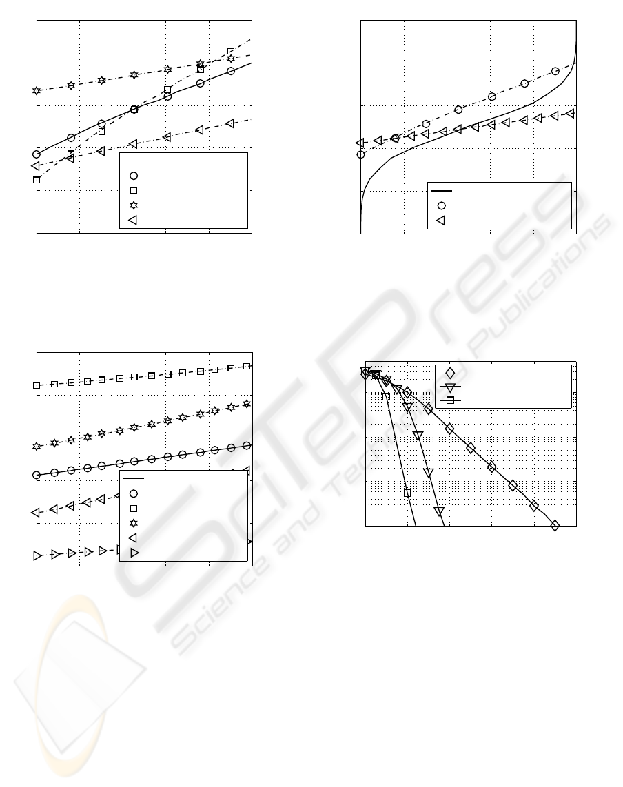
0 0.2 0.4 0.6 0.8 1
0
0.2
0.4
0.6
0.8
1
extrinsic demapper output →
a-priori input →
I(E ;B ), Equa. (25)
I(E
1
;B
1
), anti-Gray
I(E
2
;B
2
), anti-Gray
I(E
3
;B
3
), anti-Gray
I(E ;B ), Simulation
Figure 7: Layer-specific transfer characteristic when using
anti-Gray mapping and the (16,4,4,0) transmission mode
over frequency-selective MIMO links (10 log
10
(E
s
/N
0
) = 2
dB, L
c
= 1).
0 0.2 0.4 0.6 0.8 1
0
0.2
0.4
0.6
0.8
1
extrinsic demapper output →
a-priori input →
I(E ;B ), Equa. (25)
I(E
1
;B
1
), anti-Gray
I(E
2
;B
2
), anti-Gray
I(E
3
;B
3
), anti-Gray
I(E
4
;B
4
), anti-Gray
I(E ;B ), Simulation
Figure 8: Layer-specific transfer characteristic when using
anti-Gray mapping and the (4,4,4, 4) transmission mode
over frequency-selective MIMO links (10 log
10
(E
s
/N
0
) = 2
dB, L
c
= 1).
vated MIMO layers. Assuming predefined QAM con-
stellation sizes, the entire soft demapper transfer char-
acteristic is well predictable by combining the single
MIMO layer transfer characteristics using the param-
eter α
(ℓ)
. Using predefined QAM constellation sizes
and the corresponding α
(ℓ)
, the resulting EXIT chart
curve is depicted in Figure 9. In order to match the
soft demapper transfer characteristic properly to the
decoder transfer characteristic, a joint optimization of
the number of activated MIMO layers as well as the
number of bit per symbol has been carried out. Our
results suggest that not all MIMO layers have to be
0 0.2 0.4 0.6 0.8 1
0
0.2
0.4
0.6
0.8
1
extrinsic demapper output →
extrinsic decoder output →
NSC code
(16,4,4,0) QAM
(4,4,4,4) QAM
Figure 9: EXIT chart for an effective throughput of 4
bit/s/Hz when using anti-Gray mapping on all activated
MIMO layers (10 log
10
(E
s
/N
0
) = 2 dB and L
c
= 1) and the
half-rate NSC code with the generator polynomials of (7, 5)
in octal notation.
0 2 4 6 8 10
10
−4
10
−3
10
−2
10
−1
10 ·lg(E
s
/N
0
) (in dB) →
bit-error rate →
(4,4, 4,4) QAM, 3 Iter.
(16,4, 4,0) QAM, 3 Iter.
(16,4, 4,0) QAM, 10 Iter.
Figure 10: BER for an effective user throughput of 4
bit/s/Hz (L
c
= 1) and anti-Gray mapping in combination
with different transmission modes and the half-rate NSC
code with the generator polynomials of (7,5) in octal no-
tation.
activated in order to shape the soft demapper transfer
characteristic properly. The best uncoded solutions
seems also to be useful in the coded scenario. The
corresponding BER curves are shown in Figure 10
and confirm the EXIT charts results. In order to guar-
antee an efficient information exchange between the
soft-dempapper and the decoder, i. e., an open EXIT
tunnel, only an appropriate number of MIMO layers
has to be activated. Using all MIMO layers for the
data transmission, the information exchange between
the soft-dempapper and the decoder stops relatively
early, as illustrated by the EXIT chart results in Fig-
ure 9, and significant enhancements in the BER per-
formance can’t be achieved any longer by increasing
MODULATION-MODE ASSIGNMENT IN SVD-ASSISTED BROADBAND MIMO-BICM SCHEMES
79

the number of iterations at low SNR. As demonstrated
along this work, it is showed that an appropriate num-
ber of MIMO layers seems to be a promising solution
for minimizing the overall BER characteristic.
7 CONCLUSIONS
The choice of the number of bits per symbol and the
number of MIMO layers combined with error cor-
recting codes substantially affects the performance of
a MIMO system. Analyzing the uncoded system, it
turns out that not all MIMO layers have to be acti-
vated in order to achieve the best BERs. Considering
the coded system, the choice of the mapping strate-
gies combined with the appropriate number of acti-
vated MIMO layers and transmitted bits per symbol
offers a certain degree of design freedom, which sub-
stantially affects the performance of MIMO systems.
Here, using an appropriate number of MIMO layers
for the data transmission seems to be a promising so-
lution for minimizing the overall BER characteristic.
REFERENCES
Ahrens, A. and Benavente-Peces, C. (2009). Modulation-
Mode and Power Assignment in SVD-assisted Broad-
band MIMO Systems. In International Conference
on Wireless Information Networks and Systems (WIN-
SYS), Milan (Italy).
Ahrens, A. and Lange, C. (2008). Modulation-Mode and
Power Assignment in SVD-equalized MIMO Sys-
tems. Facta Universitatis (Series Electronics and En-
ergetics), 21(2):167–181.
Ahrens, A., Ng, S. X., K¨uhn, V., and Hanzo, L. (2008).
Modulation-Mode Assignment for SVD-Aided and
BICM-Assisted Spatial Division Multiplexing. Phys-
ical Communications (PHYCOM), 1(1):60–66.
Bahl, L. R., Cocke, J., Jelinek, F., and Raviv, J. (1974).
Optimal Decoding of Linear Codes for Minimizing
Symbol Error Rate. IEEE Transactions on Informa-
tion Theory, 20(3):284–287.
Brink, S. t. (2001). Convergence Behavior of Iteratively
Decoded Parallel Concatenated Codes. IEEE Trans-
actions on Communications, 49(10):1727–1737.
Caire, G., Taricco, G., and Biglieri, E. (1998). Bit-
Interleaved Coded Modulation. IEEE Transactions on
Information Theory, 44(3):927–946.
Chindapol, A. Ritcey, J. A. (2001). Design, Analysis, and
Performance Evaluation for BICM-ID with square
QAM Constellations in Rayleigh Fading Channels.
IEEE Journal on Selected Areas in Communications,
19(5):944–957.
Hanzo, L. and Keller, T. (2006). OFDM and MC-CDMA.
Wiley, New York.
Haykin, S. S. (2002). Adaptive Filter Theory. Prentice Hall,
New Jersey.
K¨uhn, V. (2006). Wireless Communications over MIMO
Channels – Applications to CDMA and Multiple An-
tenna Systems. Wiley, Chichester.
McKay, M. R. and Collings, I. B. (2005). Capacity
and Performance of MIMO-BICM with Zero-Forcing
Receivers. IEEE Transactions on Communications,
53(1):74– 83.
Mueller-Weinfurtner, S. H. (2002). Coding Approaches for
Multiple Antenna Transmission in Fast Fading and
OFDM. IEEE Transactions on Signal Processing,
50(10):2442–2450.
Proakis, J. G. (2000). Digital Communications. McGraw-
Hill, Boston.
Raleigh, G. G. and Cioffi, J. M. (1998). Spatio-Temporal
Coding for Wirless Communication. IEEE Transac-
tions on Communications, 46(3):357–366.
Raleigh, G. G. and Jones, V. K. (1999). Multivariate
Modulation and Coding for Wireless Communication.
IEEE Journal on Selected Areas in Communications,
17(5):851–866.
Schreckenbach, F. and Bauch, G. (2006). Bit-Interleaved
Coded Irregular Modulation. European Transactions
on Telecommunications, 17(2):269–282.
Wong, C. Y., Cheng, R. S., Letaief, K. B., and Murch, R. D.
(1999). Multiuser OFDM with Adaptive Subcarrier,
Bit, and Power Allocation. IEEE Journal on Selected
Areas in Communications, 17(10):1747–1758.
Zheng, L. and Tse, D. N. T. (2003). Diversity and
Multiplexing: A Fundamental Tradeoff in Multiple-
Antenna Channels. IEEE Transactions on Information
Theory, 49(5):1073–1096.
Zhou, Z., Vucetic, B., Dohler, M., and Li, Y. (2005). MIMO
Systems with Adaptive Modulation. IEEE Transac-
tions on Vehicular Technology, 54(5):1073–1096.
WINSYS 2009 - International Conference on Wireless Information Networks and Systems
80
