
MODEL-DRIVEN DEVELOPMENT IN INDUSTRIAL
AUTOMATION
Automating the Development of Industrial Automation Systems using
Model Transformations
Mathias Maurmaier and Peter Göhner
Institute of Industrial Automation and Software Engineering, Universität Stuttgart
Pfaffenwaldring 47, 70550 Stuttgart, Germany
Keywords: Model-driven Development, MDE, Model Transformation, Domain-specific Modeling Language, Industrial
Automation Systems.
Abstract: The complexity of modern automation systems is growing steadily. In software engineering, model-driven
development proved that it contributes significantly to cope with this complexity in development, while
increasing efficiency and the quality of the development results. However, hardware-software dependencies,
different types of requirements that must be considered in development and the large number of modeling
languages are specific challenges for a model-driven approach in automation technology. In this paper a
concept of model-driven system development is presented that takes into account these challenges, and thus
provides the possibility to leverage model-driven development in industrial automation technology.
1 INTRODUCTION
Because of the integration of new functions and
technologies necessary to fulfill customer require-
ments, environmental regulations or safety stan-
dards, the complexity of automation systems
increases steadily (Ramebäck, 2003). Therefore,
adequate development methods are needed pro-
viding the means to increase efficiency in develop-
ment and to increase the quality of the development
results. In software engineering, model-driven deve-
lopment has proven that it offers mechanisms to
cope with the increasing complexity and to boost
efficiency in development (Schmidt, 2006).
In this paper we analyze, why model-driven
development is rarely used for the development of
industrial automation systems and present a concept
based on extended model transformations that
allows to benefit from the advantages of model-
driven development in industrial automation
technology. Therefore we discuss specific challen-
ges in development of industrial automation systems
in chapter 2. Starting with a theoretical consideration
of system development and the theory of model-
driven development in chapter 3, the limiting factors
regarding the application for automation systems
development are presented in chapter 4. Based on
the limitations a concept of model-driven develop-
ment for industrial automation systems is deducted.
2 CHALLENGES IN
INDUSTRIAL AUTOMATION
Industrial automation systems are complex hard-
ware-software systems, whose objective is the con-
trol and supervision of a technical process. Many
different disciplines as software engineering,
hardware development, or electrical engineering are
involved in the development of such systems.
Modeling is seen as an important lever for coping
with the complexity in, since any model allows to
focus on specific aspects. Therefore, for system
development, many different models are used. Since
dependencies between the various models are not
automatically managed, there is a high manual effort
for multiple entries of the same information and for
ensuring consistency of the models (Schenk and
Schlereth, 2008). Therefore, we need concepts to
manage the dependencies between the various
models used during development.
244
Maurmaier M. and Göhner P. (2009).
MODEL-DRIVEN DEVELOPMENT IN INDUSTRIAL AUTOMATION - Automating the Development of Industrial Automation Systems using Model
Transformations.
In Proceedings of the 6th International Conference on Informatics in Control, Automation and Robotics - Robotics and Automation, pages 244-249
DOI: 10.5220/0002209502440249
Copyright
c
SciTePress
In contrast to software engineering, there is no
established, universal modeling language such as the
UML in industrial automation technology. This is
due to the various disciplines involved in develop-
ment, using specific modeling languages tailored to
their needs. Thus, the development method must be
open to the use of different modeling languages.
The hardware of an industrial automation system
consisting of sensors, actuators and processing units,
and the software are highly integrated, leading to a
large number of dependencies in development. In
order to increase efficiency and the quality of the
developed industrial automation systems, reusable
partial solutions should be used whenever possible.
These partial solutions consist both of hardware
parts and a specification or implementation of the
related software parts. Hence, the development
method for industrial automation systems must pro-
vide reusable partial solutions and has to offer con-
cepts to manage hardware-software dependencies.
In the development of an industrial automation
system different types of requirements must be
fulfilled. First of all, the technical process needs to
be controlled and monitored. Further specific re-
quirements for the automation system arise from the
realization of the technical system, from existing
legacy systems as well as from legal and economic
constraints. These requirements can demand a
specific property of the overall automation system as
for example reduced energy consumption or a
property of an individual subsystem, e.g. the manu-
facturer of a specific subsystem or a specific bus-
system to be used. These requirements vary between
different automation systems that realize the same
technical process. Any development method in
industrial automation technology must support these
different kinds of requirements.
3 SYSTEMS DEVELOPMENT
3.1 Basic Definitions
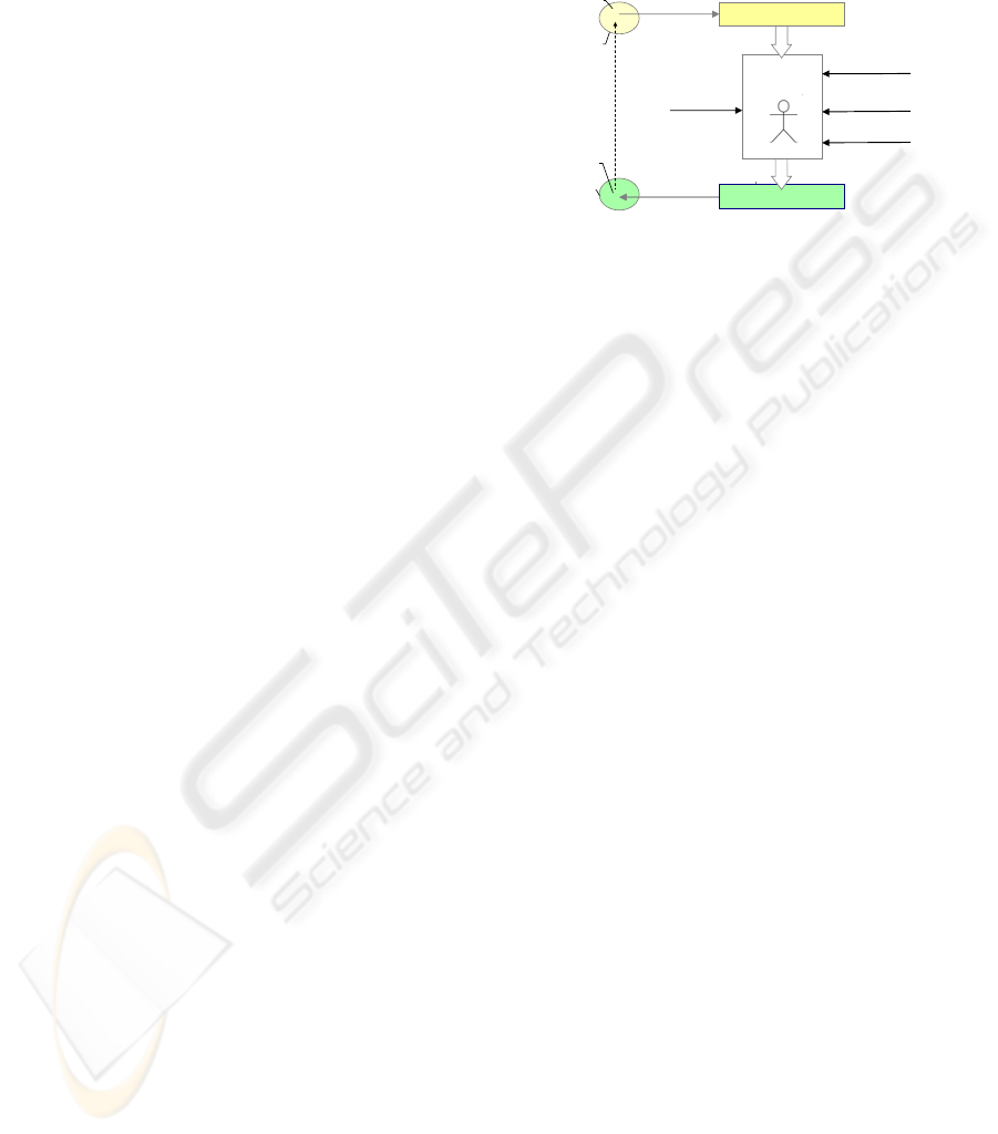
According to Smith and Browne (1993) develop-
ment is the creation of a system or artifact to solve a
given problem. Therefore representations of the real
world are used. In the representation of the problem
R(P) the problem is described using the vocabulary,
concepts and metrics of the problem space. Starting
from this representation the representation of the
solution R(L) is developed in several development
steps. Based on the representation of the solution
R(L), the system can be produced. There may be
representations of different formalization degrees. A
textual requirements specification, for example, is an
informal representation of the problem to be solved;
the source code of the automation software is a
formal representation of the solution.
implementation
representation R(L)
x
solution L
solution
space
x
problem P
problem
space
production
developers‘
know-how
technology
required
system properties
design
decisions
partial
solutions
representation R(P)
documentation
Figure 1: Systems development.
The system to be developed consists of a set of
individual elements, which are related to each other
and interact in a way, that they fulfill a common goal
(Sommerville, 2007). The elements can be atomic or
subsystems, i.e. in this case they are systems as well.
The system properties comprise both the properties
of the individual elements, e.g. the manufacturer of
the element or subsystem, and the properties that
arise from the interplay of the elements as for
example energy consumption or reliability. The
latter are known as global system properties.
Considering the requirements to be fulfilled by a
system, they can focus on different aspects: First of
all, there are requirements describing the problem to
be solved by the system. Other requirements focus
on the global properties, the system must prove.
Examples for this class are requirements concerning
energy consumption. A third class of requirements
prescribes properties of individual elements. These
latter two classes of requirements restrict the number
of possible solutions of the problem.
During development, a multitude of design
decisions have to be made, which affect the solution.
These decisions are made by the engineer combining
his own knowledge and expertise with the required
system properties, available technologies and
reusable partial solutions. In decision-making the
engineer has to consider all interdependencies
between the technologies and partial solutions. If
there is a modification in the problem to be solved,
in required system properties or in the partial
solutions, all decisions must be checked manually
for correctness under the new circumstances.
The aim of model-driven development is to auto-
matically generate the representation of the solution
R(L) from the representation of the problem R(P).
Therefore the basics of model-driven development
are described in the following section.
MODEL-DRIVEN DEVELOPMENT IN INDUSTRIAL AUTOMATION - Automating the Development of Industrial
Automation Systems using Model Transformations
245
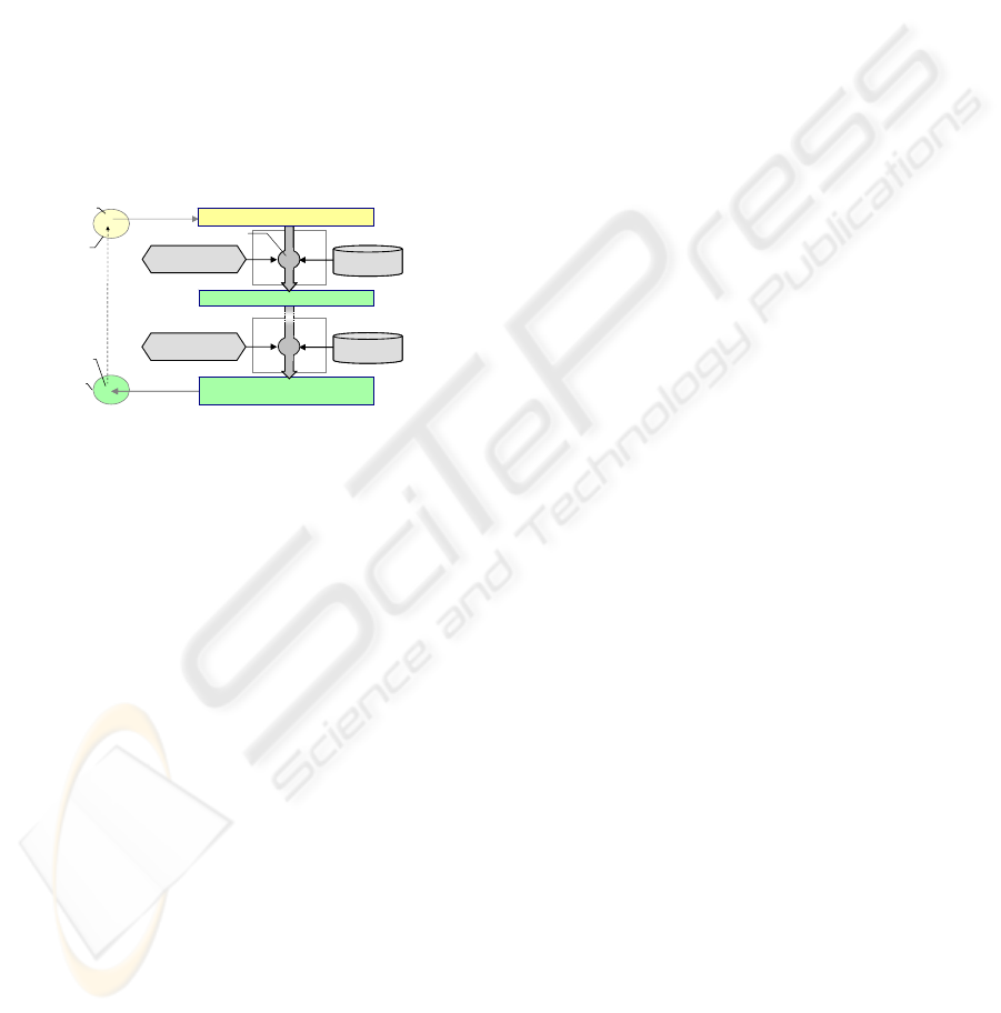
3.2 Model-driven Development
In model-driven development, the course of the
development from problem analyses to design and
implementation is defined by models (OMG, 2003),
whereas a model is a formalized representation of
some aspects of the problem to be solved or the
system to be developed. The formalized represen-
tation of the problem is called conceptual model
M(P). This model has a high level of abstraction. As
shown in figure 2, transformations are used for the
automated generation of the model of the solution
M(L) out of the conceptual model M(P). A trans-
formation is the conversion of a source model into a
target model based on a formalized specification. As
prerequisite for an automated transformation, all
factors affecting the solution must be formalized.
production
x
x
problem P
problem
space
transformation
rules 1
platform 1platform 1
platform nplatform n
model of solution M(L) =
target model of transformation n
target model of transformation 1
transformation
transformation
rules n
conceptual model M(P)
solution L
solution
space
modeling
implementation
Figure 2: Model-driven systems development.
To implement a transformation, a platform and
transformation rules are needed. The platform con-
tains all available reusable partial solutions of one
dedicated level of abstraction, whose interfaces and
properties are described in a formalized way.
The platforms used in the various transforma-
tions determine much of the system properties. In
reverse requirements concerning system properties
such as high reliability or the operating system to be
used determine the platforms to be chosen for the
development of the system.
Transformation rules formalize the part of the
developer’s knowledge needed for the selection,
linkage and configuration of the partial solutions of
the platform, which are needed to implement the
problems that can be modeled in the source model.
When executing a transformation, the transformation
rules link the problem modeled in the source model
with the partial solutions of the platform.
Since the transformation rules link the model
elements of the source model with the partial solu-
tions of the platform, they depend on the modeling
language of the source model and the description of
the partial solutions. This is why standards for the
specification of transformation rules such as QVT
(OMG, 2008) define the structure of the rules using
metamodels. These standards are very generic and
require high efforts to define the necessary trans-
formation rules when introducing model-driven
development in a specific domain. Hence, currently
transformations are usually realized for specific
modeling languages and platforms within integrated
development environments. Since in software engi-
neering there are standard modeling languages as for
example the UML or signal flow diagrams, model-
driven development techniques are applied especial-
ly in application domains in software engineering
that traditionally use these modeling languages.
The identification of the necessary transforma-
tions and the modeling languages used within a
domain as well as the development of platforms and
transformation rules takes place in a preceding,
project-independent development phase, called
infrastructure development. In this phase, domain
engineering activities are executed in order to
develop the artifacts, which will be reused within
various projects later in the system development
phase. In the system development phase, the
platforms and transformation rules are reused.
In model-driven development dependencies
between different views and partial solutions are
used to define transformations allowing an
automated generation of more detailed models, or
source code from other usually more abstract
models. In the following chapter, we discuss the
limitations of the current transformation concepts
regarding the application for the development of
industrial automation systems and propose concepts
allowing to leverage the advantages of model-driven
development in industrial automation technology.
4 MODEL-DRIVEN
DEVELOPMENT OF
AUTOMATION SYSTEMS
4.1 Model-driven Development and
Challenges of Industrial
Automation Technology
In model-driven development platforms are used to
manage reusable partial solutions, which are
described in a formalized way and stored in a clear
structure within the platforms. Partial solutions
consisting of hardware-software parts, as needed in
automation technology, are not supported by
existing model-driven approaches. Therefore, an
extension of the classical model-driven development
approach is needed to support partial solutions with
ICINCO 2009 - 6th International Conference on Informatics in Control, Automation and Robotics
246
hardware and software parts and to be able to
manage hardware-software dependencies.
In classical model-driven development, the
solution is built based on the conceptual model M(P)
and the selected platforms. Platforms and trans-
formation rules are not adaptable in system develop-
ment. Hence, besides the conceptual model M(P)
and the selection of the platforms, there are no
further possibilities to influence the solution in the
system development phase. Requirements con-
cerning system properties can only be fulfilled, if
there is a platform, which has exactly the required
properties. As in automation technology there are a
lot of requirements focusing on system properties,
we would need an enormous number of platforms
for any combination of required system properties.
As this is not feasible in practice, we propose an
extension of the classical model-driven development
approach allowing to specify required system
properties and thus to influence the solution.
Existing implementations of transformations
cannot be used in automation technology due to the
variety of modeling languages and the close hard-
ware-software dependencies. To reduce the efforts in
infrastructure development and to make the concept
applicable to engineers, the generic concepts for the
definition of transformation rules must be
concretized. Standards as AutomationML (Drath et
al., 2008) define metamodels for the description of
automation technical solutions. As engineers are
getting familiar with these standards, the description
of the platform elements is based on these standards.
The integration of these approaches into a
concept for hardware-software integration is
described in the following paragraph in more detail.
4.2 Platforms for Hardware-Software
Integration
In industrial automation technology, reusable partial
solutions are composed of hardware and software
parts. On the level of models, this means that the use
of a partial solution has an impact both on hardware
models (e. g. circuit diagram) and on software
models such as source code. One partial solution has
representations in several models. In order to
integrate the representations belonging to one partial
solution the concept of platforms is extended by
views. The platform for model-driven development
in automation technology consists not only of
software components but integrates partial
automation technical solutions of one abstraction
level. An automation technical partial solution is
created by the encapsulation of the representations
of the partial solution for the hardware and the soft-
ware models and a general description. For example,
the partial solution representing a speed sensor is
composed of a representation for the circuit diagram,
for the simulation model and a software driver.
software model hardware model
source model
sensor simulation
model
sensor-
software
component
sensor-
software
component
automation-tech-
nical partial
solution
platformplatform
transformation
rules
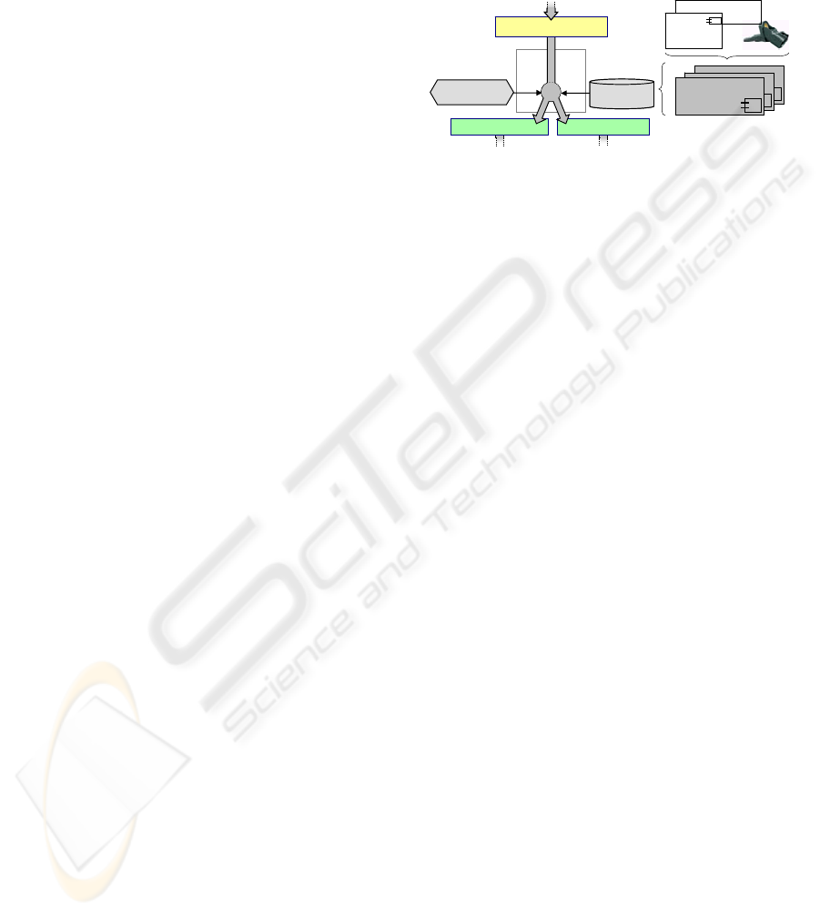
Figure 3: Transformation generating the hardware and
software model.
All automation technical partial solutions of one
abstraction level are merged into one platform. If,
during the execution of a transformation, a partial
solution is selected by a transformation rule, the
corresponding representation of the partial solution
is instantiated in any model generated by the
transformation. Figure 3 illustrates the course of a
transformation, which generates several target
models from one source model.
4.2.1 Unified Metamodel of Automation
Technical Partial Solutions
The knowledge, which partial solution should be
selected during the execution of a transformation,
how it must be connected and configured, is
encapsulated in the transformation rules. The
selection, linkage and configuration dependent on
many parameters. The required properties of a
partial solution are extracted from the source model.
Then, the suitable partial solution is selected from
the platform. To avoid that for any combination of
required properties a new transformation rule must
be created, the properties of any partial solution are
subsumed within its formalized description. Thus
transformation rules can select partial solutions by a
set of required properties. This leads to a greatest
possible decoupling between the transformation
rules and the partial solutions allowing to add new
partial solutions to the platform without having to
modify the transformation rules. The description of
each partial solution follows the metamodel
presented in figure 4. Any partial solution disposes
of features that are either fixed (property), optional
(option) or can be configured (parameters).
The representations of a partial solution in
different types of target models are encapsulated in
the partial solution (target model representation).
MODEL-DRIVEN DEVELOPMENT IN INDUSTRIAL AUTOMATION - Automating the Development of Industrial
Automation Systems using Model Transformations
247
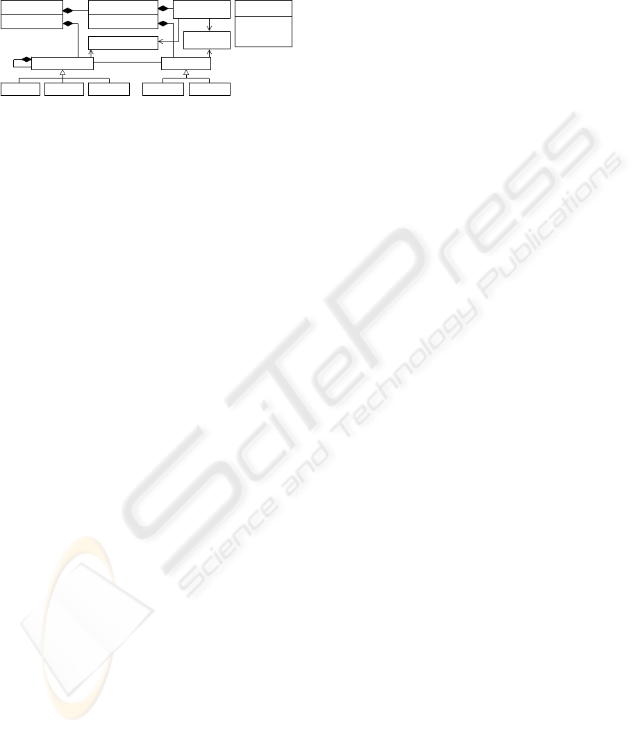
Each representation is assigned to a specific view
(View). A partial solution is linked with other partial
solutions using ports (Port).
Partial Solution
Name: String
Target model
representation
<<Enum>>
ViewType
General
Signal Flow
Circuit Diagram
Class Diagram
View
ViewType: ViewType
View
ViewType: ViewType
1..*
Property Option Parameter Outgoing Incoming
1..*
*
*
Feature Port
Configuration Rule
Consistency
Rule
Figure 4: Metamodel of an automation technical partial
solution within a platform.
Since dependencies between the hardware and
software parts of a partial solution are known best by
the developer of the partial solution, these can be
integrated as consistency rules. Configuration rules
adapt the representations within the different types
of target models to the actual configuration of the
partial solution. For example, if there is a parameter
allowing to adjust the value range of a sensor, the
configuration rules set the configuration values in
the source code of the driver and adjust the values of
the series resistor in the circuit diagram. When a
partial solution is selected, linked or configured
during the execution of a transformation, these rules
are evaluated. This allows automatic internal
adjustments of the partial solution to ensure
consistency between the different views.
4.2.2 Transformation Rules
One benefit of the unified metamodel of the partial
solutions within the platforms is the possibility to
define a general structure of the transformation rules
in automation technology. There are three major
types of transformation rules:
Transformation rules that encapsulate the know-
ledge to define the structure of the target model,
which allows solving the problem modeled in the
source model, are called structure-defining (SD)
rules. They extract the information from the source
model, which is relevant for the structure of the
target model, and create a possible structure of the
target model. In further steps, this structure has to be
detailed using partial solutions from the platform.
Selective (SL) transformation rules are used for
the selection of the correct partial solutions from the
platform. They encapsulate the knowledge about the
relevant properties, a partial solution needs to have
in order to be deployed in a certain position within
the structure of the target model. Selective
transformation rules define in a first step a complete
requirements specification for any position in the
structure of the target model that has to be detailed
by a partial solution. In the second step, the
requirements aggregated in the first step are used to
select the correct partial solution from the platform.
Transformation rules of the third type, called
configurational (CF) rules, ensure a consistent
configuration of the selected partial solutions within
all target models.
When a transformation is executed, the structure-
defining rules are applied first, followed by the
selective rules and in the end the configurational
rules. If a set of transformation rules produces
several possible solutions for a given source model,
there is the possibility to optimize the solution con-
cerning specific system properties.
Platforms and transformation rules are developed
in infrastructure development preceding the systems
development, where they are reused within many
systems. This allows increasing efficiency in de-
velopment and shortening the development time
within individual projects. Crucial disadvantages are
the high initial costs for the project-independent de-
velopment of transformation rules and platforms,
and the inflexibility regarding the consideration of
requirements concerning individual system pro-
perties in the transformations. A solution to this
problem is presented in the following section.
4.3 Adaptability of Transformations
In order to be able to specify the different kinds of
requirements and thus to fulfill them, the concept of
transformations of the classical model-driven
development is extended by two additional variation
points. These variation points can be used to modify
the solution. In analogy to framework theory, these
variation points are called hot spots of the
transformation. The first hot spot allows to adapt the
transformation rules to the requirements of a specific
project. This adaptation allows to model and thus to
respect required global system properties within the
transformation, i.e. properties that arise from the
interaction of the system elements. During the tool-
supported execution of the transformation different
architectural variants of the solution can be analyzed
in terms of meeting the required global system
properties. Finally, the one that meets best the
requirements is selected. For example, a reliable
temperature measurement can be realized using one
highly reliable sensor or a redundant measurement
with two or even more standard sensors. The
knowledge of the possible architectural variants and
the calculation of the reliability is formalized in the
transformation rules. Using the hot spot, these
ICINCO 2009 - 6th International Conference on Informatics in Control, Automation and Robotics
248

transformation rules are configured or even
completed by new rules formalizing the know-how
on the reliability that should be reached in the
current project, on possible architectural alternatives
and on their properties. The decision, which
alternative is best suited within the specific project,
is made during the execution of the transformation.
If the properties concerning reliability of the
available sensors are known, this decision for one
architectural variant can be made automatically
depending on the required reliability.
Required properties of individual system
elements such as the supplier of a specific partial
solution can be specified using the second hot spot.
This hot spot allows to access all properties of the
partial solutions of the platform and thus to select or
exclude specific partial solutions by any property.
The project-specific adaptation of the platform at
this hot spot prepares the set of partial solutions
from the platform, which may be used in the specific
development project.
Furthermore, the concept of hot spots allows
upgrading the transformation rules or the platform
within a development project. Thus, model-driven
development can be introduced iteratively, since the
missing transformation rules and partial solutions
can be added at the corresponding hot spot.
5 CONCLUSIONS
In model-driven development the course of
development is defined by models using the
principle of abstraction to focus only on the relevant
aspects in any development steps. Transformations
are used to transform the abstract models of the
problem to more detailed models of the solution.
The mature concepts of model-driven software
development can not be applied directly for the
development of automation systems, since they miss
concepts for the high variability concerning the
requirements on specific system properties and hard-
ware-software dependencies. Furthermore, a concept
for model-driven development in industrial auto-
mation technology must be adaptable to different
modeling languages as there are no standard
languages as for example the UML.
In this paper we presented a concept for model-
driven development of industrial automation
systems. Central aspects of this concept are
platforms built on automation technical partial
solutions, hot spots in the transformations and a
metamodel based definition of automation technical
partial solutions. The platforms allow reusing partial
solutions consisting of hardware and software parts.
Hardware-software dependencies are modeled by the
developer of the partial solution and are taken into
account when using a partial solution within a
transformation. Hot spots enable the developer to
adapt the transformation in order to fulfill
requirements concerning specific system properties.
The metamodel-based definition of the partial
solutions allows to reuse transformation rules and to
adapt them to different modeling languages.
The presented concept allows applying model-
driven development to the development of industrial
automation systems and leads to a better controlla-
bility of the complexity, increases efficiency and
shortens the development time within individual
industrial automation projects.
REFERENCES
Drath, R., Peschke, J., Lips, S. (2008). AutomationML
Top-level Architecture Document. AutomationML
consortium, Stuttgart.
International Organization for Standardization (1997).
Flow diagrams for process plants -- General rules.
ISO 10628:1997, Geneva: ISO.
Maurmaier, M. (2007). Model-driven system development
in product automation. In VDI-Bericht Nr. 1980 mit
CD 'GMA-Kongress 2007 Automation im gesamten
Lebenszyklus' ISBN 978-3-18-091980-5. VDI-Verlag,
Düsseldorf.
Maurmaier, M. (2008). Leveraging Model-driven
Development for Automation Systems Development.
In Proceedings of IEEE Conference on emerging
technologies and factory automation. Hamburg.
Object Management Group (2003). MDA Guide Version
1.0.1.
Object Management Group (2008). Meta Object Facility
(MOF) 2.0 Query/View/Transformation, Version 1.0.
Ramebäck, C. (2003). Process automation systems-history
and future. In Proceedings of IEEE Conference on
emerging technologies and factory automation.
Lisbon.
Schenk, B., Schlereth, M. (2008). Model Driven
Development applied to Automation Engineering. In
VDI-Bericht Nr. 2032 mit CD 'AUTOMATION 2008 -
Lösungen für die Zukunft' ISBN 978-3-18-092032-0.
VDI-Verlag, Düsseldorf.
Schmidt, D. (2006). Model-Driven Engineering. In: IEEE
Computer 39 (2), 25–31.
Smith, G., Brown, G. (1993). Conceptual Foundations of
Design Problem Solving. In IEEE Transactions on
Systems, Man, and Cybernetics; 23 (5), 1209-1219.
Sommerville, I (2007). Software Engineering. 8
th
ed.,
Pearson Education Limited, Harlow.
MODEL-DRIVEN DEVELOPMENT IN INDUSTRIAL AUTOMATION - Automating the Development of Industrial
Automation Systems using Model Transformations
249
