
APPLYING A SOFTWARE FRAMEWORK FOR SUPERVISORY
CONTROL OF A PLC-BASED DISCRETE EVENT SYSTEM
B. Curto, V. Moreno
Department of Informática y Automática, Salamanca University, Plaza de los Caídos, Salamanca, Spain
C. Fernández-Caramés, R. Alves, A. Chehayeb
Department of Informática y Automática, Salamanca University, Plaza de los Caídos, Salamanca, Spain
Keywords: Supervisory Control, Automated Manufacturing Systems, Software Framework, Discrete Event System.
Abstract: In this paper we propose a software framework where the main aim is to make easier the implementation of
supervisory control. The main idea is that functionalities must be offered with no effects on the robustness
of the system. We prove that our methodology has a solid base, so the approach can be applied to any kind
of industrial process unit. In this way, a real application of a developed framework is presented. The
implementation is done over well-known devices (such as PLC with a conveyor belt) so the technical
feasibility of the procedure is guaranteed.
1 INTRODUCTION
Due to the market evolution, manufacturing industry
suffers some pressures in order to reduce product
prices, to increase the model complexity and to
support a model proliferation (Beck, 2000). To
achieve these goals, it is necessary to accomplish
shorter production cycles and lower manufacturing
costs. More flexible and intelligent workcells are
needed in order to find a competitive manufacturing
process. Thus, as a part of a Computer Integrated
Manufacturing (CIM) goal, Flexible Manufacturing
Systems (FMS) offer the best promise of reducing
costs and increasing flexibility.
Current robotic workcell systems can generally
be classified as large, monolithic and centralized
systems. The main reason comes from the fact that,
in a typical industrial workcell, a Programmable
Logic Controller (PLC) acts as an operation
sequence controller of the cell. Several problems
arise with these systems: limited functionality and
flexibility, low levels of intelligence, and so on. As a
solution we will propose the use of a distributed
architecture design.
In (Curto, 2001), a proposal of a software
architecture is realized where the development of
distributed systems is taken into account. In a natural
way, the development of a framework is the next
step where some wrong situations appear when the
provided services at the system becomes blocked
due to an erroneous sequence of service invocations.
Thus, it is necessary to achieve that these blocked
situations will be avoided.
We propose the use of the Supervisory Control
Theory (SCT) (Ramadge, 1987) that is proposed
initially by P. J. Ramadge and W. M. Wonham in
the late 80s. This theory has received a special
attention from the academic environment in such a
way it has reached a great evolution. Nevertheless,
actually just a few applications at industrial
environment can be found that applies the SCT due
to mainly a complete model of the system (with a
sound mathematical load) and a corresponding
implementation is needed.
Although some works exist where the real
implementation of controller is obtained using the
SCT, they are not too much. Some of the most
representative are (Chandra, 2000) and (Mušić,
2002). The first one describes the way to design a
control system for assembling line whereas the
second one is focused on the implementation of a
concrete task on a PLC. In both cases, the controller
formally obtained using the SCT is restricted to
reach a particular goal at a concrete task.
This approach presents two main disadvantages.
First, if a modification of the task is made, it is
263
Curto B., Moreno V., Fernández-Caramés C., Alves R. and Chehayeb A. (2009).
APPLYING A SOFTWARE FRAMEWORK FOR SUPERVISORY CONTROL OF A PLC-BASED DISCRETE EVENT SYSTEM.
In Proceedings of the 6th International Conference on Informatics in Control, Automation and Robotics - Robotics and Automation, pages 262-267
DOI: 10.5220/0002211502620267
Copyright
c
SciTePress

necessary to perform the complete redesign and
implementation of the controller. Second, a unique
controller is not feasible when the task implies a
large set of sensors and actuators. In this situation,
the physical restrictions imposed by the
communications and a possible overload of the
controller are two questions that have to be taken
into account. Consequently, we propose to make a
separation between the particular device control and
the task to be performed at the plant.
In (Chandra, 2000), when the restriction of the
plant behaviour has to be done, two kinds of
specifications can be distinguished: security
specifications and progress specifications. The first
ones are considered to prevent that no plant section
takes undesirable actions and the second ones are
concerned to reach the finalization of the task.
Security specifications can affect to a unique plant
element or several elements.
In this work we propose to perform the controller
design for each device taking into account the
service that the component provides with no
consideration on the task that has to be done. The
key element will be the development and use of a
software framework where it will be necessary to
model and implement a set of specifications.
The rest of the paper is organized as follows: In
section 2 we review the Supervisory Control Theory.
Next, the main relevant topics of the proposed
architecture and the resulting framework will be
presented. In section 4, in order to prove the validity
of our proposal we will present a case of study
where a real industrial element will be considered.
Finally the main conclusions are presented.
2 MODELING DISCRETE EVENT
SYSTEMS
The SCT of Discrete Event Systems is based on the
use of automata and formal language models. Under
these models the main interest is on the order in
which the different events occur. In this way, a plant
(Phoha, 2004) is assumed to be the generator of
these events. The behaviour of the plant model is
described by event trajectories over the finite event
alphabet . These event trajectories can be thought
of as strings over , so represents the set of
those event strings that describe the behaviour of the
plant.
Σ
Σ
*
Σ⊆L
The SCT restricts the behaviour of a plant G by
disabling temporarily certain events that can be
created by
Σ , so the goal is that the plant cannot
create undesired or illegal event chains in L(G). In
the following, a few basic definitions will be posed.
The plant G will modelled by the deterministic
finite state automaton (DFSA)
),,,,,(
0 mGGG
XxfXG Γ
Σ
=
where,
X is the set of states;
G
Σ
is the finite set of events over
G
;
XXf
GG
→
Σ
×
:
is the state transition
function;
G
X
is the active event function;
G
Σ
→Γ 2:
Xx
∈
0
is the initial state;
XX
m
⊆
is the set of marked states, which
represent the completion of a certain task or a
set of tasks.
*
G
Σ
is used to denote the set of all finite length
strings over
G
Σ
including the empty string
ε
.
can be extended from to the
domain by means of recursion:
G
f
*
G
Σ
x
G
X Σ×
X ×
xf
G
=
),(
ε
,
)),,( esxff
G
( f
GG
),( sex
=
for , and
.
Xx∈
G
Σe∈
*
G
Σs ∈
The SCT distinguish between the controllable set
(
c
Σ
), which can be disabled, and the non-
controllable set (
nc
Σ
) which cannot be disabled. The
following relations are fulfilled: and
ncc
Σ∪Σ=Σ
∅
=
Σ
∩
Σ
ncc
.
In order to restrict the behaviour of the plant G,
one or more specifications can be defined, that are
usually modelled by a DFSA
),,,,,(
0 mHHH
YyfYH Γ
Σ
=
A restriction limits the behaviour of the plant by
means of one of the two composition operations
defined by the SCT. Informally, it can be said that a
composition operation allows two DFSA to run
synchronously, which means that certain events will
only be created if both DFSA are capable of doing
so. In this work we will consider (synchronous)
parallel composition of G and H, defined as:
)),,(,,,,(||
00|||| mmHGHGHG
YXyxfYXAcHG
×
Γ
Σ
∪
Σ
×
=
where
ICINCO 2009 - 6th International Conference on Informatics in Control, Automation and Robotics
264

⎪
⎪
⎩
⎪
⎪
⎨
⎧
Γ∈Σ∉
Σ∉Γ∈
Γ∩Γ∈
=
caseother definednot
)( and if)),(,(
and )( if)),,((
)()( if)),(),,((
)),,((
||
yeeeyfx
exeyexf
yxeeyfexf
eyxf
HGH
HGG
HGHG
HG
Γ
G
||
H
(
x
,y) =[Γ
G
(
x
)∩Γ
H
(y)]∪[Γ
G
(
x
) −Σ
H
]∪[Γ
H
(y)
−
Σ
G
]
Ac() denotes the accessible automaton part,
excluding thus the states which cannot be accessed
from x
0
state.
3 OVERVIEW OF DEVELOPED
FRAMEWORK
Traditionally, when changes in the production
process occur, the PLC that control the process need
to be reprogrammed as well. In order to get highly
flexible manufacturing systems, we propose a
framework with a core element: a service repository.
In this proposal, the services can be invoked
dynamically based on the production needs.
Therefore, if the production process is altered, then
the sequence of invocation of the services will be
modified. In this way, the main advantage is that the
software running on the PLC does not need any
modification at all, if all the required services have
been taken into account.
In our framework, if an input event e
i
is triggered
by an external entity for a certain service,
then ; if an internal event e
i
is created by the
plant, then . When certain services are
invoked, the system can stop working properly. In
order to avoid this, our proposal considers
supervising the behaviour of the system using SCT.
As stated in the previous section, once the plant G is
modelled, its behaviour is restricted by means of one
or more specifications H
k
that can temporarily
disable certain input events. Consequently, no
undesired actions will ever take place.
ci
e Σ∈
e
nci
Σ∈
Our framework (Figure 1) consists of the
following components:
Interface with external entities. Clients
invoke the services provided by the system
through this interface, and the
corresponding input event will be triggered.
Supervision: it is made up of a) the active
event function
Γ
of A, being
}
k
H
and b) the
synchronous composition
k
H
,
where the input events can be disabled if
needed.
{
HGA ∪∪∪= K
1
HG ||||||
1
K
State transition functions, which evolve in
accordance with 1) the input events that
have not been disabled previously in the
supervision and 2) the internal events of G.
In the plant, if an input event causes a
transition
G
f , it will activate the execution
of the corresponding service.
Services provided that gather a specified
functionality. Due to design criteria they are
isolated from the supervision role so it is
possible to perform modifications on the
functionality regarding supervision
consideration. This characteristic can be
seen as the main advantage.
In the following, the main behaviour will be
described. When an input event is triggered,
it is processed by the supervisor. The composition
operation, taking into account for each DFSA,
decides if e
i
must be disabled or not. If e
i
is enabled,
it is then processed by the f
A
of each DFSA,
including G. Therefore, if a transition is defined in
for e
i
and the current state of G, the
corresponding service will be run. Otherwise, if e
i
is
disabled, the transition does not happen, and the
requested service will never take place. As a result,
we make sure that the system behaves according to
its specifications at all times.
ci
e Σ∈
A
Γ
G
f
Figure 1: Global overview of the framework.
4 A CASE OF STUDY
In what follows we discuss how to use our proposed
framework in a typical element of a FSM cell: a
conveyor belt. We have chosen it because it is a
component found in every cell instance and because
the working specifications are changed frequently,
given that the conveyed elements must be moved to
APPLYING A SOFTWARE FRAMEWORK FOR SUPERVISORY CONTROL OF A PLC-BASED DISCRETE EVENT
SYSTEM
265

different target positions using different velocities as
well.
The plant is made up of a BOSCH conveyor belt
with encoder, dynamo and position sensors. The
control is carried out by the Allen Bradley SLC 500
series with the IMC 110 motion control module.
Depending on the operation mode of the IMC,
the conveyor belt can be moved manually or
automatically. Movements in manual mode are used
for initialization and maintenance by an operator and
are always executed at constant velocity.
Movements in automatic mode are performed when
some of the MML programs loaded in the IMC 110
memory is running, and it is possible to modify both
the velocity and the acceleration of the motion. In
order to work in automatic mode and know where
the tray is located it is needed to perform a home
operation. For security reasons, emergency stops
must be considered when in automatic mode.
Figure 2: Plant operation modelled by a DFSA G.
The DFSA G (Figure 2) models both the manual
and automatic mode of the conveyor belt. This plant
model DFSA is given as the 5-tuple with x
0
as initial
state. In the definition of the state set
(
{
70
,, xxX K=
}
Table 1) three factors have been
considered:
IMC operation mode (automatic or manual)
belt state (moving or not)
the presence of an emergency stop.
So, in this case, .
m
XX =
Respect to
Σ
(Table 2), the set
{
}
872
,, eee
NC
=Σ
{
654310
,,,,, eeeee
is generated from the information provided by the
IMC from sensors,
corresponds with the events provided by the system.
}
e
C
=Σ
The behaviour of the plant is controlled by two
restrictions:
R1) the movement to a target position (e
1
event) is not allowed prior to completing a
successful homing operation
R2) the change to automatic mode (e
4
event)
is not allowed prior to completing a
successful homing operation.
Table 1: G plant states.
State Mode Conveyor belt state e-stop
x
0
Manual Stopped Yes
x
1
Manual Stopped No
x
2
Manual Moving No
x
3
Automatic Stopped No
x
4
Automatic Moving Yes
x
5
Automatic Moving No
x
7
Automatic Moving Yes
Let H
1
and H
2
be the two DFSA that model the
restrictions R1 and R2, respectively.
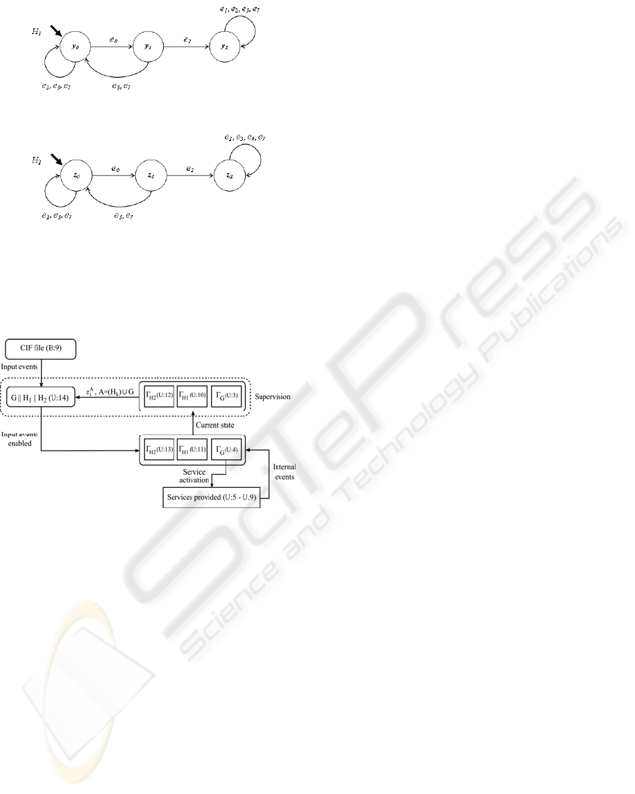
According to the H
1
state transition diagram
(Figure 3), the state y
1
represents the action
“performing home operation”. If it is completed
successfully (e
2
event), the state changes to y
2
. Given
that
)(
211
ye
H
Γ
∈
, then it is not possible to perform
any type of movement to any position.
Table 2: Defined events in G (C - controllable, NC - non
controllable).
Event Description Type
e
0
Request for performing a home
operation
C
e
1
Request for moving until the target
position is reached
C
e
2
Movement completed successfully NC
e
3
Request for stopping the current
movement
C
e
4
Request for changing the IMC 110
operation mode
C
e
5
Request for setting the velocity of
automatic movements
C
e
6
Request for setting the acceleration of
automatic movements
C
e
7
Emergency stop occurs NC
e
8
Emergency stop situation is finished NC
Taking into account the state transition diagram
(Figure 4) for H
2
, it is only possible to change to
automatic mode (e
4
event) if a home operation has
been completed successfully.
Diagrams H
1
and H
2
are structurally identical,
and both restrictions over G could have been
modelled by only one specification H. However,
modelling several modular specifications H
i
,
structurally simpler than H, is easier to verify and
understand (Cassandrass, 2007).
ICINCO 2009 - 6th International Conference on Informatics in Control, Automation and Robotics
266
In order to avoid these possible incidents, we use
the Supervised Control Theory. The framework we
propose allows modelling one or more specifications
which guarantee that the system behaves properly at
all times. This is achieved by temporarily disabling
the input events which could put the system at risk.
Our framework also differentiates between the
specifications and the functionality provided. Thus,
it is possible to modify both parts independently.
Figure 3: State transition diagram for H
1
.
To prove the main features of our framework,
some implementation issues must be solved, due to
the synchronous nature of PLC.
ACKNOWLEDGEMENTS
Figure 4: State transition diagram for H
2
.
In order to implement the supervisor system
(Figure 5), we have followed the proposed
framework, taking into account G, H
1
and H
2
defined previously.
The results presented at this paper have been
obtained from the tasks of research that have been
partially supported by the Spanish Ministery of
Science and Innovation through DPI2007-62267
proposal and by the Castilla y León Council with
SA030A07 project.
REFERENCES
Beck, J., Reagin, M., Sweeny, T., Anderson, R., Garner,
T. 2000. Applying a Component-Based Software
Architecture to Robotic Workcell Applications. In
IEEE Transactions in Robotics and Automation, vol.
16, pp. 207-217.
Curto, B., García, F. J., Moreno, V., González, J., Moreno,
A., 2001. Experience of a CORBA based architecture
for Computer Integrated Manufacturing. In ETFA’01,
8th IEEE International Conference on Emerging
Technologies and Factory Automation
, pp 765-769.
Figure 5: Implemented Supervisor System.
5 CONCLUSIONS
Ramadge, P. J., Wonham, W. M., 1987. Supervisory
Control of a Class of Discrete Event Processes. In
SIAM J. Control and Optimization, vol. 25, no. 1, pp.
206-230.
In this paper we propose a software framework
where the main aim is to make easier the
implementation of a supervisory control system over
a PLC. With this framework we want to emphasize
on the idea that the functionalities must be offered
with no effects on the robustness of the system
operation.
Chandra, V., Mohanty, S. R., Kumar, R., 2000. Automated
control synthesis for an assembly line using discrete
event system control theory. In IEEE Transactions on
Robotics and Automation.
Mušić, G., Matko, D., 2002. Discrete Event Control
Theory Applied to PLC Programming. In
AUTOMATIKA: Journal for Control, Measurement,
Electronics, Computing and Communications
, vol. 43
no. 1-2.
The system can be viewed as a well defined set
of services which are requested depending on the
production needs. Changes in the production process
can affect the order in which the services are
requested but not their implementation.
Phoha, V. V., Nadgar, A., Ray, A., Phoha, S., 2004.
Supervisory Control of Software Systems. In
IEEE
Transactions on Computer
, vol.53, nº9.
On the other hand, the flexibility obtained must
have nothing to do with the robustness demanded by
this kind of systems. Therefore we take into account
the possibility that certain event sequences could put
at risk the good working order of the system.
Cassandrass, C. G., Lafortune, S., 2007. Introduction to
Discrete Event Systems, Springer, 2
nd
edition.
APPLYING A SOFTWARE FRAMEWORK FOR SUPERVISORY CONTROL OF A PLC-BASED DISCRETE EVENT
SYSTEM
267
