
A SIMULATION SETUP FOR COMMUNICATION HARDWARE IN
THE LOOP EXPERIMENTS
Markus Sauer and Florian Zeiger
Zentrum f¨ur Telematik e.V., Allesgrundweg 12, Gerbrunn, Germany
Klaus Schilling
Department of Computer Science VII, University of W¨urzburg, Am Hubland, W¨urzburg, Germany
Keywords:
Networked mobile robots, Communication, Simulation.
Abstract:
Simulations are a very powerful tool in robotics to design and verify new algorithms before doing time-
consuming tests with real hardware. Nowadays, a lot of very realistic simulation environments are available to
simulate robot kinematics and dynamics and any type of multi-robot systems in a virtual physical environment.
Unfortunately, the communication in these simulations is often only considered in a very simplified matter,
although the characteristics of a real communication link are very complex and might have a strong influence
on the performance of a multi-robot algorithm. This contribution proposes a setup to perform communication
hardware in the loop tests with the 3D simulation environment USARSim. For this setup any communication
device which can be connected to a PC architecture like WLAN, UMTS or Bluetooth can be used. A coop-
erative collision avoidance algorithm is presented as an example which is realized with this setup, while real
hardware is used for the communication link between the robots. Finally, the limitations are presented.
1 INTRODUCTION
The progress in the area of telecommunication tech-
nology together with the demand of networked mo-
bile robot systems to assist humans in many different
areas (e.g. disaster management, security and surveil-
lance, or search and rescue applications) forces the
development of multi robot systems which incorpo-
rate several autonomy functions like formation driv-
ing and obstacle avoidance. Hereby, due to the re-
quired flexibility and dynamic communication topol-
ogy, distributed control algorithms are very desirable.
For the development of these mechanisms to control
and coordinate swarms of mobile systems or multi
robot systems capable simulation or emulation en-
vironments are a useful and necessary tool for effi-
cient development and analysis. But the use of simu-
lation environments for networked mobile robot sys-
tems also implies some consideration with respect to
significance and validity of the simulation. On the
one hand the complete dynamics and kinematics of
each system must be modeled appropriately. On the
other hand, also the available communication link in-
between the robots must be represented in a suitable
manner. With respect to the simulation of the dynam-
ics and kinematics of mobile robots in multi robot sys-
tems several simulation environment were developed
in the recent years. Two well-known examples of the
many available simulators are Player/Stage (Gerkey
et al., 2003) and USARSim (Carpin et al., 2007).
Player is a robot device server to realize multi-robot
or sensor-network systems. Stage can be used to-
gether with Player and can simulate large populations
of robots in a 2D environment. USARSim is based on
the famous Unreal Tournament 2004 game engine. It
is a general purpose 3D - multi-robot simulator which
provides basic physical properties of the robot and
the simulated environment which closely match the
real implementation of the robots and the real envi-
ronment. In addition, it is also possible to simulate
camera images from cameras inside the simulation.
Compared to Player/Stage it is only a simulation with-
out a device server and controller concept like Player.
Figure 1 shows a typical environment simulated with
USARSim for the virtual RoboCup Rescue league.
With respect to the simulation of the communica-
tion link also many approaches and even products are
available to be integrated. Of course, the importance
of these simulations of communication link technolo-
gies is not only limited to the area of multi robot sys-
312
Sauer M., Zeiger F. and Schilling K. (2009).
A SIMULATION SETUP FOR COMMUNICATION HARDWARE IN THE LOOP EXPERIMENTS.
In Proceedings of the 6th International Conference on Informatics in Control, Automation and Robotics - Robotics and Automation, pages 312-317
DOI: 10.5220/0002218703120317
Copyright
c
SciTePress
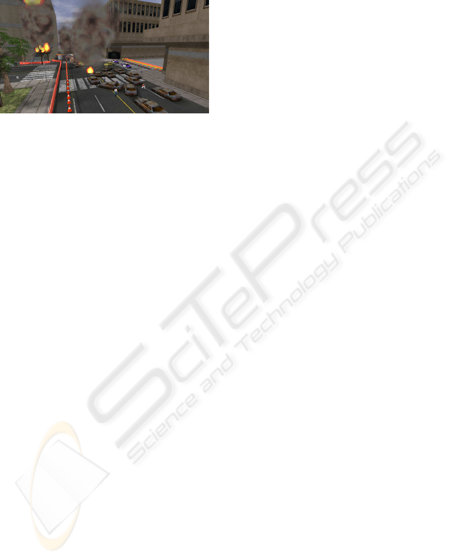
Figure 1: Typical environment simulated for the virtual
RoboCup Rescue with USARSim.
tems. In the area of network testing and evaluation of
wireless network systems (Doshi et al., 2007) often
the QualNet network simulator is used for the setup
of real-time emulations. This simulator is also used
in (Xu et al., 2003) for simulations regarding quality
of service provisioning in wireless ad-hoc networks,
as well as in (Bagrodia et al., 2006), where a sys-
tems simulation environment for future combat sys-
tems is presented. In the area of networked haptic
virtual environments (Sankaranarayanan et al., 2007)
used NIST-Net to create realistic Internet-like charac-
teristics in a laboratory setting. NIST-Net (cf. (Car-
son and Santay, 2003)) is a tool to facilitate testing
and experimentation with network code through emu-
lation which can model communication performance
characteristics like packet delay, jitter, bandwidth lim-
itations, congestion, and packet loss.
Of course, there exist other powerful simulation
tools like NS2 or OPNET. All these simulation en-
vironments are very mighty tools which have focused
on the simulation of the characteristics of the commu-
nication channel. Unfortunately, they are often very
complex and time-consuming to operate and most of
them cannot be easily integrated with the simulation
environments for mobile robot dynamics and kine-
matics mentioned before. It is also known that the
simulation tool itself influences the outcome of a sim-
ulation (Liu and Kaiser, 2005). In addition, you need
to test the algorithm anyway later with real commu-
nication hardware. Currently, in the area of simula-
tion of networked robot systems and robot swarms
the simulation of the communication interface is of-
ten represented in a very abstract or simplified way.
Nevertheless, several publications for networked con-
trol systems turned out the importance of the knowl-
edge about the communication characteristics and its
influence on the implemented control algorithms. In
(Lopez et al., 2006), experiments of closed-loop net-
worked control systems are evaluated focusing specif-
ically on the performance and time delays effects
for different compensation actions. In (Wei et al.,
2001) stability of networked control systems is in-
vestigated for differentnetwork-schedulingprotocols.
Also methods for compensating network-induced de-
lay are presented together with experimental results
for networked control systems with packet loss on the
communication link. (Walsh et al., 2002) provided an
analytical proof of global exponential stability for a
novel control network protocol and commonly used
statically scheduled access methods. There, the fo-
cus is set on communication constraints which are
imposed by the network and the performance of the
proposed protocol and the statically scheduled pro-
tocols are examined in simulations. As above men-
tioned, the behavior of the communication channel is
very important for the analysis and implementation
of coordination and distributed control algorithms for
networked robotic systems and may influence the be-
havior of the complete system. Thus, this work pro-
poses an approach how real communication hardware
can easily be included into hardware simulation en-
vironments - in this case USARSim. The communi-
cation hardware is used as in real world applications
but nevertheless directly integrated to the algorithms
to be analyzed. The environment consisting in a map
and the dynamics and the kinematics of the physical
entities (mobile robot clients) is provided by the US-
ARSim server. This modular design allows flexible
extensions in terms of replacing the simulated robot
hardware by real mobile robot hardware which accel-
erates the development duration of multi robot sys-
tems. As the proposed system integrates real wire-
less communication hardware and standard protocol
stacks directly into the simulation an intensive anal-
ysis of implemented coordination and control algo-
rithms for robot teams under consideration of the ef-
fects of real wireless communication is possible.
The remainder of this work is structured as fol-
lows. First, the hardware in the loop setup which
integrates the real communication stack in the sim-
ulation is introduced. Then an implementation of a
cooperative collision avoidance algorithm as example
application is presented. Afterwards, the areas and
the constraints of the proposed setup are investigated.
2 HARDWARE IN-THE-LOOP
SETUP
The objective of the simulation system design is the
use of real communication hardware while simulating
multiple robots with USARSim. Therefore, the pre-
sented system can be divided into three main parts: a
local area network segment, the clients, and a wireless
communication segment (cf. Figure 2).
A SIMULATION SETUP FOR COMMUNICATION HARDWARE IN THE LOOP EXPERIMENTS
313
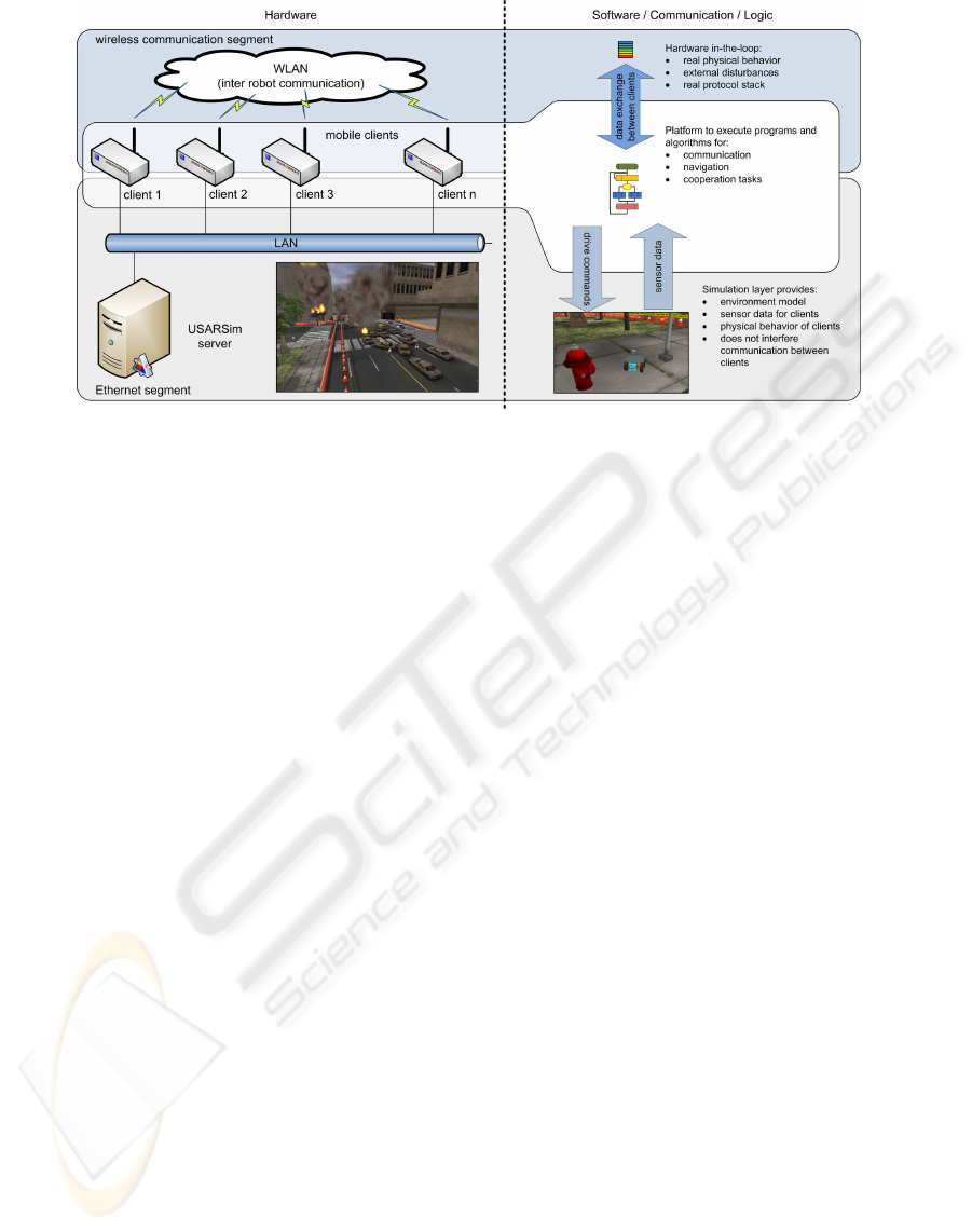
Figure 2: Setup of Hardware in-the-loop Simulation Components.
2.1 Hardware Setup
The local area network segment uses standard Ether-
net communication to provide connectivity between
the USARSim server and all clients which supports
high bandwidth communication with low delays. This
connection is used for the exchange of drive com-
mands and sensor data between the USARSim simu-
lation environment and the different clients. This seg-
ment represents the indirect communication between
each client and its environment, and as it is realized
via the Ethernet segment, the direct communication
between each client over the wireless link is not inter-
fered. Communication between the clients is not im-
plemented via this link. The clients are equipped with
a mini PC architecture with 1200MHz, 1GB RAM,
a 8GB compact flash card as hard disk, and Debian
Etch as operating system provides a platform to exe-
cute the programs and algorithms for navigation and
cooperation tasks which should be investigated and
analyzed. This mini PC represents the computing
power of a single robot. The LAN segment is only
used by each client to retrieve environment data from
the USARSim server. Communication between the
clients is only realized via the wireless communica-
tion segment. The wireless segment is based on IEEE
802.11 wireless LAN and represents the communi-
cation hardware which is directly integrated into the
simulation setup. This communication link is exclu-
sively used for the communication between all clients
i.e. robots and human operators. As a standard oper-
ating system is used the correspondingprotocol stacks
are available and also routing mechanisms for wire-
less ad-hoc networks like OLSR, DSR, or AODV can
easily be used.
2.2 Software Components
For each of the hardware components described in
Section 2 also dedicated software components are
existing. On the simulation layer a USARSim server
is running which provides an environment model,
the physical behavior of the clients, and sensor
data for clients. As only the Ethernet segment is
used for the communication between the USARSim
server and the clients, the inter client communication
via the wireless segment is not affected. On the
clients no specific installation for the USARSim
simulation and for maintaining the connection to the
USARSim server is required. The communication to
the USARSim server, and respectively the simulated
robots are realized with simple string messages over
TCP-socket (Carpin et al., 2007). Each client is
running on one of the described mini PC. Basically
here, the distributed control algorithms can be
implemented. Furthermore, the operating system
is also maintaining the communication link to the
USARSim server for sensor data acquisition and
sending commands. The client PCs are also equipped
with WLAN PCMCIA cards supporting the IEEE
802.11 b/g standard. The wireless communication
is exclusively used for inter-client-communication
which represents one of the key issues of the pro-
posed architecture. In the presented setup all standard
protocol versions which are available for the client
operating system (e.g. Debian Linux) can be used.
As the wireless communication link is exclusively
used for inter client communication, the real protocol
stacks and real physical behavior of the link allows
for meaningful hardware in-the-loop simulations.
Thus, the navigation, coordination and cooperation
ICINCO 2009 - 6th International Conference on Informatics in Control, Automation and Robotics
314
algorithms which should be analyzed are exchanging
data via communication links with a realistic behav-
ior - including external disturbances.
2.3 The Simulation System Design
This system setup is designed as simulation envi-
ronment for network control systems and scenarios
of robots or robot formation driving with real IEEE
802.11 wireless LAN communication. In this work,
one client represents the formation leading robot and
the other three clients are robots which should keep
a certain formation. The leading robot sends its po-
sition data with a frequency of 10Hz to the other
team members via the wireless link. A communica-
tion from the team members back to the leader is not
present. The communication between the USARSim
server and each client uses the standard USARSim in-
terface based on TCP connections. All robots run the
same distributed cooperative collision avoidance al-
gorithm while moving to their respective goal points.
3 EXAMPLE: COOPERATIVE
COLLISION AVOIDANCE
Typically, distributed control algorithms for robotic
networks (Bullo et al., 2008) often assume a cer-
tain simplified model of the communication channel.
Here, a setup is proposed to test these control algo-
rithms with a real communication stack. As applica-
tion example for this contribution, a cooperative col-
lision avoidance control algorithms based on the con-
cepts of (Stipanovi´c et al., 2007) is used.
In the example scenario, a group of n mobile
robots should move through an environment without
colliding with objects in the environment or with each
other. There is no central instance coordinating the
movement of the robots. In the shown simulation mo-
bile robots with differential drive are used. They are
equipped with a simulated laser range finder for ob-
stacle detection. The laser range finder has a field
of view of 180 degree and is mounted to the front
of the robots. The leader robot a
i=1
drives a rhom-
bus in this environment and continuously sends its
pose to the other following n− 1 robots. The robots
a
i∈{2..n}
receive this pose over the wireless communi-
cation segment and set their own new goal pose rela-
tive to the pose of the received leader pose. Thus, the
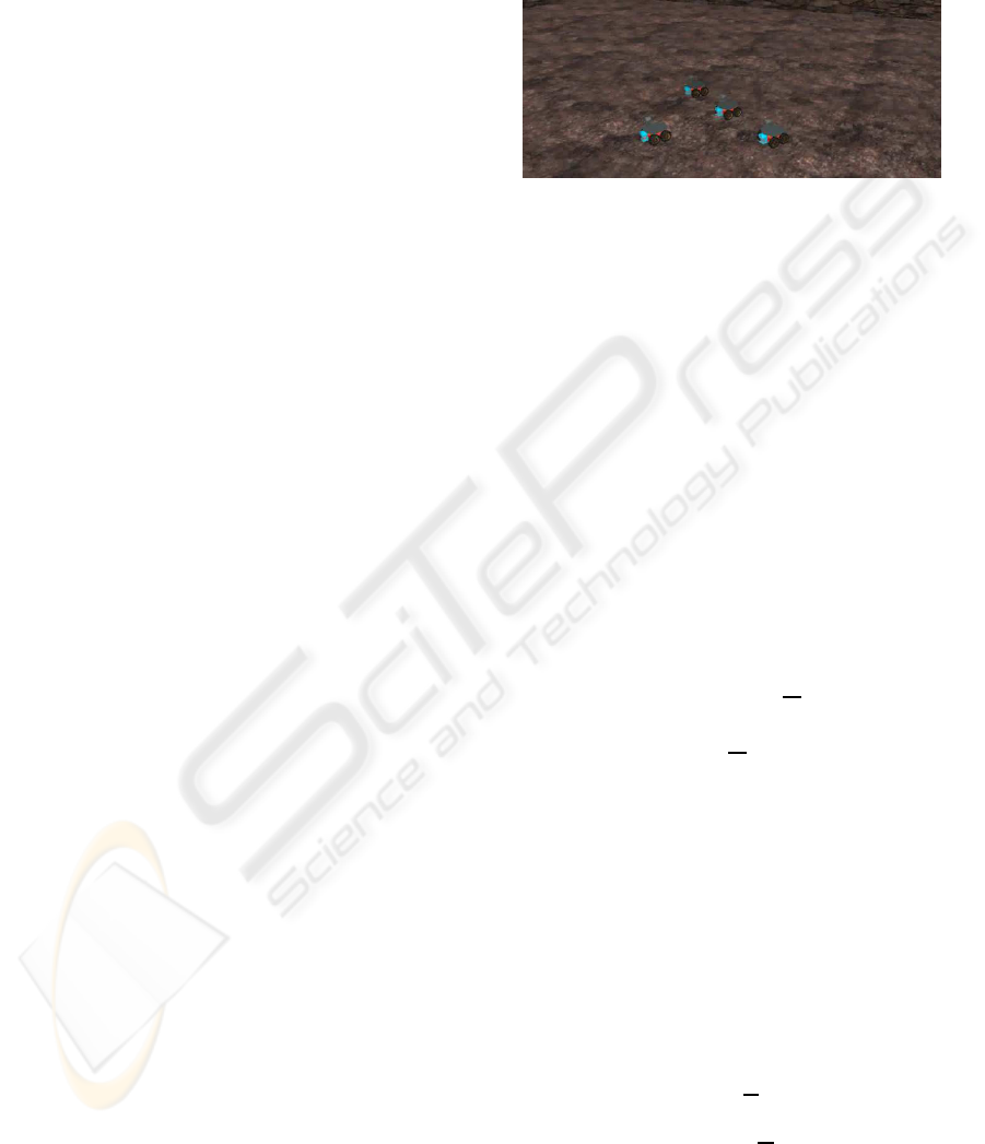
formation shown in Fig.3 is established in equilibrium
of the controller. Any other logical communication
topology can be realized with this kind of setup e.g.
robot one can only communicate with robot two and
robot three and four can only communicate with robot
two. This is especially interesting for the investigation
of the system behavior of distributed algorithms with
communication constraints.
Figure 3: Relative positioning of the robots in formation.
For the presented example application, the mobile
robots are modeled with the kinematics of a differen-
tial drive robot as first order system (cf. equation 1);
˙x
i
= v
i
· cosΘ
i
˙y
i
= v
i
· sinΘ
i
˙
Θ
i
= ω
i
(1)
x
i
, y
i
, and Θ
i
denote the pose of the robot i. v
i
is
the translational velocity and ω
i
the turn rate. On each
of the robots a combination of the following position
controller and a controller for obstacle avoidance is
implemented. The controller switches between dif-
ferent behaviors depending on the current conditions.
Without obstacles in the defined obstacle avoidance
zone and the robot’s orientation is not towards the
goal (Θ
i
6= Θ
gi
) the following controller applies:
˙
Θ
i
= −(Θ
i
− Θ
gi
) =
r
i
L
i
(u
ri
− u
li
)
⇒(u
ri
− u
li
) = −
L
i
r
i
(Θ
i
− Θ
gi
) (2)
r
i
denotes the radius of the i-th robots’ wheels, L is the
length between the wheels, u
ri
is the left wheel speed,
u
ri
is the right wheel speed respectively and Θ
gi
is the
desired orientation towards the currently defined goal.
If the robot is oriented towards the goal (Θ
i
−
Θ
gi
) < t
o
(t
o
- threshold for accuracy of orientation
of robot towards goal), v
i
is aligned with the straight
line between the robot’s position and the goal posi-
tion. Therefore, v
i
only applies to ˙x
i
in the robot co-
ordinate frame ˙x
i
= v and ˙y
i
= 0. The following con-
troller can be applied:
v
i
= −x
i
=
r
i
2
(u
li
+ u
ri
)
⇒u
ri
= u
li
= −
x
i
r
i
Θ (3)
In the robot coordinate frame x
i
is under the above
given conditions equal to the distance between robot
and current goal and it becomes zero if the desired
A SIMULATION SETUP FOR COMMUNICATION HARDWARE IN THE LOOP EXPERIMENTS
315
goal is reached. If an obstacle is in the defined sens-
ing range, the controller is adapted according to the
following rules: First a vector F
oi
is calculated. F
oi
points in opposite direction of the nearest obstacle to
the robot and its length increases indirect proportional
with the distance to the next obstacle. Then this vector
is combined with the normalized vector in goal direc-
tion F
gi
to a new goal direction vector incorporating
an obstacle avoidance component and a new desired
heading Θ
oai
(cf. Figure 4):
F
oai
= (F
oi
+ F
gi
) (4)
Θ
oai
= arctan2(y
oai
, x
oai
) (5)
Finally, this value is inserted in the controller defined
in Equation 2:
˙
Θ
i
= −(Θ
i
− Θ
oai
) =
r
i
L
i
(u
ri
− u
li
)
⇒(u
ri
− u
li
) = −
L
i
r
i
(Θ
i
− Θ
oai
) (6)
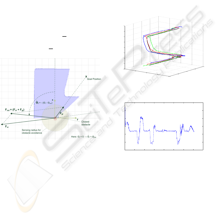
Figure 4: Overview of the different values for the obstacle
avoidance controller.
After orientation towards Θ
oai
the robot always
movesfor a small time period in this direction to avoid
oscillations in reorienting due to the limitation of the
obstacle sensing to 180 degrees. This translational
movement is only done in cases where definitely no
collision can occur.
The experiments with this cooperative collision
avoidance algorithm were done with n = 4 robots.
The results can be seen in Fig. 5 and Fig. 6. Fig.
5 shows how the four robots move with respect to
each other over time while the three robots follow the
leader robot driving a predefined rhombus trajectory
for a certain experiment time. In each plane at a cer-
tain time the position of the robots at this times can be
seen. The 3D plot of the trajectories shows the reori-
entation of the formation at the edges of the rhombus
over time and it can be seen that there was now col-
lision because none of the trajectories is touching or
crossing each other. Fig. 6 shows the minimum dis-
tance inside the group of mobile robots. The relative
position of the three following robots was designed to
have a distance minimum of 1.7m between all robots
when they are moving in perfect formation. In ad-
dition the robots should never get closer then 0.4m.
Fig. 6 shows that the algorithm satisfies these require-
ments. The peaks in the graph occur always when the
formation is reorienting at the edges of the rhombus
driven by the leader robot.
−10
−5
0
5
10
−20
−10
0
10
20
0
0.5
1
1.5
2
2.5
3
3.5
4
x 10
5
x−position [m]
y−position [m]
time [ms]
Figure 5: Position of each robot while driving in formation.
0 0.5 1 1.5 2 2.5 3 3.5 4
x 10
5
0.5
1
1.5
2
2.5
3
3.5
time [ms]
minimum distance [m]
Figure 6: Minimum distance occurring between all robots
inside the formation.
4 APPLICATION AREAS AND
CONSTRAINTS
This simulation setup is designed for real communi-
cation hardware in-the-loop simulations of networked
robotics scenarios. The advantage of this special
setup is, that the real communication protocol stack
is used which saves the very complex simulation of
the protocol stack and the physical behavior of the
link. A well suited application area of this system is
in the simulation of swarms, multi-robot teams, and
ICINCO 2009 - 6th International Conference on Informatics in Control, Automation and Robotics
316

formation driving. In these scenarios, control algo-
rithms can be tested and evaluated under the influence
of real communication link behavior (limitations in
medium access etc.) and also different communica-
tion protocols can be tested easily. Of course, also
some limitations exist. As the hardware nodes are lo-
cated quite close to each other, long distance com-
munications and the consequential channel behavior
cannot be simulated. Nevertheless, for detailed sim-
ulations of the interaction of communication proto-
cols, control engineering and the underlying system
in multi-robot teams and formation scenarios, the pre-
sented architecture is suites very well and allows an
easy and fast setup of significant simulations.
5 CONCLUSIONS
In order to simulate the behavior of networked multi-
robot systems in general a model for the communica-
tion channel has to be to implemented and verified.
In most cases this is only possible with simplifica-
tions and limitations and the simulated channel is not
representing a real communication channel anymore.
Therefore, the conclusions drawn from the simulation
of the tested algorithm might not be as meaningful as
desired.
The presented approach offers a possibility to re-
alize easily a meaningful simulation with real com-
munication hardware for network robotic scenarios.
It provides the exact behavior of the complete, com-
plex communication stack without any approximation
or simplifications. Thus, the behavior of multi-robot
algorithms can be directly investigated with all the
changes in the communication and data flow between
the robots. In the combination with a simulator like
USARSim is is possible to simulate network robotic
systems with basic physics and real communication.
The setup of a hardware communication in the
loop simulation is much easier than the setup of a
meaningful communication channel simulation com-
bined with a multi-robot simulation. There are even
less uncertainties in the behavior of the system when
you later go to real hardware.
Therefore, it is very easy to test the behavior of
algorithms for typical applications of network control
systems like teleoperation of robots or robot forma-
tion driving with a real communication channel be-
fore going to the real hardware. Due to the standard-
ized interfaces which are used, such kind of setups
also allow for an easy evaluation of different type of
wireless communication systems like e.g. WLAN,
UMTS, HSDPA/HSUPA, Bluetooth, WiMax. Espe-
cially testing of swarm behavior is very meaningful,
because like in the real system naturally the nodes in
the communication hardware in the loop simulation
are very close to each other.
REFERENCES
Bagrodia, R., Tang, K., Goldman, S., and Kumar, D. (2006).
An accurate, scalable communication effects server
for the fcs system of systems simulation environment.
In Proceedings of the Winter Simulation Conference.
Bullo, F., Cort´es, J., and Mart´ınez, S. (2008). Dis-
tributed Control of Robotic Networks. Princeton Se-
ries in Applied Mathematics. Princeton University
Press, Princeton, NJ.
Carpin, S., Lewis, M., Wang, J., Balakirsky, S., and Scrap-
per, C. (2007). Usarsim: a robot simulator for research
and education. In 2007 IEEE International Confer-
ence on Robotics and Automation (ICRA’07).
Carson, M. and Santay, D. (2003). Nist net: a linux-based
network emulation tool. SIGCOMM Computer Com-
munication Review archive, 33(3):111 – 126.
Doshi, S. R., Lee, U., and Bagrodia, R. L. (2007). Wireless
network testing and evaluation using real-time emula-
tion. ITEA Journal of Test and Evaluation, 28(2).
Gerkey, B., Vaughan, R. T., and Howard, A. (2003). The
player/stage project: Tools for multi-robot and dis-
tributed sensor systems. In 11th International Confer-
ence on Advanced Robotics (ICAR), pages 317–323,
Coimbra, Portugal.
Liu, C. and Kaiser, J. (2005). A survey of mobile ad hoc
network routing protocols. Technical report, Univer-
sity of Magdeburg, TR-4: Middleware for Network
Eccentric and Mobile Applications (MINEMA).
Lopez, I., Piovesan, J., Lee, C. A. D., Martinez, O., Spong,
M., and Sandoval, R. (2006). Practical issues in net-
worked control systems. In Proceedings of the Amer-
ican Control Conference.
Sankaranarayanan, G., Potter, L., and Hannaford, B. (2007).
Measurement and emulation of time varying packet
delay with applications to networked haptic virtual en-
vironments. In RoboComm - First International Con-
ference on Robot Communication and Coordination.
Stipanovi´c, D. M., Hokayem, P. F., Spong, M. W., and
ˇ
Siljak, D. D. (2007). Cooperative avoidance control
for multiagent systems. Journal of Dynamic Systems,
Measurement, and Control, 129(5):699–707.
Walsh, G., Hong, Y., and Bushnell, L. (2002). Stability
analysis of networked control systems. IEEE Transac-
tions on Control Systems Technology, 10(3):438–446.
Wei, Z., Branicky, M., and Phillips, S. (2001). Stability of
networked control systems. Control Systems Maga-
zine, IEEE, 21(1):84 99.
Xu, K., Tang, K., Bagrodia, R., Gerla, M., and Bereschin-
sky, M. (2003). Adaptive bandwidth management and
qos provisioning in large scale ad hoc networks. In
Proceedings of MILCOM’03.
A SIMULATION SETUP FOR COMMUNICATION HARDWARE IN THE LOOP EXPERIMENTS
317
