
IMPLEMENTATION OF A FUZZY LOGIC SYSTEM ON A FPGA
FOR A SERVO CONTROLLER
Arturo Téllez V., Luis A. Villa V., Herón Molina L. and Oscar Camacho N.
Centro de Investigación en Computación, Instituto Politécnico Nacional
Juan de Dios Batiz Ave. s/n, Nueva Industrial Vallejo, Mexico City, Mexico
Keywords: DC Servo Control, Fuzzy Logic Controller, Fuzzy Sets Adaptation, Combinatorial Design, FPGA,
Hardware.
Abstract: In this paper we propose a digital fuzzy logic system implemented on a field programmable gate array
(FPGA) in order to control a servo controller. The fuzzy logic controller (FLC) is designed as a
combinational circuit and does not depend on a clock signal. So the advantage is that the fuzzy system is
enough fast to control a servo controller. For the implementation of the membership functions (MF) we
propose to use dynamic MF, i.e. the parameters that define the each MF are adapted on line. Also, for the
design of fuzzy system a new methodology was developed so the design and implementation of the fuzzy
system is easy to do. The fuzzy system was programmed in MATLAB and was proved that the fuzzy system
is capable to control a servo motor. Finally the performance of the fuzzy system was proved directly on the
FPGA.
1 INTRODUCTION
There had been many implementations of hardware
FLC since the first one (Togai, 1986). Each one with
some differences related to the processing way.
A FLC can be implemented in three forms:
Runtime Computing (RTC), Lookup Computing
(LUC) or mixed. It can also be combined with
several computer architecture techniques like
combinatorial, sequential, pipelined and mixed
processing, implemented in a computer, a
microcontroller or any programmable device.
The use of FPGA in a reconfigurable device has
been suitable when talking about versatility to make
any digital design by means of costs and design
time. It is a dare to play with these architectures and
techniques to make an appropriated FLC design, by
which it is necessary to change the way of designing
algorithms to describe an improved FLC.
This paper shows a practical approach for the
design of a combinatorial FLC for a DC servo using
simple construction modules on a FPGA in order to
speed up the FLC prototyping.
2 FUZZY LOGIC CONTROLER
This FLC uses a Mamdani fuzzy model. The Fuzzy
system is described by the next equation:
(1)
Where is the system output,
, and
,
,...,
;
= center of the
output of each membership function. Each input is
assigned to a set of membership functions, for
instance,
represents all possible membership
functions for the first input variable. The FLC only
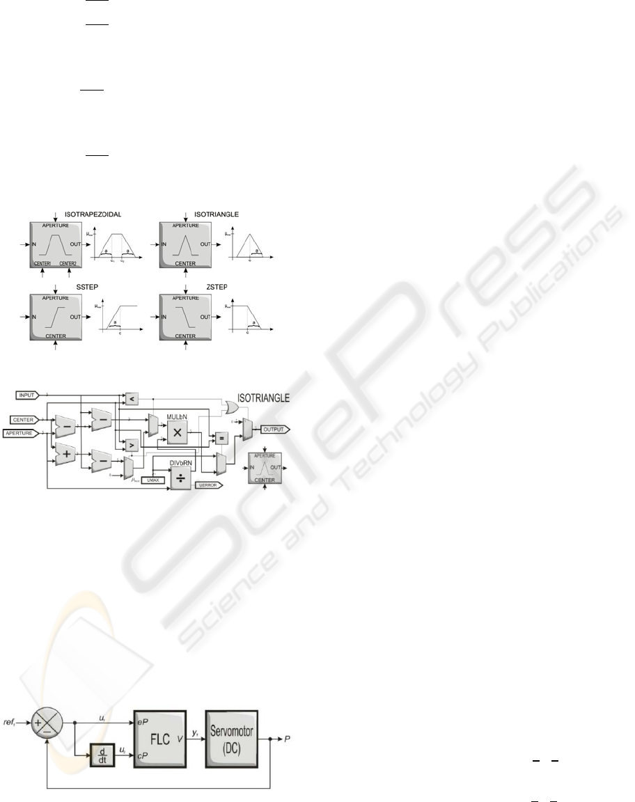
uses triangles, S and Z membership functions for
fuzzy sets.
This FLC has only two inputs and one output,
each input is described by three membership
functions which were implemented in hardware
according to equations 2- 4, which are shown in
Figure 1.
The Triangle function is described by:
89
Téllez V. A., Villa V. L., Molina L. H. and Camacho N. O. (2009).
IMPLEMENTATION OF A FUZZY LOGIC SYSTEM ON A FPGA FOR A SERVO CONTROLLER.
In Proceedings of the International Joint Conference on Computational Intelligence, pages 89-93
DOI: 10.5220/0002323700890093
Copyright
c
SciTePress
,
,
,
0,
(2)
The S function is described by:
,
,
0,
(3)
And the Z function is described by:
,
,
0,
(4)
Figure 1: Several hardware suitable membership functions.
Figure 2: Design of an isosceles triangle as membership
function.
All the register transfer level (RTL) description,
which shows the design of data flow, was made with
VHDL. As shown in Figure 2, triangular function
uses division and multiplication algorithms. Also, S
and Z functions describe a similar performance.
Next section shows the design methodology that
was purposed for building combinatorial FLC, and
the architecture of each module of the fuzzy system
controller for the servo.
Figure 3: Fuzzy Logic Control System for a DC servo
motor.
3 DESIGN
FPGA technology facilities and advantages let the
designer to build any fuzzy system in short time. We
purpose a fast and simple approach for FLC design
which consists with eight steps in order to
implement it on FPGA:
1. Establish whatever the designer want to control
and which variables will be related. Define the
number of inputs and outputs of the FLC.
2. Define the universe of discourse for each input
and output variable based on the process
characteristics.
3. Define the number and shapes of fuzzy sets for
every variable based on the last step.
4. Establish the FLC configuration by means of
the fuzzy inference rules according to the
wished operation and based on the expert
knowledge about the process.
5. Build the fuzzifier using simple membership
functions connected in parallel.
6. Build the inference machine based on step 4,
by means of MIN- MAX modules.
7. Build the defuzzification stage by means of
multiplication and division modules using
parallelism.
8. Implement the design on FPGA.
Considering the FPGA limitations, it is possible to
build any fuzzy system.
STEP 1. Assume a fuzzy control system for a
DC servomotor which consists of two inputs and
one output, as shown in Section 2. First input
variable
is the rotor “position error” which is
the difference between current position and
desired position. Second input variable
is the
change of that position error (“change in
position”) in order to know if the error is
increasing or decreasing. The output variable
is the needed applied voltage to move the rotor
servo to a certain position (Figure 3).
STEP 2. Before choosing the number of
membership functions or fuzzy sets for this
system, it is needed to establish the size of the
discourse universe for every variable. Expert
should purpose those values. So, position error
must be expressed in radians () and it must
not be greater than half turn –
,
. And
change in position should accept non- abrupt
changes in error position –
,
; this
variable rises from position error derivative. For
every input it is required to get the minimum
possible error as possible or zero. This ranges let
IJCCI 2009 - International Joint Conference on Computational Intelligence
90
the FLC to control the servo rotor position by
means of varying the voltage supply from -5 to 5
volts.
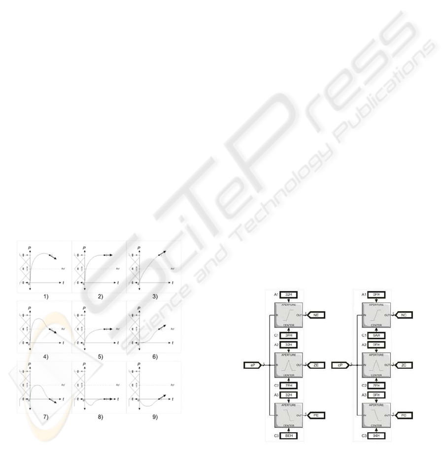
STEP 3. Once the universe of discourse is
defined, the designer may purpose the number
and the shape (membership function) of the
fuzzy sets and establish their linguistic meaning.
By simplicity, for every variable, we purpose
three fuzzy sets that describe the triangular, S
and Z membership functions, and their linguistic
labels for every variable. For position error: NE
(negative error), ZE (zero error) and PE (positive
error); for change in error variable: NC (negative
change), ZC (zero change) and PC (positive
change); and for voltage variable: NV (negative
voltage), ZV (zero voltage) and PV (positive
voltage). The fuzzy sets distribution is a task for
the designer also.
STEP 4. The FLC configuration is made by
their rule set. The number of rules (Equation 5)
is defined by the number of fuzzy sets per input
variable (
number of fuzzy sets for input
position error,
number of fuzzy sets for input
change in position):
3
3
9
(5)
These nine rules are nine possible cases that may
occur in the FLC inputs, shown in Figure 4.
Figure 4: Graphical representation of nine rule cases for
the servo application.
In order to get the right FLC configuration it is
needed to analyze the process entirely for covering
all the possible cases in which it exist a non- desired
operation. So, FLC can assure there is a concrete and
exact value in its output that contributes for a right
control action.
Then, the rule set can be built this way:
1.
IF
e
P
isNEAND
c
P
isNC THEN
V
isNV
2.
IF
e
P
isNEAND
c
P
isZC THEN
V
isNV
3.
IF
e
P
isNEAND
c
P
isPC THEN
V
isNV
4.
IF
e
P
isZEAND
c
P
isNC THEN
V
isNV
5.
IF
e
P
isZEAND
c
P
isZC THEN
V
isZV
6.
IF
e
P
isZEAND
c
P
isPC THEN
V
isPV
7.
IF
e
P
isPEAND
c
P
isNC THEN
V
isPV
8.
IF
e
P
isPEAND
c
P
isZC THEN
V
isPV
9.
IF
e
P
isPEAND
c
P
isPC THEN
V
isPV
STEP 5. Due to the use of RTC approach, it is
possible to build a combinatorial FLC that may
change its fuzzy set parameters on line,
regardless on their shape. Symmetric trapezoidal,
triangular, S and Z membership functions are
practical and suitable fuzzy sets for
implementing on FPGA.
STEP 6. All these membership functions,
shown in Figure 1, use the arithmetic operation
of division and multiplication for calculating
their corresponding slopes. In step 3, it was
chosen triangular, S and Z functions for the
fuzzy sets of every variable of the FLC fuzzifier,
so it is needed to establish their parameters
according to their corresponding range. This
range must be scaled according to the FLC bits
number. This way, fuzzifiers in Figure 5 show
parallel operation. Notice every fuzzy set
parameter can be changed simply by modifying
their register values.
Figure 5: Fuzzifiers for servo application. Every input
variable has three fuzzy membership values.
IMPLEMENTATION OF A FUZZY LOGIC SYSTEM ON A FPGA FOR A SERVO CONTROLLER
91
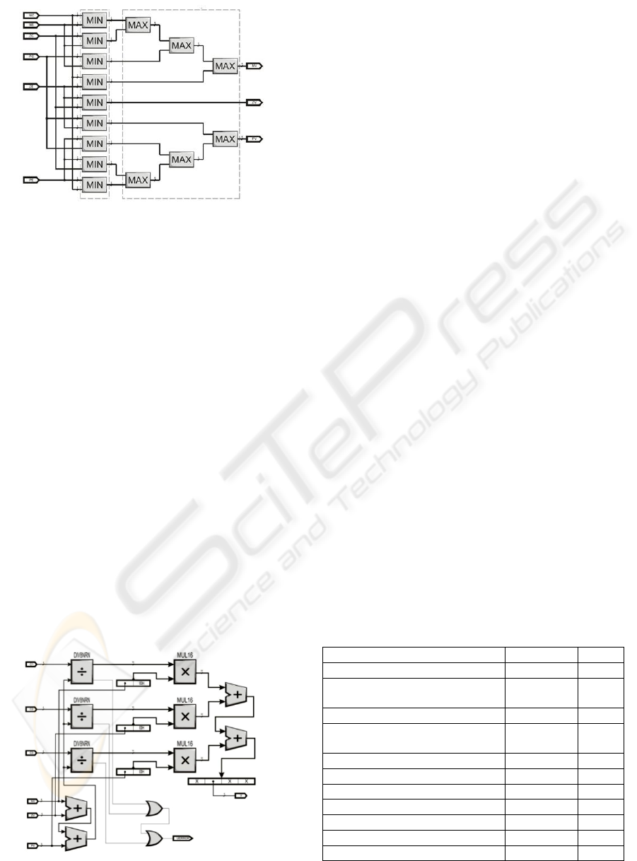
Figure 6: Inference Machine for servo application. All
implied premises drive to a consequence.
STEP 7. Inference Machine is made using
Mamdani Implication Method, where all every
output relates all the implied premises using
simple MIN/ MAX operations according to the
rule set, established in step 4. Figure 6 shows this
rule set by means of combinatorial circuit
connections.
STEP 8. Defuzzification is needed for
converting all fuzzy values onto crisp values in
order to use them for a specific control action.
RTC combinatorial fuzzification stage let the
expert change the singleton positions over the
output discourse universe on line. This
defuzzifier uses centroid technique, where every
singleton position is divided (modified non-
restoring division) by the summation of the
membership values obtained from the inference
machine and this result is multiplied by every
fuzzy value obtained from the inference
machine. Finally every multiplication result is
summed in order to obtain the crisp output.
Figure 7 shows this RTL design for this servo
application.
Figure 7: Defuzzification stage for servo application.
Centroid calculation.
STEP 9. Finally, once this design is
synthesized for a FPGA it is ready to upload.
Designer should take in account the pins number
in order to fit the specific application. Due this
application has only two inputs and one output
there is not any problem to fit the most of recent
FPGAs.
4 RESULTS
A general result for FPGA implementation was
obtained and this is resumed in Table 1 for Xilinx
Spartan FPGA starter kit. This results mean show
the delay time each module takes and the entire FLC
performance. Also, it is shown the total used LUTs
in FPGA resources.
Division algorithm is the slowest module in the
FLC. So, the more the division algorithm
performance improvement is made the more the
FLC performance will increase.
This fuzzy system was built in MATLAB Fuzzy
Toolbox first (FIS). Then it was chosen a set of
representative values called test bench and it is
applied to the FIS in order to prove the FLC
performance once it is implemented in FPGA kit.
DC servo FLC needs 84 ns to make an inference.
Then, its processing data rate is 11.9 MFLIPS. Table
2 shows a set of FLC implemented on FPGA with
RTC, LUT and mixed approaches, with similar FLC
configuration, but for different applications. Each
implemented FLC has similar and higher
performance compared with the purposed in this
paper, but the advantage of this method is the easy
scaling for system improvement or other application
designs.
Table 1: FPGA timing and resource results obtained for
DC servo control.
Algorithm Delay (ns) LUT
16 bits non-restoring division 48.50 644
Modified 8 bits non-restoring
division
28.83 208
8 bits multiplication 13.17 36
Isosceles triangle MF
36.70
14.51
251
S-step MF 36.70 249
Z-step MF 36.70 251
Fuzzifier 37.42 755
Defuzzifier 41.49 677
Mamdani inference machine 19.32 242
MIN-MAX operations 9.36 16
FLC 84.01 2689
IJCCI 2009 - International Joint Conference on Computational Intelligence
92

Table 2: Other hardware FLC with similar fuzzy systems.
Velocity performance comparison.
MFLIPS Device Autor
50.00 Undefined (Manzoul, 1995)
50.00 Undefined (Lund, 2000)
15.38 Xilinx XC3S1500 (Deliparaschos, 2005)
11.90 Xilinx XC3S200 (Tellez, 2008)
10.00 Xilinx XC3042,64 (Kim, 1997)
9.00 Xilinx XC4008 (Hung, 1994)
8.00 Altera EPF8820 (Aranguren, 1997)
5.56 Xilinx XC3S200 (González, 2007)
3.13 Xilinx XC3S1000 (Sánchez, 2007)
2.00 Xilinx XCV600E (Gaona, 2003)
0.08 VLSI (Togai, 1986)
5 CONCLUSIONS
A fuzzy logic controller was designed and
implemented on FPGA. Specifically the FLC was
implemented on a Xilinx design board. The
architecture of the system was implemented by
arithmetic modules by using combinational logic. In
order to implement the fast FLC prototyping we
proposed a methodology design of 8 basic steps. The
digital design was development with VHDL. Each
module was proved with ModelSim XE III Starter
version. The FLC has the characteristic that the
parameters of the membership functions are variable
on line. The complete fuzzy system for a servo
motor was probed with MATLAB and ModelSim.
ACKNOWLEDGEMENTS
Research supported by the Instituto de Ciencia y
Tecnología ICyTDF funding (Award No. PICCT08-
22) and by matching funding by IPN (Award No.
SIP/DF/2007/143).
REFERENCES
Téllez, A., 2008. Fuzzy Logic Controller Architecture
using Combinatorial Logic, Instituto Politécnico
Nacional. Centro de Investigación en Computación.
Mexico City.
Patyra, M. J.; Mlynek, D.M.; “Fuzzy logic:
implementation and applications;” Wiley; 1996.
Oberman, S. F.; Flynn, M. J.; “Division Algorithms and
Implementations;” IEEE Transactions on Computers;
Aug 1997; Vol 46, No. 8; pp. 833–854.
Togai M.; Watanabe H.; “Expert system on a chip: An
engine for real–time approximate reasoning;” IEEE
Expert Syst. Mag., 1986, pp. 55–62, Volume 1.
Manzoul, M.A.; Jayabharathi, D.; “FPGA for fuzzy
controllers;” Systems, Man and Cybernetics, IEEE
Transactions, 1995, pp. 213–216, Volume 25, Issue 1.
Lund, T.; Torralba, A.; Carvajal, R.G.; “The Architecture
of an FPGA–Style Programmable Fuzzy Logic
Controller Chip;” Computer Architecture Conference,
2000. ACAC 2000. 5
th
Australasian, 31 January–3
February 2000, pp. 51–56.
Deliparaschos, K.M.; Nenedakis, F.I.; Tzafestas, S.G.; “A
fast digital fuzzy logic controller: FPGA design and
implementation;” Emerging Technologies and Factory
Automation, 2005. ETFA 2005. 10
th
IEEE
Conference, 19–22 September 2005, Volume 1.
Kim Young Dal; Hyung Lee–Kwang; “High Speed
Flexible Fuzzy Hardware for Fuzzy Information
Processing;” Systems, Man and Cybernetics, Part A,
IEEE Transactions, January 1997, pp. 45–56, Volume
27, Issue 1.
Hung, D.L.; “Custom design of a hardware fuzzy logic
controller;” Fuzzy Systems. IEEE World Congress on
Computational Intelligence, Proceedings of the Third
IEEE Conference, 26–29 June 1994, pp. 1781–1785,
Volume3.
Aranguren, G.; Barron, M.; Arroyabe, J.L.; Garcia–
Carreira, G.; “A Pipe–line Fuzzy Controller in
FPGA;” Fuzzy Systems, 1997. Proceedings of the
Sixth IEEE International Conference, 1–5 July 1997,
pp. 635–640, Volume2.
Gonzalez, J.L.; Castillo, O.; Aguilar, L.T.; “FPGA as a
Tool for Implementing Non–fixed Structure Fuzzy
Logic Controllers;” Foundations of Computational
Intelligence, 2007. FOCI 2007. IEEE Symposium, 1–5
April 2007, pp. 523–530.
Sanchez–Solano, S.; Cabrera, A.J.; Baturone, I.; Moreno–
Velo, F.J.; Brox, M.; “FPGA Implementation of
Embedded Fuzzy Controllers for Robotic Applica-
tions;” Industrial Electronics, IEEE Transac-tions,
August 2007, pp. 1937–1945, Volume 54, Issue 4.
Gaona, A.; Olea, D.; Melgarejo, M.; “Sequential Fuzzy
Inference System Based on Distributed Arithmetic;”
Computational Intelligence for Measurement Systems
and Applications, 2003. CIMSA ’03. 2003 IEEE
International Symposium, 29–31 July 2003, pp. 125–
129.
IMPLEMENTATION OF A FUZZY LOGIC SYSTEM ON A FPGA FOR A SERVO CONTROLLER
93
