
REUSABLE STATE MACHINE COMPONENTS FOR
EMBEDDED CONTROL SYSTEMS
Krzysztof Sierszecki, Feng Zhou and Christo Angelov
Mads Clausen Institute for Product Innovation, University of Southern Denmark, Alsion 2, Soenderborg, Denmark
Keywords: Embedded control systems, Component-based design, Reusable and reconfigurable components, State
machines.
Abstract: The paper presents a software design method for embedded applications, featuring reconfigurable
components such as a State Machine (SM) function block operating in conjunction with a composite Signal
Generator (SG) function block. The method emphasizes separation of concerns, whereby the State Machine
realizes the reactive aspect of system behaviour in separation from the transformational aspect, which is
delegated to the Signal Generator. Instances of these function blocks can be used to configure event-driven
state machines executed periodically in the context of control system tasks (actors). When activated, the SM
determines the control step that has to be executed in response to a particular event. The control step is then
indicated to the SG, which generates the corresponding control signals. The SM has been implemented
using a new Binary Decision Diagram (BDD)-based design pattern, resulting in a simple, yet powerful
component capable of processing both discrete and continuous signals, which can be used to efficiently
implement control actors for sequential and hybrid control applications.
1 INTRODUCTION
The conventional implementation of state machines
is based on manual encoding of an abstract model
representing either the behaviour or the structure of
the state machine. In the former case, the
behavioural model, i.e. the state transition graph, is
converted into code using various kinds of design
patterns, such as the switch-case design pattern
(Samek, 2002). In the latter case, the software
implementation models the hardware structure of the
state machine. The resulting program computes the
state transition logic functions and executes the
actions that are associated with various states. In
particular, that is how sequential control programs
are developed for industrial automation systems,
where control logic is encoded using domain-
specific languages, such as those defined in
standards IEC 61131-3 (John and Tiegelkamp, 2001)
and IEC 61499 (Lewis, 2001).
In both cases, conventional design methods have
a major shortcoming: the resulting implementation is
not reusable, because the logic of the state machine
is built into the code. Consequently, a new program
has to be developed whenever an application is
created or modified. This is a time-consuming and
error-prone process whose complexity grows rapidly
with the number of states and state transitions. To
some extent, the situation can be alleviated via
automated program generation using validated
models, but code reusability is still a problem.
This problem can be solved by developing
reusable state machine components, featuring
standard state machine drivers operating on re-
configurable data structures (Wang and Shin, 2002),
(Wagner and Wolstenholme, 2003). The resulting
software artifact can be viewed as an object of type
‘state machine’, which may have multiple instances
defined by the contents of the encapsulated data
structures (configuration tables). These can be
configured and re-configured using a dedicated
configuration tool. In this way, conventional
software development is replaced by the
configuration of reusable components and
consequently, manual coding of state machines can
be largely reduced and even eliminated.
This design philosophy has been adopted and
further refined in a reconfigurable state-machine
component for embedded control systems (Angelov
et al., 2005). With that component, it is possible to
invoke signal-processing function blocks (FBs)
within the states of the execution control state
166
Sierszecki K., Zhou F. and Angelov C. (2010).
REUSABLE STATE MACHINE COMPONENTS FOR EMBEDDED CONTROL SYSTEMS.
In Proceedings of the 7th International Conference on Informatics in Control, Automation and Robotics, pages 166-171
DOI: 10.5220/0002879101660171
Copyright
c
SciTePress
machine. However, the complexity of the
component model is relatively high because it
combines both reactive (state-based) and
transformational behaviour in the context of hybrid
control systems. This has motivated the development
of the master-slave model presented in (Angelov et
al., 2008) where system tasks (actors) are configured
using stateful components of lower complexity, i.e. a
state-machine function block coupled to a modal
function block. However, in this model the state
machine can process only binary event signals that
are generated by pre-processing function blocks
such as comparators, counters, timers, etc., which
may result in increased complexity of the
corresponding function block networks.
The above problem has been addressed with a
design method featuring a new State Machine
function block operating in conjunction with a
composite Signal Generator, which is presented in
this paper. The discussion is illustrated with a
running example – a state machine used to
implement one of the control actors of a Medical
Ventilator Control System (Zhou et al., 2009).
The rest of the paper is structured as follows:
Section 2 presents the design model of a state
machine composed of State Machine and Signal
Generator components and focuses on the
implementation of a reconfigurable function block
of class State Machine, using a design pattern that
integrates pre-processing and control functions.
Section 3 presents briefly the design pattern of the
Signal Generator function block. A summary of the
proposed software design method and its
implications is given in the concluding section of the
paper.
2 RECONFIGURABLE STATE
MACHINE FUNCTION BLOCK
Embedded control system actors may exhibit
complex stateful behaviour. Such actors can be built
from reconfigurable software components, i.e. State
Machine (SM) and Signal Generator (SG) function
blocks. This approach emphasizes separation of
concerns: the SM implements reactive behaviour by
selecting the control step to be executed in response
to a transition event defined in terms of one or more
event signals that are sampled when the host actor is
triggered. The control step is specified in terms of
one or more output signals. These are generated by
invoking a sequence of function blocks inside the
SG - a composite component, which implements the
transformational aspect of actor behaviour - from
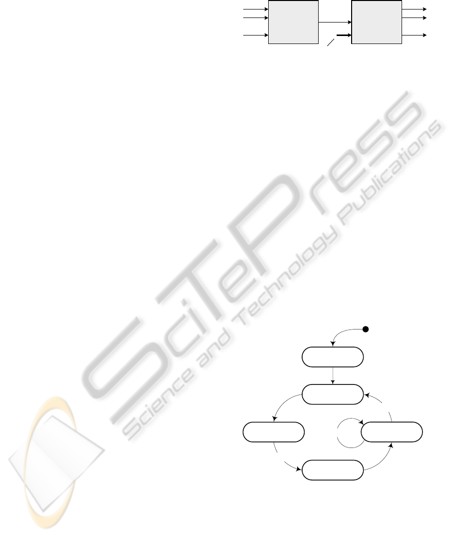
input signals to output signals (see Fig. 1).
SM
SG
..
..
..
..
Event
signals
Output
signals
Input signals
Control
step
Figure 1: State Machine and Signal Generator function
blocks.
The SM function block can be implemented
using a new version of the State Logic Controller
(SLC) design pattern originally introduced in
(Angelov et al., 2005). The SLC employs a data
structure that represents the state transition graph of
a Moore machine realizing the desired control
behaviour. It can be efficiently encoded as a table
containing binary decision diagrams that represent
the next-state mappings of various states s in the set
of states S, and the corresponding control steps, in
accordance with the state transition graph.
The next-state mapping of a state s is defined as
the subset Fs = {s’} involving those states that are
immediate successors of s. Hence, a state transition
graph can be symbolically represented by specifying
the next-state mappings of all states s ∈ S, whereby
the transition arcs are defined as tuples (s, s’ |
s’ ∈ F
s
) that are associated with the corresponding
transition events and event-priority symbols.
init
close_IV
open_EV
close_EV
pid_control
inspFlag
inspFlag
expFlag
s
1
s
2
s
3
s
4
s
5
1
2
s
0
Y
1
Y
2
Y
3
Y
4
Y
5
Figure 2: Medical Ventilator Control System: control actor
state machine.
This technique will be illustrated with a running
example, i.e. a control state machine encapsulated in
the Volume Control Ventilation (VCV) actor of a
Medical Ventilator Machine (Zhou et al., 2009), see
Fig. 2. Its state transition graph can be represented as
follows:
REUSABLE STATE MACHINE COMPONENTS FOR EMBEDDED CONTROL SYSTEMS
167

Fs
0
= s
1
/ Y
1
[c]
Fs
1
= s
2
/
Y
2
[c]
Fs
2
= s
3
/ Y
3
[c]
Fs
3
= s
4
/ Y
4
[e
1
], s
3
/ NOP [!e
1
]
Fs
4
= s
5
/ Y
5
[c]
Fs
5
= s
2
/ Y
2
[e
2
, 1], s
5
/ Y
5
[e
1
, 2],
s
5
/ NOP [!e
1
, !e
2
],
where s
0
denotes the initial pseudo-state, s
1
–
s
5
denote operational states; Y
1
– Y
5
denote the
corresponding control steps – initialization (init),
close inspiration valve (close_IV), open expiration
valve (open_EV) close expiration valve (close_EV),
PID control of inspiration valve (PID_control); e
1
and e
2
denote events represented by signals inspFlag
and expFlag respectively, and c denotes the default
clock event; bracketed expressions denote the
corresponding triggering events or <event – event-
priority> pairs (when necessary).
Next-state mappings can be conveniently
represented by means of binary decision diagrams,
as shown in Fig. 3 for the example state machine. In
these diagrams, circular nodes denote event signals
that have to be tested in order to determine the
current state/step to be executed from among the
subset of successors of the previous state/step. These
are tested in a predefined sequence that reflects the
priority of the corresponding transitions.
e
1
Y
1
Y
2
e
2
Y
3
Y
4
NOP
Y
5
Y
2
Y
5
NOP
e
1
1 0
01
1
0
FS
0
FS
1
FS
2
FS
3
FS
5
FS
4
s
0
s
2
s
3
s
4
s
5
s
3
s
2
s
5
s
5
s
1
Figure 3: Binary decision diagrams for next state (step)
mappings.
For example, it is possible to make a transition
from s
5
to either s
2
or s
5
, whereby the former
transition has higher importance, i.e. lower event
priority than the other one. That is encoded in the
BDD whereby the event signal e
2
is checked first
and the transition to s
2
– taken if e
2
is true; the
transition to s
5
will be taken only if e
2
is false and e
1
– true. In case neither of the event signals is present,
the parsing of the BDD ends up in a no-operation
(NOP) node, meaning that no transition is taken and
the previous state has to be maintained in the current
period without executing a control action.
Table 1: Step Sequence Table (the BDD Table).
Node
SuccTrue /
NextStateM
SuccFalse Mapping
0 Y
1
1
x
FS
0
1 Y
2
2
x
FS
1
2 Y
3
3
x
FS
2
3 e
1
4 5
FS
3
4 Y
4
6
x
5 NOP 3
x
6 Y
5
7
x
FS
4
7 e
2
1 8
FS
5
8 e
1
6 9
9 NOP 7
x
The binary decision diagrams of the next-state
mappings can be encoded in a Step Sequence Table,
(also called the BDD Table) as shown in Table 1. It
consists of the columns Node, successorTrue /
NextStateMapping and successorFalse, whereby the
first column contains symbols denoting BDD nodes,
and the other two columns – pointers to rows
containing the corresponding BDD elements. The
rows are grouped into segments containing the next-
state mappings of states s
0
– s
5
.
The Step Sequence Table can be interpreted
much in the same way as its graphical counterpart.
This can be done by a standard routine – a State
Machine Driver (SMD), which is activated
periodically by the host actor. Within each cycle, the
SMD processes the BDD segment containing the
successor states/steps of the state visited in the
previous cycle, in order to determine the current
state/step. If a state transition has taken place, the
control step index variable is updated accordingly,
and the associated Signal Generator function block
is subsequently invoked to execute the
corresponding control step. However, it is executed
only when the state is visited for the first time; it will
not be executed in subsequent cycles if the state is
maintained, unless a self-transition is explicitly
specified (execute-once semantics).
The above discussion is based on the assumption
that event signals are Boolean variables supplied by
external components, e.g. pre-processing function
ICINCO 2010 - 7th International Conference on Informatics in Control, Automation and Robotics
168

blocks such as digital and analogue signal
comparators, timers, event counters, etc. However,
this may result in relatively complex function block
networks modelling application actors. That problem
can be eliminated by executing pre-processing
operations as internal functions of the state machine
function block. In that case, the condition nodes of
the BDD may be interpreted as various types of
compare, event counting and timer operations whose
result is tested in order to make a branching decision
within the BDD.
Each node of the BDD is thus associated with an
operation that has to be executed by the State
Machine Driver when processing the node. To that
end, an operation code is used to specify the node
operation, e.g. a control step executed in a state
node. Likewise, it is necessary to specify operation
codes (or function pointers) for various Boolean test,
compare, and counter/timer operations executed in
condition-testing nodes of the BDD.
The BDD table of the state machine function
block can be encoded using records of the following
format:
BDD_Record = Operation, CondTest |
Operation, ControlStep;
Operation = CondOp1 |
... | CondOpk|
CtrlStepOp;
CondTest = Operand1, Operand2,
SuccessorTrue,
SuccessorFalse;
ControlStep = ControlStepIndex,
NextStateMapping;
where the Operation code specifies one of the
following node-processing operations:
Boolean operations
Compare Integer operations
Compare Real operations
Count Events operation
Control Step operation
In case of condition evaluation, the CondTest
part of the BDD record contains operand fields,
which are interpreted in the context of the executed
node-processing operation as follows:
Boolean operations use Operand1 and
Operand2 as pointers to the tested variable
locations.
Compare Integer and Compare Real operations
use Operand1 as a pointer to the first
compared variable and Operand2 – as a
pointer to the second compared variable or
constant.
The Count Events operation uses Operand1 as a
pointer to the counted event variable. The
initial value of the event counter and the event
counter itself are passed as parameters via the
Operand2 field.
The remaining two items of the condition-test
record are used to implement branching decisions, as
follows:
Successor1 is used as a pointer to the next line
to be processed if the test/compare/counter
operation returns True.
Successor0 is a pointer to the next line to be
processed if the test/compare/counter
operation returns False.
In case of control step execution, the Operation
field is accompanied by a ControlStep field
comprising:
ControlStepIndex – an index of the control step
that has to be executed in the current state. A
NOP encoding of the control step index
denotes no operation.
NextStateMapping – a pointer to the first line of
the corresponding next-state mapping.
The above operations are executed by the State
Machine Driver while processing binary decision
diagrams, as follows:
Boolean operations and compare operations are
implemented by means of C-library compare
routines, which return True or False depending on
the result.
The Count Events operation interprets Operand1
as a pointer to the input variable of the event
counter. If that is a NULL pointer, the event counter
is driven by the periodic timing events triggering the
host actor, and operates as a timer measuring time
intervals that are multiples of the actor period. The
initial value of the event counter and the counter
itself are passed as a pointer to a dedicated data
structure in the second operand field. The operation
returns False if [counter] != 0 after decrementing the
counter; if [counter] = 0, the operation re-initializes
the counter and returns True.
The control step index is supplied to the SG as an
input parameter used to invoke the corresponding
sequence of function blocks in order to generate the
required control signals. If the SM state in the
current cycle is the same as in the previous one
(NOP BDD node), a NOP control step index is
generated, in accordance with the adopted execute-
REUSABLE STATE MACHINE COMPONENTS FOR EMBEDDED CONTROL SYSTEMS
169

once semantics. However, a self loop may be used if
a control step has to be executed repeatedly in
successive periods (e.g. PID in state s
5
of Fig. 2).
The algorithm given below can be used to
implement a state machine driver for a reusable and
reconfigurable function block of class State
Machine:
void StateMachineDriver(void *FB)
{
// Restore execution history
BDD_Record *r = FB->tableRecord;
// Determine current step and update
// output
do {
// Condition-testing node?
if (r->operation != CTRL_STEP_OP)
{
if ((r->operation)(r->operand1,
r->operand2))
{ // True
r = r->successorTrue;
}
else { // False
r = r->successorFalse;
}
}
else {
// Control step node?
// Update control step index
FB->ctrlStepIndex =
r->ctrlStepIndex;
// Save execution history
if ( r->ctrlStepIndex != NOP )
FB->tableRecord =
r->nextStateMapping;
return; // Leave the driver
}
} while( TRUE );
}
The SM function block instance is invoked with
a pointer to an execution record of type
StateMachine denoted as FB, which contains
relevant data, such as output buffer for the control
step index variable as well as a tableRecord history
variable, i.e. a pointer to the first line of the next-
state mapping segment, to be processed during the
next activation of the SM function block.
3 SIGNAL GENERATOR
FUNCTION BLOCK
The Signal Generator is a composite function block
containing instances of function blocks that are to be
invoked within statically defined execution
schedules - control step (CS) sequences, in order to
generate the control signals associated with the
corresponding control steps.
To that end, the control step index generated by
the SM is used to access a table containing records
such as < CSsequenceStart, CSsequenceLength >,
where each line corresponds to one particular control
step. These two parameters are used to access a
Function Block Table (FBT) where each line
corresponds to a function block instance specified by
the record < FBfunction, FBinstance >.
In particular, the CSsequenceStart is used to
access a FBT record specifying the first function
block instance of a control step sequence, and
CSsequnceLength – the number of function block
instances that have to be invoked in order to execute
the control step. Hence, the FBT can be viewed as a
concatenation of control step sequences that are
specified by the corresponding sub-networks of the
function block network encapsulated in the Signal
Generator.
It is possible that several control steps generate
one and the same continuous control signal, e.g. a
control signal that is generated in both manual and
automatic mode of operation. In that case, a
Multiplexor FB shall be used, whereby different
Multiplexor functions are invoked to switch the
corresponding input signals to the multiplexor
output.
Discrete (on/off) control signals can be generated
by means of another kind of function block that may
be invoked within the Signal Generator – the
Discrete Control Function Block (DCFB). The
DCFB employs the concept of control memory
storing binary control words: a particular word is
accessed using the corresponding control step index,
and is subsequently stored in the DCFB output
buffer.
Discrete control signals can also be generated by
means of a digital multiplexor function block. In this
case, the control step index is used to select an input
binary word to be switched to the multiplexor output
in order to generate the corresponding on/off control
signals. This solution is preferable for applications
featuring a small number of discrete control steps, as
is the case with the example state machine of Fig. 1.
ICINCO 2010 - 7th International Conference on Informatics in Control, Automation and Robotics
170
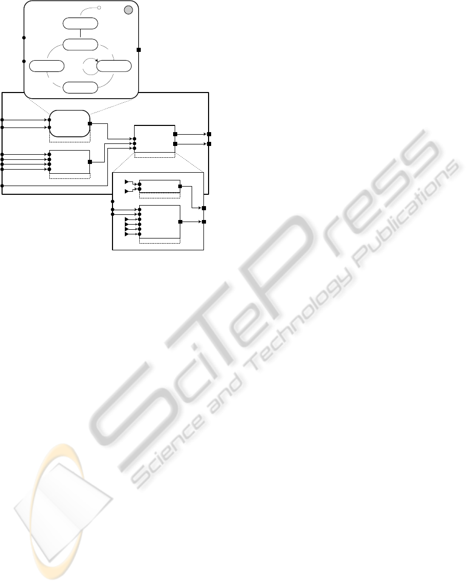
driver
driver
arith
step
setPoint
ctlX3.p1Flow
ctlX2.flowSet
ctlX1.inspFlag
ctlX2.I
ctlX2.E
ctlX2.respRate
State Machine
ctrlSM
ctrlSG
calcuSP
SPArithmetic
U16-float
Signal
Generator
expValveOutput
pidControlValue
init
close_IV
open_EV
close_EV
pid_control
inspFlag
inspFlag
expFlag
H
1
2
Ts
Kd
Ki
Kp
1
0
(EXPOPEN)
(EXPCLOSE)
setPoint
p1Flow
ctrlExpValve
2Multiplexer
U8-U8
ctrlInspValve
PID
float-float
action
expValveOutput
pidControlValue
ctlX1.expFlag
s
0
Figure 4: Control actor state machine implementation.
The Signal Generator of the example state
machine is shown in Fig. 4. It incorporates two
function block instances, i.e. a Multiplexor FB
instance generating on/off control signals for the
control steps open_EV and close_EV, and a PID FB
instance generating the signal pid_control and
close_IV. The PID function block encapsulates three
functions: initialize(), PID() and stop(). The first one
is invoked when executing the init control step and
the other two – when executing the control steps
pid_control and close_IV (by applying a zero
voltage to the inspiration valve of the ventilator).
The combination of state machine and signal
generator can be used to engineer sequential and
modal continuous control systems, as well as
systems generating continuous control signals in
some states and discrete on/off control signals in
other states, as shown in the example.
4 CONCLUSIONS
The paper presents a software design method for
embedded control applications, which employs two
types of reconfigurable component that can be used
to configure control system tasks (actors) – State
Machine and Signal Generator function blocks. The
State Machine function block realizes the reactive
(control flow) aspect of actor behaviour, in
separation from the transformational (data flow)
aspect, which is assigned to the Signal Generator.
The presented version of the State Machine
function block is capable of processing any kind of
input signal – Boolean, binary-coded or analogue in
order to compute Boolean event variables needed to
implicitly select the state to be activated, and to
explicitly select the control step to be executed in
that state. The index of the control step is then
indicated to the Signal Generator, in order to activate
the corresponding FB sequence used to generate the
corresponding control signals.
The State Machine has been implemented as a
reusable and reconfigurable function block using a
new BDD-based State Logic Controller design
pattern, resulting in a simple, yet powerful
component that can be combined with a
reconfigurable Signal Generator to efficiently
implement state machines of arbitrary complexity
for a broad range of sequential and hybrid control
applications.
REFERENCES
Samek, M., 2002. Practical Statecharts in C/C++:
Quantum Programming for Embedded Systems, CMP
Books.
John, K-H., Tiegelkamp, M., 2001. IEC61131-3:
Programming Industrial Automation Systems,
Springer.
Lewis, R., 2001. Modeling Control Systems Using IEC
61499, Institution of Electrical Engineers.
Wagner, F., Wolstenholme, P., 2003. Modeling and
Building Reliable, Re-usable Software. In 10th IEEE
International Conference and Workshop on the
Engineering of Computer-Based Systems. Huntsville,
USA.
Wang, S., Shin, K.G., 2002. Constructing Reconfigurable
Software for Machine Control Systems. In IEEE
Trans. on Robotics and Automation, vol. 18, No 4
Angelov, C., Sierszecki, K., Marian, N., 2005. Design
Models for Reusable and Reconfigurable State
Machines. In Lecture Notes in Computer Science, v.
3824, Springer
Angelov C., Ke, X., Guo Y., Sierszecki K., 2008.
Reconfigurable State Machine Components for
Embedded Applications. In SEAA 2008, 34th
EUROMICRO Conference on Software Engineering
and Advanced Applications, IEEE Computer Society
Zhou, F., Guan, W., Sierszecki, K., Angelov, C., 2009.
Component-Based Design of Software for Embedded
Control Systems: the Medical Ventilator Case Study.
In ICESS 2009, International Conference on
Embedded Software and Systems, IEEE Computer
Society
REUSABLE STATE MACHINE COMPONENTS FOR EMBEDDED CONTROL SYSTEMS
171
