
MODULATION-MODE ASSIGNMENT FOR SVD-ASSISTED
AND ITERATIVELY DETECTED DOWNLINK MULTIUSER MIMO
TRANSMISSION SCHEMES
Andreas Ahrens
Hochschule Wismar, University of Technology, Business and Design, Philipp-M¨uller-Straße 14, 23966 Wismar, Germany
C´esar Benavente-Peces
Universidad Polit´ecnica de Madrid, Ctra. Valencia km 7, 28031 Madrid, Spain
Keywords:
Multiple-input multiple-output system, Singular-value decomposition, Bit allocation, Power allocation, Wire-
less transmission, Multiuser transmission.
Abstract:
In this contribution we jointly optimize the number of multiple-input multiple-output (MIMO) layers and
the number of bits per symbol within an iteratively-detected multiuser MIMO downlink (DL) transmission
scheme under the constraint of a given fixed data throughput and integrity. Instead of treating all the users
jointly as in zero-forcing (ZF) multiuser transmission techniques, the investigated singular value decomposi-
tion (SVD) assisted DL multiuser MIMO system takes the individual user’s channel characteristics into ac-
count. In analogy to bit-interleaved coded irregular modulation, we introduce a MIMO-BICM scheme, where
different user-specific signal constellations and mapping arrangement were used within a single codeword.
Extrinsic information transfer (EXIT) charts are used for analyzing and optimizing the convergence behaviour
of the iterative demapping and decoding. Our results show that in order to achieve the best bit-error rate, not
necessarily all user-specific MIMO layers have to be activated.
1 INTRODUCTION
Bit-interleaved coded modulation (BICM) was de-
signed for bandwidth efficient transmission over
fading channels (Caire et al., 1998; Chindapol,
2001) and extended to bit-interleaved coded irreg-
ular modulation (BICIM) schemes by using differ-
ent signal constellations and mapping arrangements
within a single codeword, offering an improved link
adaptation capability and an increased design free-
dom(Schreckenbach and Bauch, 2006).
Since the capacity of multiple-input multiple-
output (MIMO) systems increases linearly with the
minimum number of antennas at both, the trans-
mitter as well as the receiver side, MIMO-BICM
schemes have attracted substantial attention (McKay
and Collings, 2005; M¨uller-Weinfurtner, 2002) and
can be considered as an essential part of increasing
both the achievable capacity and integrity of future
generations of wireless systems (K¨uhn, 2006; Zheng
and Tse, 2003).
However, their parameters have to be carefully op-
timized, especially in conjunction with adaptive mod-
ulation (Zhou et al., 2005). The well-known water-
filling technique is virtually synonymous with adap-
tive modulation and it is used for maximizing the
overall data rate (Krongold et al., 2000; Fischer and
Huber, 1996; Park and Lee, 2004). However, delay-
critical applications, such as voice or video transmis-
sion schemes, may require a certain fixed data rate.
For these fixed-rate applications it is desirable to de-
sign algorithms, which minimize the bit-error rate at
a given fixed data rate.
Single-user MIMO-BICM transmission schemes
for both non-frequency and frequency selective
MIMO channels have attracted a lot of attention and
reached a state of maturity (K¨uhn, 2006; Ahrens and
Benavente-Peces, 2009). By contrast, MIMO-aided
multiple-user systems require substantial further re-
search where both multiuser as well as multi-antenna
interferences have to be taken into account.
Considering the entirety of the antennas of all mo-
107
Ahrens A. and Benavente-Peces C. (2010).
MODULATION-MODE ASSIGNMENT FOR SVD-ASSISTED AND ITERATIVELY DETECTED DOWNLINK MULTIUSER MIMO TRANSMISSION
SCHEMES.
In Proceedings of the International Conference on Wireless Information Networks and Systems, pages 107-114
DOI: 10.5220/0002894001070114
Copyright
c
SciTePress

bile terminals at one end and the antennas of the base
station at the other end of the communication link,
state of the art interference cancellation is based on a
central signal processing unit, e. g. a central unit at
the base station, where joint detection can be applied
in the uplink (UL) and joint transmission in the down-
link (DL), respectively (Meurer et al., 2000; Choi and
Murch, 2004; Joham et al., 2005). Widely used lin-
ear preprocessing techniques such as Minimum Mean
Square Error or Zero Forcing (ZF) have attracted a lot
of research and have reached a state of maturity, too
(Choi and Murch, 2003).
Therefore, in this work a SVD-assisted downlink
(DL) multiuser MIMO-BICM system is considered,
which takes the individual user’s channel characteris-
tics into account rather than treating all users channels
jointly as in ZF multiuser transmission techniques
(Liu et al., 2008). The choice of the number of bits
per symbol and the number of activated MIMO layers
combined with powerful error correcting codes offer a
certain degree of design freedom (Ahrens and Lange,
2008). In addition to bit loading algorithms, in this
contribution the benefits of channel coding are also
investigated. The proposed iterative decoder struc-
tures employ symbol-by-symbolsoft-output decoding
based on the Bahl-Cocke-Jelinek-Raviv (BCJR) algo-
rithm and are analyzed under the constraint of a fixed
data throughput (Bahl et al., 1974). Against this back-
ground, the novel contribution of this paper is that we
jointly optimize the number of activated user-specific
MIMO layers and the number of bits per symbol com-
bined with powerful error correcting codes under the
constraint of a given fixed data throughput and in-
tegrity. Since the ”design-space” is large, a two-stage
optimization technique is considered. Firstly, the un-
coded spatial division multiplexing (SDM) MIMO
scheme is analyzed, investigating the allocation of
both the number of bits per modulated symbol and the
number of activated MIMO layers at a fixed data rate.
Secondly, the optimized uncoded system is extended
by incorporating bit-interleaved coded modulation us-
ing iterative detection (BICM-ID), whereby both the
uncoded as well as the coded systems are required to
support the same user data rate within the same band-
width.
The remaining part of this contribution is orga-
nized as follows: Section 2 introduces our system
model, while the proposed uncoded solutions are dis-
cussed in section 3. In section 4 the channel encoded
MIMO system is introduced. The associated perfor-
mance results are presented and interpreted in section
5. Finally, section 6 provides our concluding remarks.
2 MULTIUSER SYSTEM MODEL
The system model considered in this work consists of
a single base station (BS) supporting K mobile sta-
tions (MSs). The BS is equipped with n
T
transmit an-
tennas, while the kth (with k = 1,... , K) MS has n
Rk
receive antennas, i. e. the total number of receive an-
tennas including all K MSs is givenby n
R
=
∑
K
k=1
n
Rk
.
The (n
Rk
×1) user specific symbol vector c
k
to be
transmitted by the BS is given by
c
k
=
c
k,1
,c
k,2
,. ..,c
k,n
Rk
T
. (1)
The vector c
k
is preprocessed before its transmission
by multiplying it with the (n
T
×n
Rk
) DL preprocess-
ing matrix R
k
and results in the (n
T
×1) user-specific
transmit vector
s
k
= R
k
c
k
. (2)
After DL transmitter preprocessing, the n
T
-
component signal s transmitted by the BS to the
K MSs results in
s =
K
∑
k=1
s
k
= Rc , (3)
with the (n
T
×n
R
) preprocessing matrix
R = (R
1
,R
2
,. ..,R
K
) . (4)
In (3), the overall (n
R
×1) transmitted DL data vector
c combines all K DL transmit vectors c
k
(with k =
1,2,. .., K) and is given by
c =
c
T
1
,c
T
2
.. . ,c
T
K
T
. (5)
At the receiver side, the (n
Rk
×1) vector u
k
of the kth
MS results in
u
k
= H
k
s+ n
k
= H
k
Rc+ n
k
(6)
and can be expressed by
u
k
= H
k
R
k
c
k
+
K
∑
i=1,i6=k
H
k
R
i
c
i
+ n
k
, (7)
where the MSs received signals experience both
multi-user and multi-antenna interferences. In (6), the
(n
Rk
×n
T
) channel matrix H
k
connects the n
T
BS spe-
cific transmit antennas with the n
Rk
receive antennas
of the kth MS. It is assumed that the coefficients of
the (n
Rk
×n
T
) channel matrix H
k
are independent and
Rayleigh distributed with equal variance. The inter-
ference, which is introduced by the off-diagonal ele-
ments of the channel matrix H
k
, requires appropriate
signal processing strategies. A popular technique is
based on the SVD of the system matrix H
k
. Upon
carrying out the SVD of H
k
with n
T
≥ n
R
and assum-
ing that the rank of the matrix H
k
equals n
Rk
, i.e.,
rank(H
k
) = n
Rk
, we get
H
k
= U
k
·V
k
·D
H
k
, (8)
WINSYS 2010 - International Conference on Wireless Information Networks and Systems
108

with the (n
Rk
×n
Rk
) unitary matrix U
k
and the (n
T
×
n
T
) unitary matrix D
H
k
, respectively
1
. The (n
Rk
×n
T
)
diagonal matrix V
k
can be decomposed into a (n
Rk
×
n
Rk
) matrix V
ku
containing the non-zero square roots
of the eigenvalues of H
H
k
H
k
, i.e.,
V
ku
=
p
ξ
k,1
0 ··· 0
0
p
ξ
k,2
.
.
.
.
.
.
.
.
.
.
.
.
.
.
.
.
.
.
0 0 ···
p
ξ
k,n
Rk
, (9)
and a (n
Rk
×(n
T
−n
Rk
)) zero-matrix V
kn
according
to
V
k
= (V
ku
V
kn
) = (V
ku
0) . (10)
Additionally, the (n
T
×n
T
) unitary matrix D
k
can be
decomposed into a (n
T
×n
Rk
) matrix D
ku
constituted
by the eigenvectors corresponding to the non-zero
eigenvalues of H
H
k
H
k
and a (n
T
×(n
T
−n
Rk
)) matrix
D
kn
constituted by the eigenvectors corresponding to
the zero eigenvalues of H
H
k
H
k
. The decomposition of
the matrix D
H
k
results in
D
H
k
=
D
H
ku
D
H
kn
!
. (11)
Finally, the received downlink signal u
k
of the kth MS
may be expressed as
u
k
= U
k
V
ku
D
H
ku
Rc+ n
k
, (12)
with the vector n
k
of the additive, white Gaussian
noise (AWGN). Taking all MSs received DL signals
u
k
into account, the (n
R
×1) receive vector results in
u =
u
T
1
,u
T
2
,. ..,u
T
K
T
. (13)
Then, the overall DL signal vector u including the re-
ceived signals of all K MSs can be expressed by
u = UV
u
D
H
u
Rc+ n , (14)
with the overall (n
R
×1) noise vector
n =
n
T
1
,n
T
2
,. ..,n
T
K
T
, (15)
the (n
R
×n
R
) block diagonal matrix U
U =
U
1
0 ··· 0
0 U
2
.
.
.
.
.
.
.
.
.
.
.
.
.
.
.
.
.
.
0 0 ··· U
K
, (16)
1
The transpose and conjugate transpose (Hermitian) of
D
k
are denoted by D
T
k
and D
H
k
, respectively.
the (n
R
×n
R
) block diagonal matrix V
u
V
u
=
V
1u
0 ··· 0
0 V
2u
.
.
.
.
.
.
.
.
.
.
.
.
.
.
.
.
.
.
0 0 ··· V
Ku
, (17)
and the (n
T
×n
R
) matrix D
u
which is given by
D
u
= (D
1u
,D
2u
,. ..,D
Ku
) . (18)
In order to suppress the DL multi-user interferences
(MUI) perfectly, the DL preprocessing matrix R has
to be designed to satisfy the following condition
D
H
u
R = P , (19)
with the real-valued (n
R
×n
R
) diagonal matrix P tak-
ing the transmit-power constraint into account. In or-
der to satisfy (19), R can be defined as follows
R = D
u
D
H
u
D
u
−1
P . (20)
Taking the ZF design criterion for the DL preprocess-
ing matrix into account, the matrix P simplifies to an
(n
R
×n
R
) diagonal matrix, i. e. P =
p
βI
n
R
×n
R
, with
the parameter
p
β taking the transmit-power con-
straint into account. When taking the DL preprocess-
ing matrix, defined in (20), into account, the overall
received vector of all K MSs, defined in (14), can be
simplified to
u = UV
u
Pc+ n . (21)
Therein, the (n
R
× n
R
) block diagonal matrix P is
given by
P =
P
1
0 ··· 0
0 P
2
.
.
.
.
.
.
.
.
.
.
.
.
.
.
.
.
.
.
0 0 ··· P
K
. (22)
In (21), the user-specific (n
Rk
×1) vector u
k
can be
expressed as
u
k
= U
k
V
ku
P
k
c
k
+ n
k
, (23)
with the user-specific (n
Rk
×n
Rk
) power allocation
matrix
P
k
=
√
p
k,1
0 ··· 0
0
√
p
k,2
.
.
.
.
.
.
.
.
.
.
.
.
.
.
.
.
.
.
0 0 ···
√
p
k,n
Rk
. (24)
As long as the transmit power is uniformly distributed
over the number of activated MIMO layers, the ma-
trix P
k
simplifies to P
k
=
p
βI
n
Rk
×n
Rk
. After postpro-
cessing of the received signal vectors u
k
with the cor-
responding unitary matrix U
H
k
, the user-specific deci-
sion variables result with U
H
k
n
k
= w
k
in
y
k
= U
H
k
u
k
= V
ku
P
k
c
k
+ w
k
, (25)
MODULATION-MODE ASSIGNMENT FOR SVD-ASSISTED AND ITERATIVELY DETECTED DOWNLINK
MULTIUSER MIMO TRANSMISSION SCHEMES
109
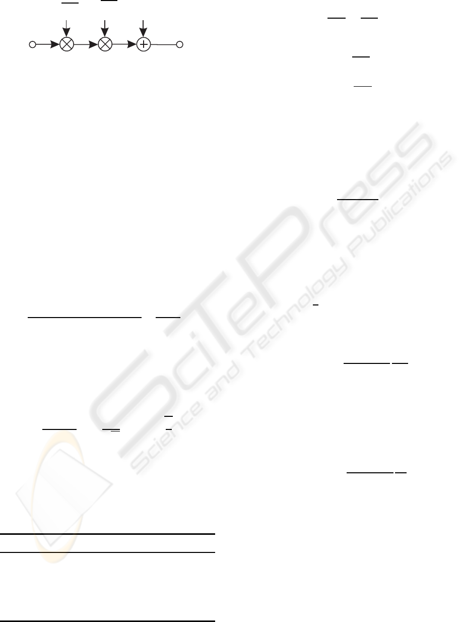
c
(m)
k,ℓ
y
(m)
k,ℓ
w
(m)
k,ℓ
q
ξ
(m)
k,ℓ
q
p
(m)
k,ℓ
Figure 1: Resulting kth user-specific system model per
MIMO layer ℓ (with ℓ = 1, 2,.. ., n
Rk
) and per transmitted
symbol block m.
or alternatively with U
H
n = w in
y = U
H
u = V
u
Pc+ w , (26)
where interferences between the different antenna
data streams as well as MUI imposed by the other
users are avoided. The resulting system model is de-
picted in Figure 1
3 QUALITY CRITERIA
In general, the user-specific quality of data transmis-
sion can be informally assessed by using the signal-
to-noise ratio (SNR) at the detector’s input defined by
the half vertical eye opening and the noise power per
quadrature component according to
ρ =
(Half vertical eye opening)
2
Noise Power
=
(U
A
)
2
(U
R
)
2
, (27)
which is often used as a quality parameter (Ahrens
and Lange, 2008). The relationship between the
signal-to-noise ratio ρ = U
2
A
/U
2
R
and the bit-error
probability evaluated for AWGN channels and M-ary
Quadrature Amplitude Modulation (QAM) is given
by (Proakis, 2000)
P
BER
=
2
log
2
(M)
1−
1
√
M
erfc
r
ρ
2
. (28)
When applying the proposed system structure for the
kth user, depicted in Figure 1, the applied signal pro-
cessing leads to different eye openings per activated
MIMO layer ℓ (with ℓ = 1,2,..., L and L ≤ n
Rk
de-
scribing the number of activated user-specific MIMO
Table 1: Investigated user-specific transmission modes.
throughput layer 1 layer 2 layer 3 layer 4
8 bit/s/Hz 256 0 0 0
8 bit/s/Hz 64 4 0 0
8 bit/s/Hz 16 16 0 0
8 bit/s/Hz 16 4 4 0
8 bit/s/Hz 4 4 4 4
layers) and per transmitted symbol block m according
to
U
(ℓ,m)
Ak
=
q
p
(m)
k,ℓ
·
q
ξ
(m)
k,ℓ
·U
(ℓ)
sk
, (29)
where U
(ℓ)
sk
denotes the half-level transmit amplitude
assuming M
ℓ
-ary QAM,
q
ξ
(m)
k,ℓ
represents the cor-
responding positive square roots of the eigenvalues
of the matrix H
H
k
H
k
and
q
p
(m)
k,ℓ
represents the cor-
responding power allocation weighting parameters
(Figure 1). Together with the noise power per quadra-
ture component, introduced by the additive, white
Gaussian noise (AWGN) vector w
k
= U
H
k
n
k
in (25),
the kth user-specific SNR per MIMO layer ℓ at the
time m becomes
ρ
(ℓ,m)
k
=
U
(ℓ,m)
Ak
2
U
2
R
. (30)
Using the parallel transmission over L MIMO lay-
ers, the overall mean user-specific transmit power be-
comes P
sk
=
∑
L
ℓ=1
P
(ℓ)
sk
. Considering QAM constel-
lations, the average user-specific transmit power P
(ℓ)
sk
per MIMO layer ℓ may be expressed as (Proakis,
2000)
P
(ℓ)
sk
=
2
3
U
(ℓ)
sk
2
(M
kℓ
−1) . (31)
Combining (30) and (31) together with (29), the layer-
specific SNR at the time m results in
ρ
(ℓ,m)
k
= p
(m)
k,ℓ
ξ
(m)
k,ℓ
3
2(M
kℓ
−1)
P
(ℓ)
sk
U
2
R
. (32)
Assuming that the user-specific transmit power is
uniformly distributed over the number of activated
MIMO layers, i. e., P
(ℓ)
sk
= P
sk
/L, the layer-specific
signal-to-noise ratio at the time m, defined in (32),
results with the ratio of symbol energy to noise power
spectral density E
s
/N
0
= P
sk
/(2U
2
R
) in
ρ
(ℓ,m)
k
= p
(m)
k,ℓ
ξ
(m)
k,ℓ
3
L(M
kℓ
−1)
E
s
N
0
. (33)
In order to transmit at a fixed data rate while main-
taining the best possible integrity, i.e., bit-error rate,
an appropriate number of user-specific MIMO layers
has to be used, which depends on the specific trans-
mission mode, as detailed in Table 1 for the exemplar-
ily investigated two-user multiuser-system (n
Rk
= 4
(with k = 1,2), K = 2,n
R
= n
T
= 8). An optimized
adaptive scheme would now use the particular trans-
mission modes, e. g., by using bit auction procedures
(Wong et al., 1999), that results in the lowest BER for
each SDM MIMO data vector. However, this would
lead to a high signaling overhead. Therefore, in order
WINSYS 2010 - International Conference on Wireless Information Networks and Systems
110
i
b
˜
b
c
k,1
c
k,2
c
k,L
encoder
∏
Mapper
Mapper
Mapper
MUX and Buffer
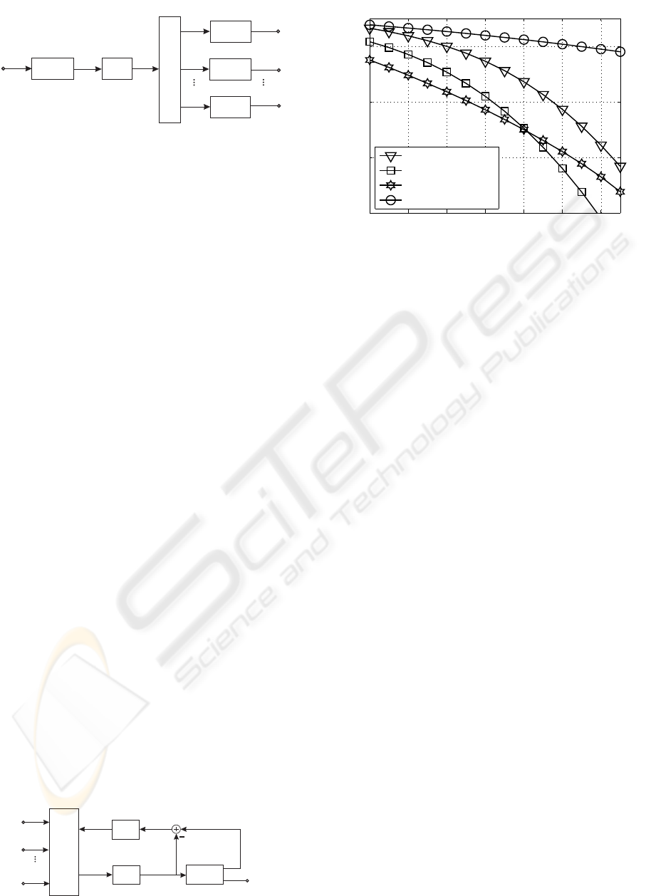
Figure 2: The channel-encoded kth user-specific MIMO
transmitter structure.
to avoid any signalling overhead, fixed transmission
modes are used in this contribution regardless of the
channel quality.
4 CHANNEL-ENCODED MIMO
SYSTEM
The channel encoded user-specific transmitter struc-
ture is depicted in Figure 2. The encoder employs a
half-rate nonrecursive, non-systematic convolutional
(NSC) code using the generator polynomials (7,5) in
octal notation. The uncoded information is organized
in blocks of N
i
bits, consisting of at least 3000 bits,
depending on the specific QAM constellation used.
Each data block i is encoded and results in the block
b consisting of N
b
= 2N
i
+ 4 encoded bits, including
2 termination bits. The encoded bits are interleaved
using a random interleaver and stored in the vector
˜
b. The encoded and interleaved bits are then mapped
to the MIMO layers. The task of the multiplexer and
buffer block of Figure 2 is to divide the user-specific
vector of encoded and interleaved information bits
˜
b
into subvectors according to the chosen transmission
mode (Table 1). The individual user-specific binary
data vectors are then mapped to the QAM symbols
c
k,ℓ
according to the specific mapper used. The it-
erative demodulator structure is shown in Figure 3
(Ahrens et al., 2008). When using the iteration in-
dex ν, the first iteration of ν = 1 commences with
the soft-demapper delivering the N
b
log-likelihood
ratios (LLRs) L
(ν=1)
2
(
˜
b) of the encoded and inter-
leaved information bits, whose de-interleaved version
L
(ν=1)
a,1
(b) represents the input of the convolutionalde-
coder as depicted in Figure 3 (Bahl et al., 1974; K¨uhn,
2006). This channel decoder provides the estimates
y
k,1
y
k,2
y
k,L
Soft Demapper
L
(ν)
2
(
˜
b)
∏
−1
∏
L
(ν)
a,1
(b)
decoder
L
(ν)
1
(i)
L
(ν)
1
(b)
L
(ν−1)
e,1
(b)
L
(ν)
a,2
(
˜
b)
Figure 3: Iterative demodulator structure.
12 14 16 18 20 22 24
10
−8
10
−6
10
−4
10
−2
10 ·log
10
(E
s
/N
0
) (in dB) →
bit-error rate →
(256,0,0, 0) QAM
(64,4,0,0) QAM
(16,4,4,0) QAM
(4,4,4,4) QAM
Figure 4: Uncoded BERs when using the MIMO configura-
tions introduced in Table 1 and transmitting 8 bit/s/Hz over
non-frequency selective uncorrelated Rayleigh channels.
L
(ν=1)
1
(i) of the original uncoded information bits as
well as the LLRs of the N
b
NSC-encoded bits in the
form of
L
(ν=1)
1
(b) = L
(ν=1)
a,1
(b) + L
(ν=1)
e,1
(b) . (34)
As seen in Figure 3 and (34), the LLRs of the NSC-
encoded bits consist of the receiver’s input signal it-
self plus the extrinsic information L
(ν=1)
e,1
(b), which
is generated by subtracting L
(ν=1)
a,1
(b) from L
(ν=1)
1
(b).
The appropriately ordered, i.e. interleaved extrinsic
LLRs are fed back as a priori information L
(ν=2)
a,2
(
˜
b)
to the soft demapper of Figure 3 for the second itera-
tion.
5 RESULTS
Assuming predefined QAM constellation sizes, a
fixed total throughput can be guaranteed for each
SDM MIMO block regardless of the channel quality.
5.1 Single-user System
Considering a non-frequency selective single-user
SDM MIMO link (K = 1) composed of n
T
= 4 trans-
mit and n
R
= 4 receive antennas, the corresponding
calculated BER curves are depicted in Figure 4 for the
different QAM constellation sizes and MIMO con-
figurations of Table 1, when transmitting at a band-
width efficiency of 8 bit/s/Hz, assuming a Nyquist
roll-off factor of 0.5. Assuming a uniform distribu-
tion of the transmit power over the number of acti-
vated MIMO layers, it turns out that not all MIMO
layers have to be activated in order to achieve the best
BERs. However, it is worth noting that the lowest
MODULATION-MODE ASSIGNMENT FOR SVD-ASSISTED AND ITERATIVELY DETECTED DOWNLINK
MULTIUSER MIMO TRANSMISSION SCHEMES
111

Table 2: Probability of choosing specific transmission
modes (K = 1) at a fixed data rate by using optimal bit-
loading (10·log
10
(E
s
/N
0
) = 10 dB).
mode (64,4, 0,0) (16,16,0,0) (16,4,4, 0) (4,4,4,4)
pdf 0.0116 0.2504 0.7373 0.0008
BERs can only be achieved by using bit auction pro-
cedures leading to a high signalling overhead (Wong
et al., 1999). Analyzing the probability of choosing a
specific transmission mode by using optimal bitload-
ing, as depicted in Table 2, it turns out that only an
appropriate number of MIMO layers has to be acti-
vated, e. g., the (16,4,4,0) QAM configuration. The
results, obtained by using bit auction procedures jus-
tify the choice of fixed transmission modes regardless
of the channel quality as investigated in the contribu-
tion. Besides this, the joint optimization of the num-
ber of activated MIMO layers as well as the number
of bits per symbol was found to be effective at high
SNRs. However, iterative receivers are able to work
in a much lower SNR region. Therefore it would be
interesting to see how the design criteria change when
coding is added to the transmission system.
Using the half-rate, constraint-length K
cl
= 3 NSC
code with the generator polynomials of (7,5) in octal
notation, the BER performance is analyzed for an ef-
fective throughput of 4 bit/s/Hz based on the best un-
coded schemes of Table 1. In addition to the number
of bits per symbol and the number of activated MIMO
layers, the achievable performance of the iterative de-
coder is substantially affected by the specific mapping
of the bits to both the QAM symbols as well
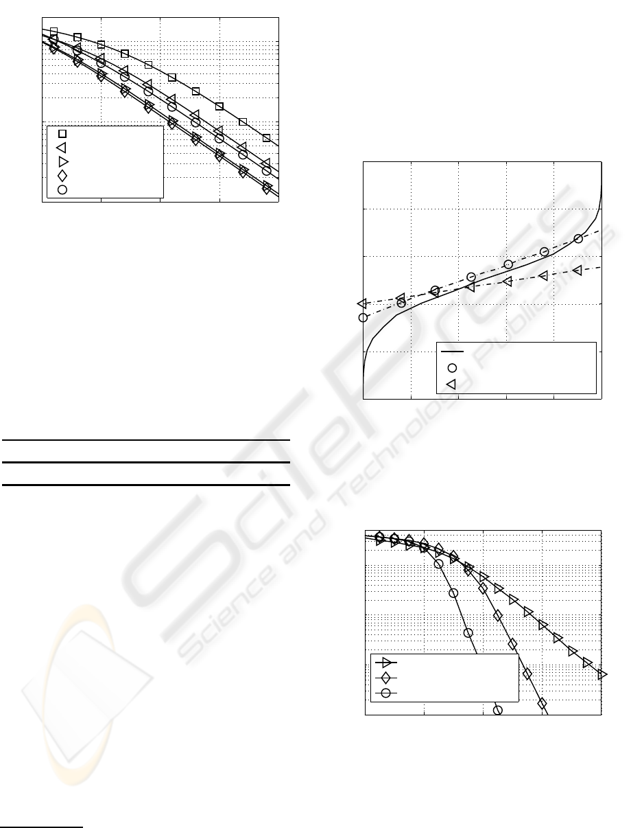
0 0.2 0.4 0.6 0.8 1
0
0.2
0.4
0.6
0.8
1
extrinsic demapper output →
extrinsic decoder output →
NSC code
anti-Gray/anti-Gray/anti-Gray
anti-Gray/Gray/Gray
Gray/anti-Gray/anti-Gray
Gray/Gray/Gray
Figure 5: EXIT chart for an effective throughput of
4 bit/s/Hz and the (16,4,4,0) QAM constellation at
10 log
10
(E
s
/N
0
) = 2 dB.
1 2 3 4 5 6 7
10
−3
10
−2
10
−1
10 ·log
10
(E
s
/N
0
) (in dB) →
bit-error rate →
(4,4,0,0) QAM, uncoded
(16,4,4,0) QAM, Gray, 3 Iter.
(16,4,4,0) QAM, anti-Gray, 3 Iter.
(16,4,4,0) QAM, anti-Gray, 10 Iter.
Figure 6: BERs assuming Gray or anti-Gray mapping
schemes on all activated MIMO layers for an effective user
throughput of 4 bit/s/Hz.
as to the MIMO layers. While the employment of the
classic Gray-mapping is appropriate in the absence of
a priori information, the availability of a priori in-
formation in iterative receivers requires an exhaustive
search for finding the best non-Gray – synonymously
also referred to anti-Gray – mapping scheme (Chin-
dapol, 2001).
A mapping scheme optimized for perfect a pri-
ori information has usually a poor performance, when
there is no a priori information. However, when ap-
plying iterative demapping and decoding, large gains
can be achieved as long as the reliability of the a pri-
ori information increases upon increasing the num-
ber of iterations. As depicted in Figure 5, the max-
imum iteration gain can only be guaranteed, if anti-
Gray mapping is used on all activated MIMO layers.
At the first iteration, using anti-Gray mapping on all
MIMO layers results in a lower extrinsic demapper
output, compared with layer-specific or Gray map-
ping schemes (e.g. layer 1: anti-Gray, layer 2 and
3: Gray). However, anti-Gray mapping on all MIMO
layers outperforms layer-specific mapping strategies
for high a priori information. Furthermore, observed
by comparing the EXIT chart results of Figure 5,
the overall performance is strongly influenced by
the most susceptible MIMO layer, which is here the
MIMO layer transmitting 4 bit/s/Hz. Finally, the BER
performance is characterized in Figure 6 based on the
best uncoded schemes of Table 1. The information
word length is 3000 bits and a random interleaver is
applied. The influence of the Gray versus anti-Gray
mapping is clearly visible in Figure 6.
Further improvements in terms of the BER are
possible by using unequal powerallocation. However,
as shown in (Ahrens and Lange, 2008) and (Ahrens
and Benavente-Peces, 2009), unequal power alloca-
tion in combination with the joint optimization of the
WINSYS 2010 - International Conference on Wireless Information Networks and Systems
112
10 15 20 25 30
10
−3
10
−2
10
−1
10 ·log
10
(E
s
/N
0
) (in dB) →
bit-error rate →
(256,0, 0, 0) QAM
(64,4, 0, 0) QAM
(16,16, 0, 0) QAM
(16,4, 4, 0) QAM
(4,4,4, 4) QAM
Figure 7: User-specific BERs when using the transmission
modes introduced in Table 1 and transmitting 8 bit/s/Hz
over non-frequency selective channels.
number of activated MIMO layers as well as the num-
ber of bits per symbol was found to be effective at
high SNRs. However, iterative receivers are able to
work in a much lower SNR region, where a power
allocation scheme was found to be inefficient.
Table 3: Probability of choosing user-specific transmission
modes (K = 2) at a fixed data rate by using optimal bitload-
ing (10·log
10
(E
s
/N
0
) = 10 dB).
mode (64,4, 0,0) (16,16,0,0) (16,4,4, 0) (4,4,4,4)
pdf 0 0.0102 0.9524 0.0374
5.2 Multiuser System
The parameters of the analyzed two-users MIMO sys-
tem are chosen as follows
2
: P
sk
= 1V
2
, n
Rk
= 4 (with
k = 1,2), K = 2,n
R
= n
T
= 8. The obtained user-
specific BER curves are depicted in Figure 7 for the
different QAM constellation sizes and MIMO config-
urations of Table 1. Assuming a uniform distribution
of the transmit power over the number of activated
MIMO layers, it still turns out that not all MIMO
layers have to be activated in order to achieve the
best BERs. This can still be confirmed by analyz-
ing the probability of choosing user-specific transmis-
sion modes within the multiuser DL MIMO system by
using optimal bitloading (Wong et al., 1999), as de-
picted in Table 3. However, based on the higher total
throughput within the given bandwidth compared to
the single-user system, the gap between the different
transmission modes becomes smaller.
2
In this contribution a power with the dimension
(voltage)
2
(in V
2
) is used. At a real constant resistor this
value is proportional to the physical power (in W).
Using the half-rate, constraint-length K
cl
= 3 NSC
code and comparing the EXIT chart results of Fig-
ure 8, the overall performance is still strongly influ-
enced by the number of activated MIMO layers, sug-
gesting that at low SNR not all MIMO layers has to
be activated in order to guarantee an efficient infor-
mation exchange between the soft-demapper and the
corresponding decoder. The user-specific BER per-
0 0.2 0.4 0.6 0.8 1
0
0.2
0.4
0.6
0.8
1
extrinsic demapper output →
extrinsic decoder output →
NSC code
(16,4,4, 0) QAM
(4,4, 4,4) QAM
Figure 8: User-specific EXIT chart for an effective through-
put of 4 bit/s/Hz when using anti-Gray mapping on all acti-
vated MIMO layers (10 log
10
(E
s
/N
0
) = 7 dB) and the half-
rate NSC code with the generator polynomials of (7,5) in
octal notation.
4 6 8 10 12
10
−4
10
−3
10
−2
10
−1
10 ·log
10
(E
s
/N
0
) (in dB) →
bit-error rate →
(4,4,4,4) QAM, 3 Iter.
(16,4,4,0) QAM, 3 Iter.
(16,4,4,0) QAM, 10 Iter.
Figure 9: User-specific BERs for an effective throughput
of 4 bit/s/Hz and anti-Gray mapping in combination with
different transmission modes and the half-rate NSC code
with the generator polynomials of (7,5) in octal notation.
formance is given in Figure 9 and underlines that in
order to minimize the overall BER not necessarily all
user-specific MIMO layers has to be activated.
MODULATION-MODE ASSIGNMENT FOR SVD-ASSISTED AND ITERATIVELY DETECTED DOWNLINK
MULTIUSER MIMO TRANSMISSION SCHEMES
113

6 CONCLUSIONS
In analogy to BICIM, we introduced a multi-user
MIMO-BICM scheme, where different user-specific
signal constellations and mappings were used within
a single codeword. The proposed system includes an
adaptation of the transmit parameters. EXIT charts
are used for analysing and optimizing the conver-
gence behaviour of iterative demapping and decoding.
The choice of the number of bits per symbol and
the number of MIMO layers combined with power-
ful error correcting codes substantially affects the per-
formance of a MIMO system, suggesting that not all
MIMO layers have to be activated in order to achieve
the best BERs. Here, anti-Gray mapping on all acti-
vated MIMO layers seems to be a promising solution
for minimizing the overall BER characteristic.
REFERENCES
Ahrens, A. and Benavente-Peces, C. (2009). Modulation-
Mode and Power Assignment for Broadband MIMO-
BICM Schemes. In IEEE 20th Personal, Indoor and
Mobile Radio Communications Symposium (PIMRC),
Tokio (Japan).
Ahrens, A. and Lange, C. (2008). Modulation-Mode and
Power Assignment in SVD-equalized MIMO Sys-
tems. Facta Universitatis (Series Electronics and En-
ergetics), 21(2):167–181.
Ahrens, A., Ng, S. X., K¨uhn, V., and Hanzo, L. (2008).
Modulation-Mode Assignment for SVD-Aided and
BICM-Assisted Spatial Division Multiplexing. Phys-
ical Communications (PHYCOM), 1(1):60–66.
Bahl, L. R., Cocke, J., Jelinek, F., and Raviv, J. (1974).
Optimal Decoding of Linear Codes for Minimizing
Symbol Error Rate. IEEE Transactions on Informa-
tion Theory, 20(3):284–287.
Caire, G., Taricco, G., and Biglieri, E. (1998). Bit-
Interleaved Coded Modulation. IEEE Transactions on
Information Theory, 44(3):927–946.
Chindapol, A. Ritcey, J. A. (2001). Design, Analysis, and
Performance Evaluation for BICM-ID with square
QAM Constellations in Rayleigh Fading Channels.
IEEE Journal on Selected Areas in Communications,
19(5):944–957.
Choi, R. L. and Murch, R. D. (2003). New Transmit
Schemes and Simplified Receivers for MIMO Wire-
less Communication Systems. IEEE Transactions on
Wireless Communications, 2(6):1217–1230.
Choi, R. L. and Murch, R. D. (2004). A Transmit Prepro-
cessing Technique for Multiuser MIMO Systems us-
ing a Decomposition Approach. IEEE Transactions
on Wireless Communications, 3(1):20–24.
Fischer, R. F. H. and Huber, J. B. (1996). A New
Loading Algorithm for Discrete Multitone Modula-
tion. In IEEE Global Telecommunications Conference
(GLOBECOM), pages 724–728, London.
Joham, M., Utschick, W., and Nossek, J. A. (2005). Lin-
ear Transmit Processing in MIMO Communications
Systems. IEEE Transactions on Signal Processing,
53(8):2700–2712.
Krongold, B. S., Ramchandran, K., and Jones, D. L.
(2000). Computationally Efficient Optimal Power Al-
location Algorithms for Multicarrier Communications
Systems. IEEE Transactions on Communications,
48(1):23–27.
K¨uhn, V. (2006). Wireless Communications over MIMO
Channels – Applications to CDMA and Multiple An-
tenna Systems. Wiley, Chichester.
Liu, W., Yang, L. L., and Hanzo, L. (2008). SVD Assisted
Joint Transmitter and Receiver Design for the Down-
link of MIMO Systems. In IEEE 68th Vehicular Tech-
nology Conference (VTC), pages 1–5, Calgary.
McKay, M. R. and Collings, I. B. (2005). Capacity
and Performance of MIMO-BICM with Zero-Forcing
Receivers. IEEE Transactions on Communications,
53(1):74– 83.
Meurer, M., Baier, P. W., Weber, T., Lu, Y., and Papathanas-
siou, A. (2000). Joint Transmission: An Advanta-
geous Downlink Concept for CDMA Mobile Radio
Systems using Time Division Duplexing. Electronics
Letters, 36(10):900–901.
M¨uller-Weinfurtner, S. H. (2002). Coding Approaches for
Multiple Antenna Transmission in Fast Fading and
OFDM. IEEE Transactions on Signal Processing,
50(10):2442–2450.
Park, C. S. and Lee, K. B. (2004). Transmit Power Alloca-
tion for BER Performance Improvement in Multicar-
rier Systems. IEEE Transactions on Communications,
52(10):1658–1663.
Proakis, J. G. (2000). Digital Communications. McGraw-
Hill, Boston.
Schreckenbach, F. and Bauch, G. (2006). Bit-Interleaved
Coded Irregular Modulation. European Transactions
on Telecommunications, 17(2):269–282.
Wong, C. Y., Cheng, R. S., Letaief, K. B., and Murch, R. D.
(1999). Multiuser OFDM with Adaptive Subcarrier,
Bit, and Power Allocation. IEEE Journal on Selected
Areas in Communications, 17(10):1747–1758.
Zheng, L. and Tse, D. N. T. (2003). Diversity and
Multiplexing: A Fundamental Tradeoff in Multiple-
Antenna Channels. IEEE Transactions on Information
Theory, 49(5):1073–1096.
Zhou, Z., Vucetic, B., Dohler, M., and Li, Y. (2005). MIMO
Systems with Adaptive Modulation. IEEE Transac-
tions on Vehicular Technology, 54(5):1073–1096.
WINSYS 2010 - International Conference on Wireless Information Networks and Systems
114
