
Generation Mechanisms in Graphical Template
Language
Elina Kalnina
*
, Audris Kalnins, Edgars Celms, Agris Sostaks
*
and Janis Iraids
*
University of Latvia, IMCS, Raina bulvaris 29, LV-1459 Riga, Latvia
Abstract. Textual models in MDD typically are generated in their concrete
syntax using a template based language. On the contrary, graphical models as a
rule are generated in abstract syntax and then visualized, which is not very
efficient for complicated languages. The paper discusses a case of template
based generation of graphical models in a concrete syntax. We apply this
approach to generation of programs in MOLA transformation language using
the Template MOLA language. A novel idea of merge mechanism in MOLA
templates is proposed which permits to obtain the required structure of
generated models in an easy way.
1 Introduction
Model driven development (MDD) has become one of the most popular technologies
for software development, with model transformations as the key support feature.
MDD can be naturally applied also to transformation development itself. This means
that transformations are used to create transformations. Typically such
transformations are called Higher-Order Transformations (HOT). In this paper we
want to discuss just this aspect of MDD and template based languages for it.
There are many template based model to text languages, for example, JET [1],
mof2text [2], and other. The basic application of these languages is to create code (in
Java, XML, etc.) from the PSM model in the standard MDD process. These languages
typically contain facilities to navigate the given model according to its metamodel.
However, the main advantage of these languages is the possibility to define the text
fragment to be generated by the given rule as a textual template in the relevant
concrete syntax.
Graphical languages are also used in software development. There are cases when
we want to generate code (in fact, diagrams) for these graphical languages. Code
generation for graphical languages is significantly less examined. The universal
approach would be to create code in graphical languages using abstract syntax of the
language and then generate some kind of visualisation. This approach works well in
simple cases e.g., when one type of UML diagrams is to be generated from another.
*
Research is partially supported by ESF projects 2009/0138/1DP/1.1.2.1.2/09/IPIA/VIAA/004
and 2009/0162/1DP/1.1.2.1.1/09/IPIA/VIAA/004
Kalnina E., Kalnins A., Celms E., Sostaks A. and Iraids J. (2010).
Generation Mechanisms in Graphical Template Language.
In Proceedings of the 2nd International Workshop on Model-Driven Architecture and Modeling Theory-Driven Development, pages 43-52
DOI: 10.5220/0003043900430052
Copyright
c
SciTePress

However, for more sophisticated languages such as transformation languages this
approach turns out to be too complicated in practice, frequently because of significant
differences between the abstract syntax (domain metamodel) and graphical
presentation. A natural question arises: whether template mechanisms so widely used
for text synthesis would not be more appropriate? They would permit to use the
concrete syntax as the basis. And further, how can we adapt these template
mechanisms to graphical languages?
To create programs in a graphical language using concrete syntax it must be
possible to describe the creation of relevant graphical elements. So we need a
graphical notation for elements to be created. We have also to describe the synthesis
logic. It means we should be able to use these two-dimensional (2D) graphical
elements in generation loops, branching etc. There are also some essential differences
in template based generation of concrete syntax between textual and graphical
languages. Text in a textual language is being generated as a single string with one
active point where the text is being extended. Unless we need to update the already
generated part there is no necessity to reference other points in the generated part. On
the contrary, generation of a 2D diagram (more precisely, a graph) frequently requires
a convenient access to the generated part in order to add new edges to it. Another
difference is that in a textual language any template element can be surrounded by a
generation time iterator while in graphical language there is a natural granularity of
elements which can be iterated during generation. All this requires some specific
solution for template based generation of graphical languages. We propose a merge
mechanism as a solution.
In this paper we discuss the graphical language Template MOLA for MOLA
transformation synthesis. Basic principles of this language and typical use cases have
been described in [3]. In this paper we introduce the merge mechanisms in Template
MOLA to achieve a flexible generation of MOLA code. They permit to obtain a well
structured readable code instead of spaghetti code, thus making it close to handwritten
result. Some advanced features of Template MOLA are also described.
We start the paper with short description of MOLA and Template MOLA in
section 2. Section 3 describes motivation for the merge mechanism introduced in
Template MOLA in section 4. We complete the paper with related work in section 5
and conclusions sketching how the approach could be used in general for graphical
language synthesis.
2 Template MOLA Description
The Template MOLA language is based on model transformation language MOLA.
Template MOLA is used for easy generation of transformations in MOLA from
various input models – as a substitute for the classical HOT approach. All MOLA
elements are retained in Template MOLA. Additionally special template elements for
easy MOLA transformation synthesis are included. By means of them it is possible to
define explicitly in a graphical syntax what MOLA elements should be created.
MOLA [4, 5] is a graphical model transformation language developed at the
University of Latvia. A transformation written in MOLA consists of several MOLA
procedures (see MOLA procedure example in Fig. 1.). Procedures in MOLA can call
44
each other using call statements. Statement execution order in MOLA is determined
by the control flows. Rule contains a declarative pattern that specifies instances of
which classes must be selected and how they must be linked. Pattern in a rule is
matched only once. The action part of a rule specifies which matched instances must
be changed and what new instances must be created. The traditional UML instance
notation is used. A class element may represent an instance, matched previously by
another pattern (prefixed with ”@“ symbol).
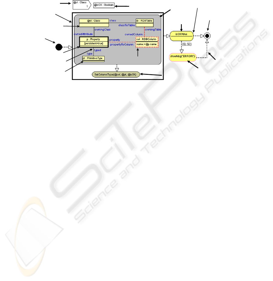
Fig. 1. MOLA procedure example.
In order to iterate through a set of the instances MOLA provides the foreach loop
statement. The foreach loop is executed for each distinct instance that corresponds to
the loop variable and satisfies the constraints of the pattern.
2.1 Template MOLA
The Template MOLA language contains two kinds of statements. Generation
statements are executed during the transformation generation process. Template
statements are meant to be “copied” to the generated “MOLA code” with template
expressions replaced by the appropriate generation time values. Template statements
look similar to ordinary MOLA statements but can be distinguished by graphical style
– the green color.
The most used template statement is template rule. In generation time it is copied
to the generated “code” (i.e., to the relevant generated MOLA procedure). Elements
of the template rule may contain variable textual parts – template expressions
(expressions in angular brackets), to be replaced by the corresponding generation time
values. Similarly to rules the template loop is copied to the generated procedure
during the generation process, including its body. The template loop in its loophead
rule can use all the extensions introduced for template rule. Another important
template construct is Template MOLA procedure call. On the one hand it is used for
description of a generation algorithm, on the other hand it may be reflected in the
generated code.
One of the use cases where Template MOLA could be applied is transformations
for generic metamodels. We may consider one simple transformation of such type –
instance cloning. In order to clone an instance we should create another instance and
paramete
r
foreach
loop
rule (loophead)
start statement
variable
instance creation
loop variable
class element
-
reference
class element
call statement
variable
constraint
text statement
control flow
external call
association link
end statement
45
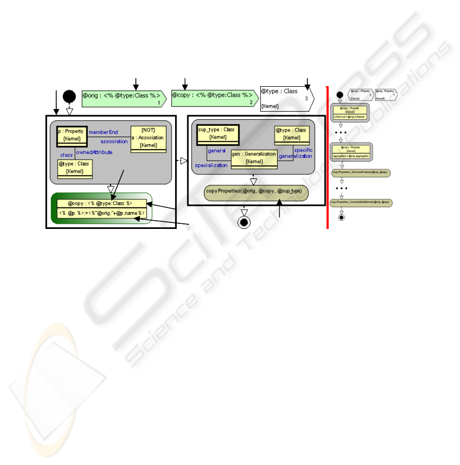
copy values of all attributes. Fig. 2 demonstrates a transformation cloning values of
all attributes of a class in Template MOLA (for details see [3]).
The first generation time loop iterates trough all properties of a class and creates a
rule copying the value of this property. In the template rule template expressions are
used to describe: the type of class element (@type); the property the value is assigned
to (@p); the value of the original attribute. Template expression values will be
determined in generation time and then used in the generated code. The second
generation time loop iterates trough all superclasses of the class and calls the same
MOLA procedure for copying properties of this superclass. In this call the parameter
“@sup_type” is a generation time parameter, while “@orig” and “@copy” are
template parameters. Generation time parameters are used only for transformation
synthesis. Template parameters will appear in generated code. We can run this
Template MOLA on a class and we will obtain a property copier for this particular
class. Structure of the generated procedure can bee seen on the right side of Fig. 2.
Fig. 2. On the left there is a procedure which copies properties values of a class instance. On
the right side there is an example of generated transformation.
2.2 Elements of Dual Nature in Template MOLA
In textual template languages each element belongs either to template part or
generation part. In Template MOLA some elements naturally have a dual role.
The most important structuring element in Template MOLA is template procedure
(also the basic dual role element). It structures the generation algorithm into smaller
parts and at the same time is reused to describe the structure of what should be
generated. It is possible to generate several MOLA procedures from one Template
procedure. The generated code may depend on generation parameter values. We have
to distinguish these procedures and give them different names using the default name
generator or a template expression. When a call statement is processed during the
generation, the name expression of the invoked procedure is evaluated. If the value of
the name expression matches the name of an existing procedure, the existing
procedure will be reused.
Template parameter
Generation loop
Template rule
Template type
Call statement
Generation parameter
Template
expression
46

There can also be cases when we may want to include the code generated by this
procedure into the procedure it is called from (by replacing the call statement). To
solve this problem we allow the “inline” annotation for call statements. It means the
code generated by invoked procedure is embedded in the current one.
Call statements are used both for calling of procedures describing the generation
logic and at the same time reused in generated code. The procedure may contain
template parameters and generation time parameters. The template parameters are
kept in the generated code. Generation time parameters are used only for the
description of code to be generated by the called procedure.
The call statement in Fig 2 has 3 parameters: one generation time (the last) and two
template parameters. In the generated transformation example (the right side of Fig.
2) the generated calls have 2 parameters corresponding to template parameters.
Control flows used for the description of generation algorithm are used also to
decide what kind of control flows are to be included in the generated code. Some
heuristics are used there to infer how control flows should be created. When a new
element is generated in the code a flow from the previous generated element to the
new one is created. The same holds for generation time loops. It means a flow
between the last element generated in the previous iteration and the first element of
next iteration is created (see the right side of Fig. 2 for flows between the rules). This
automatic inference of flows simplifies transformation creation in Template MOLA.
If something more specific is required, merge mechanisms described in section 4
should be used.
3 Why a New Mechanism is Required in Template MOLA
Template based languages (textual or graphical) for program generation from a model
consist of two parts – the generation (model navigation) part and template part. The
template part specifies the object which has to be created. The generation part is based
on control structures for traversing the source model in the order required by the
generation algorithm to be implemented.
An essential property of textual template languages is the fact that an appropriate
loop construct can surround any part of a textual template. This permits to create in a
simple natural way any nested iterative structure in the result. Another feature of
textual languages is that the text is being generated as a single string, with new
elements being added from the current template to one common extension point. If a
reference to the generated part of text is required (such as from variable usage to its
declaration) it is expressed in the concrete syntax using a sort of a name of the
referenced object. These two features determine that in most cases simple control
structures are sufficient for defining the generation algorithm and the transformation
algorithms are basically “single-pass”.
For graphical languages the situation is different. It is not always so easy to enclose
any part of a graphical template in a generation loop. In Template MOLA the main
“regular” cases are supported well from this point of view. These are – a sequence of
rules or loops to be created by a generation loop. A template for such rule or loop then
is contained in the generation loop body (see Fig. 2). The only issue there is the
convention how flows should link the results of iteration steps.
47

However, there may be other “iterative” situations too. The first one is a number of
assignments per class element dependent on some repeating element in the source
model (e.g., see Fig. 3). In Template MOLA it would be quite awkward to define a
generation loop within a template class element.
A similar situation can occur also with edges representing association links in a
rule. There may be a necessity to create a variable number of class elements in a rule
all linked by association links forming a chain or star. It would be natural to assume
that each class element is generated by one iteration of a generation loop. The
corresponding association link must go from class element generated in the current
iteration to a specific element generated in the previous one.
The described situations (and other similar ones) with the necessity to relate
several graphical template elements appearing in adjacent iterations of a generation
loop require some generic and visually easy readable solution. We propose the merge
construct for this purpose. The merge principle should be applicable not only to
generation loops but also to recursive calls in generation time.
4 Merge Mechanisms
Functionally the Template MOLA procedure described in section 2.1 (see Fig. 2.)
performs the required task. However the generated code is a spaghetti code (see the
right side of Fig. 2). More precisely, in a “normal” MOLA all generated attribute
assignments should be placed in the same class element.
To solve this problem we introduce the merge mechanism in Template MOLA. We
introduce this mechanism in a generic way. We introduce the merge name and merge
expression for all template elements. Elements are merged if the value of the merge
expression is equal to the merge name of a previously generated element (of the same
kind). For elements already containing a unique identifier in a container it is possible
to use this identifier in a role of merge name. For Template MOLA it means that
merge name is required for template rule and template loop. For class elements the
class element name is reused in the role of a merge name.
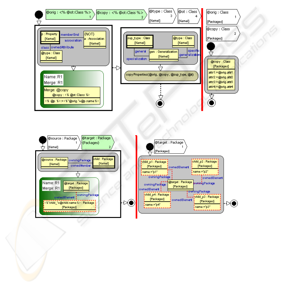
Now we can take a look at the previous example with merge mechanism enabled.
The left side of Fig. 3 demonstrates the transformation from Fig. 2 with merge
annotations. In this case rules created in the first loop are merged, since their merge
names and merge expressions all are equal. Each rule contains one class element and
their merge expressions are equal to the class element name (which is used in the role
of merge name). Therefore the class elements are merged – all attribute assignments
are placed in the same compartment. Consequently, we generate transformation on the
right side of Fig. 3. This is evident in the case when all instances of rule R1 are
generated in the same loop. However, since the template definition contains a
recursive call to the same procedure, it is possible that instances are generated by a
loop in another procedure instance. To ensure that instances generated in all
invocations are merged together, the procedure call should be marked with inline
annotation. It means that all elements generated by this call will be included in this
procedure. Since in the result all elements are included in the same procedure, we can
use merge mechanisms also for them. In this case the rules generated by recursive call
will have the same merge expression. It means we can merge them with the existing
48
rules. Class elements also will be of the same type and with the same name. (Actually
this procedure has one more generation parameter when compared to procedure in
Fig. 2. This parameter is introduced to enable element merge so that they will have
the same type in all recursive calls instead of cast to superclass in recursive calls in
Fig. 2.) It means we can merge also the class elements. As a result all assignments
will be placed in one class element. We should also consider assignment merge, as
there can be inheritance diamonds and in such case one attribute will have multiple
assignments. Assignments are merged by attribute and the first assignment is kept,
others are ignored.
Fig. 3. On the left there is a procedure which copies properties values of a class instance with
merge. On the right side there is example of generated transformation.
Fig. 4. Creation of star shaped rule using merge mechanisms.
There are also other cases when the merge construct is useful. For example, it is
the case when the set of class elements in a rule should vary depending on some
condition. We consider a case when we want to obtain a star-shaped rule of class
elements (see Fig. 4). We merge rules and the center of the star. Using a generation
loop we can create as many peripheral nodes as needed in our star shaped rule.
Similarly to star structure described previously we can also obtain an element chain in
49

a rule. Combining the chain and star mechanisms we can obtain any rule structure
using merge mechanisms. We have to create rules partially because there are no other
ways to add new elements to an existing rule.
The same mechanism demonstrated for rule merge could be reused for obtaining
different control structures between loops and rules. For this purpose it is possible to
repeat an empty rule or loop only with merge name defined.
Rule merge means that class elements and association links to be created in the
new rule will be included in the rule it is merged with, according to the merge
semantics of elements and links. Semantics of loop merge is similar.
Class elements are merged if the merge name of the new class element is equal to
the name of some existing class element in this rule. When merging class elements
their types are also checked. The most important part of class element from the merge
perspective is assignments. New assignments are added to the relevant existing
element. If the element already contains an assignment to this attribute, the new
assignment is ignored. If the merged class element has a condition while the original
one does not, the condition is added. If the original element already has a condition,
then the condition in the merged element is ignored. The same principle is applied to
other features of class element.
For association links it is possible only to add new association links using the
merge mechanism. If there is no link between these two class elements in the rule
then a new link is added. Otherwise the link is ignored. Association link properties are
not merged. Flow merge in a sense is similar to the association link merge. Always
new flows are added. However, it is not checked whether such flow already exists.
5 Related Work
There has been a vast research done on textual template languages but we do not
comment it since our emphasis is on graphical ones.
Another aspect to be taken into account is that the main application of the proposed
Template MOLA is for generation of MOLA transformations from various models
such as mappings between two metamodels. This task is a typical case of Higher-
Order Transformations (HOT). There is significant amount of work on HOT
including the comprehensive survey in [6]. This survey shows that the largest amount
of HOTs has been created for the ATL language [7]. ATL is a textual language and
HOT applications in ATL typically are based on abstract syntax of it with subsequent
ATL generation using TCS [8]. Our experience [3] shows that transformation
definition in abstract syntax for many HOT tasks gets quite complicated and lengthy,
and this was our main motivation for starting research on Template MOLA.
The idea of using a graphical template language for transformation synthesis, to
our knowledge, is new. The comprehensive survey [9] of various features used for
model transformation definition mentions briefly also the template-based approach.
However, the only reference [10] mentioned there applies templates for a very
specific task – how to select prefabricated fragments in the context of product lines.
In fact, the approach closest to ours is the idea of using concrete graphical syntax
for defining graph transformations. The idea was initiated in the ATOM3
environment [11] and continued in [12, 13]. The idea of defining a RHS of a graph
50

transformation rule in a concrete syntax with expressions to be inserted where
required is similar to our template definitions. One significant difference is that the
rule/template application in our approach is controlled by generation statements in
MOLA while in graph transformations there are no explicit control mechanisms. In
addition, in our approach the source model is in abstract syntax (a situation typical for
HOT applications) while the graph transformations are from concrete to concrete
syntax. The ATOM approach to a great deal is based on a simple correspondence
mechanisms between the abstract and concrete syntax and works well in cases where
such a simple correspondence can be defined. On the contrary, our approach is
oriented towards situations where the abstract syntax differs significantly from the
concrete graphical one and this correspondence cannot be defined by simple
mappings (as it is in the case of MOLA or MOF QVT). One more aspect to be
mentioned is the possibility to generate complicated nested structures which is
supported by our merge mechanism proposed in this paper. This feature would be
required, for example, to generate attribute compartment in a UML class symbol and
none of the other approaches seem to offer such a possibility. All the above
mentioned permits to conclude that typical MOLA generation tasks considered in this
paper would be quite difficult to implement in these concrete syntax based graph
transformation approaches.
6 Conclusions
The graphical template based language Template MOLA for MOLA transformation
synthesis is described in this paper. This language leverages the advantage of template
based model to text languages – easy specification of language elements to be
generated – to graphical languages. These are the graphical template statements of
Template MOLA – template rules and template loops, which are transferred to the
new transformation to be generated. Certainly, they can contain variable elements –
template expressions to be replaced in the generation process. The generation process
itself, which depends on the input model, is defined by means of generation
statements – ordinary MOLA statements included in the Template MOLA. These
generation statements are executed in a standard way during the generation process.
A novel feature proposed in this paper is the merge mechanism for templates.
Without merge it would be difficult to define the generation of nested graphical
structures in a simple way. Even generation of large text compartments in graphical
elements (such as attribute compartment in class symbol) requires this mechanism in
general case. But this mechanism has a much wider application – everywhere a
graphical element has to be extended by several steps of the generation process.
Currently Template MOLA is being applied for generation of MOLA
transformations from various other kinds of models, e.g., such as mappings. The
source model typically there is defined in abstract syntax. The template syntax is
defined just for constructs related to MOLA.
However, the approach could be applied to much wider context where generation
of a graphical language from a model is required. Especially, it would be the case
when the generation algorithms are sufficiently complicated. The language for
generation algorithm definition would remain the same MOLA. But the template
51

language would be adapted to the graphical syntax of target language. Our research
shows that a generic definition a template syntax according to “graphical grammar”
(more precisely, presentation metamodel) of the target language would be possible. It
seems plausible that the proposed template mechanisms would be sufficient also for
this case. Certainly, for this to work the relation between the concrete syntax in
templates and the abstract syntax (domain metamodel) used in the generation process
must be defined. Currently in the case of MOLA generation the transformations used
in MOLA editor definition [14] in METAclipse are reused.
One more direction is the possibility to mix the abstract and concrete syntax in
templates and generation rules. This would permit, for example, more possibilities in
generating complicated expressions inside graphical node texts. It should be noted
that ideas of this kind are included also in future plans of [12].
References
1. Eclipse, JET, http://www.eclipse.org/modeling/m2t/?project=jet
2. OMG, MOF Model to Text Transformation Language. v1.0. OMG Document Number:
formal/2008-01-16, 2008
3. Kalnina, E., Kalnins, A., Celms, E., Sostaks, A.: Graphical template language for
transformation synthesis. M. van den Brand, D. Gašević, J. Gray (Eds.): SLE 2009, LNCS
5969, Springer, Heidelberg, 2010, pp. 244-253.
4. Kalnins, A., Barzdins, J., Celms, E.: Model Transformation Language MOLA. Proceedings
of MDAFA 2004, Vol. 3599, Springer LNCS, 2005, pp. 62-76.
5. UL IMCS, MOLA pages, http://mola.mii.lu.lv/.
6. Tisi, M., Jouault, F., Fraternali, P., Ceri, S., Bezivin, J.: On the use of higher-order model
transformations. ECMDA-FA 2009, Vol 5562, LNCS, 2009, pp. 18-33, Springer-Verlag.
7. Jouault, F., Kurtev, I.: Transforming Models with ATL. Satellite events at the MoDELS
2005 Conference, 2006, pp. 128-138.
8. TCS, Textual Concrete Syntax. http://www.eclipse.org/gmt/tcs/
9. Czarnecki, K., Helsen, S.: Feature-based survey of model transformation approaches. IBM
Systems Journal, v.45 n.3, July 2006, pp. 621-645
10. Czarnecki, K., Antkiewicz, M.: Mapping Features to Models: A Template Approach Based
on Superimposed Variants. Proceedings of GPCE’05, Tallinn, Estonia, 2005, pp. 422–437.
11. de Lara, J., Vangheluwe, H.: AToM: A Tool for Multi-formalism and Meta-modelling.
FASE 2002, Vol 2306, LNCS, Springer-Verlag, 2002, pp. 174-188.
12. Baar, T., Whittle, J.: On the Usage of Concrete Syntax in Model Transformation Rules. In
Sixth International Andrei Ershov Memorial Conference, PSI, LNCS, 2006, pp 84-97.
13. Grønmo, R., Møller-Pedersen, B., Olsen, G. K.: Comparison of Three Model
Transformation Languages. ECMDA-FA 2009, Vol 5562, LNCS, Springer-Verlag, 2009,
pp. 2-17.
14. Kalnins, A., Vilitis, O., Celms, E., Kalnina, E., Sostaks, A., Barzdins, J.: Building Tools by
Model Transformations in Eclipse. Proceedings of DSM’07 workshop of OOPSLA 2007,
Montreal, Canada, Jyvaskyla University Printing House, 2007, pp.194–207.
52
