
MAS-ML TOOL
A Modeling Environment for Multi-agent Systems
Enyo José Tavares Gonçalves
Universidade Federal do Ceará, Quixadá, CE, Brazil
Kleinner Farias
Pontifícia Universidade Católica do Rio de Janeiro, Rio de Janeiro, RJ, Brazil
Mariela I. Cortés
Universidade Estadual do Ceará, Fortaleza, CE, Brazil
Allan Ribeiro Feijó
Universidade Estadual do Ceará, Fortaleza, CE, Brazil
Francisco Robson Oliveira
Universidade Estadual do Ceará, Fortaleza, CE, Brazil
Viviane Torres da Silva
Universidade Federal Fluminense, Niterói, RJ, Brazil
Keywords: Multi Agents Systems modelling, MAS-ML 2.0, Graphical Modelling Framework.
Abstract: Multi-Agent Systems (MAS) emerged as a promising approach for developing complex and distributed systems.
However, tools that support development of MASs are essential for this approach is effectively exploited in
industrial context. Therefore, there is a need for tools for the modeling of MAS, because create and manipulate
models without support of an appropriate environment are tedious and error-prone tasks that demands time. This
paper aims to satisfy this need by built a modeling environment domain specific to MAS, implemented as a plug-
in for Eclipse platform. The environment is based on MAS-ML, a modeling language for MAS. This work
focuses the implementation of tool to MAS-ML static diagrams, according version 2.0 of the language.
1 INTRODUCTION
The software industry and academia have researched
and supplied technology in order to attend the demand
of building software systems increasingly complex. In
this scenario, Multi-Agent Systems (MAS) emerged as
promising approach in attempt to better manage this
complexity. According Jennings and Wooldridge
(Jennings and Wooldridge 2000), MAS can be
understood as societies of agents where heterogeneous
and autonomous entities that can work together for
similar or totally different purposes. MAS have become
a powerful paradigm for software engineering (Mubarak
2008) and have been used successfully for the
development of different systems types (Lind 2001)
(Wooldridge and Ciancarini 2001). In this scenario,
MAS modeling languages and tools have a central role
in the development process.
The possibility of a single MAS may encompass
multiple agent types with different internal architectures
(Weiss, 1999) justify the existence of a language to
support the modelling of different internal agent
architectures. In this context, the MAS-ML (Multi-Agent
192
José Tavares Gonçalves E., Farias K., I. Cortés M., Ribeiro Feijó A., Robson Oliveira F. and Torres da Silva V..
MAS-ML TOOL - A Modeling Environment for Multi-agent Systems.
DOI: 10.5220/0003501701920197
In Proceedings of the 13th International Conference on Enterprise Information Systems (ICEIS-2011), pages 192-197
ISBN: 978-989-8425-54-6
Copyright
c
2011 SCITEPRESS (Science and Technology Publications, Lda.)

System Modeling Language) (Silva, Choren and Lucena
2007) was upgraded to comply with this requirement,
resulting in the MAS-ML 2.0 (Gonçalves et al. 2010).
The utilization of CASE tools to support the
software engineering processes is recommended in
order to automate the involved activities. In particular,
modelling tool increases the productivity and can be
useful to ensure the well-construction of the models.
Modelling tools are designed to endure the features and
mechanics related to a specific modelling language.
MAS-ML defines three structural diagrams: class
diagram, role diagram and organization diagram;
and two dynamic diagrams: sequence and activities
(Silva, Choren and Lucena 2007). This work aims
the implementation of a modeling environment to
support the MAS-ML static diagrams on the basis of
the MAS-ML 2.0 metamodel.
This article is organized as follows. Section 2
presents a theory related to MAS-ML language. In
Section 3 the environment is presented, describing
some of its benefits, limitations, mentioning some
issues on implementation. In Section 4 a case study
is presented. In Section 5, the related works are
confronted with these paper contributions. Finally,
Section 6 presents the conclusions and future work.
2 MAS-ML 2.0
MAS-ML 2.0 (Gonçalves et al. 2010) is an
extension of MAS-ML (Silva, Choren and Lucena
2007) modeling language in order to support the
modeling of: (i) simple reflex agents, (ii) Model
based reflex agents and (iii) goal-based agents with
the planning and (iv) utility-based agents.
In practical terms, the aforementioned extension
involved the creation of two meta-classes:
AgentPerceptionFunction, which represents the agent
perceptions and AgentPlanningStrategy, which
represents the planning agent. Both classes are
specializations of the BehavioralFeature meta-class
from UML. Additionally, four stereotypes were created:
formulate-goal-function that represents the formulation
of agent goal; formulate-problem-function that represents
the formulation of the problem; next-function, that
represents the updating of the agent beliefs; and utility-
function that represents the utility degree based on the
current action (Gonçalves et al. 2010).
From the new elements in metamodel, the agent’s
representation in MAS-ML diagrams has increased
four graphical variants, where each one represents each
of the internal architectures mentioned above. In
consistence with the new agent representations, the agent
role representation was associated to three
representations: (i) the original MAS-ML representation,
(ii) a representation without goals, related to model-
based reflex agents, and (iii) a representation without
goals and beliefs, related to simple reflex agents. The
MAS-ML diagrams was modified related the new
features for the modeling the internal agent architectures.
3 MAS-ML TOOL DEVELOPMENT
This section presents the functions, technologies and
details related to the development of the specific
domain modeling environment, MAS-ML tool.
Model driven approach was used, where the
central model and larger abstraction is the self MAS-
ML metamodel. The metamodel represents the
derivation process start point that occurs along a set
of transformations. Five steps realized during the
development are described follow:
Domain Model – first, the MAS-ML metamodel
was specified using the EMOF (Essential Meta-
Object Facility), a metamodel definition language.
The stereotypes were added to ActionClass by
ActionSemantics resource, this semantic present the
options: 0- without stereotype, 1- next-function, 2 –
utility-function, 3- formulate problem-function and
4- formulate-goal-function.
Graphical Definition Model – In this step are
defined the entities and its properties, and relationships.
The metamodel entities and relationships were used.
Tooling Definition Model – In this step are
specified which elements will be exist in tool palette.
This step receives the domain model and definition
model cited previously.
Mapping Model – In this step a mapping between
the domain model, graphical model and tooling model
is building:. The mapping generated was used as input
of the transformation process, which objectify create a
model platform specific. A set of six validating rules
defined using OCL (Object Constraint Language) are
used to check if model was right formed (Table 1).
Table 1: Validation rules description.
Rule Purpose
Rule 1 If agent has plan then it have goal, belief and action.
Rule 2 If agent has plan then it do not have perception.
Rule 3 If agent has a goal, it has a plan or planning
Rule 4 If agent has planning, it has belief, goal, perception
and action.
Rule 5 If agent has plan, it has not planning
Rule 6 If agent has planning, it has not plan
Tooling Generate – The next step, according the
generative approach (Czarnecki and Eisenecker, 2000),
MAS-ML TOOL - A Modeling Environment for Multi-agent Systems
193
is the code generation according to the model created
on last step. The GMF (Graphical Eclipse Framework)
(GMF, 2011) is used, which provide a generative
component and a runtime infrastructure to develop
graphical editors. Follow each diagram development
will be described.
3.1 Class Diagram Development
The MAS-ML tool Class Diagram resultant
available the following elements: 1) Nodes: Class,
AgentClass, OrganizationClass, EnvironmentClass,
ActionClass, PlanClass, Property, Operation, goal,
belief, Perception and Planning; 2) Relationships:
Association, Inhabit, Dependency, Generalization,
Aggregation and Composite 3) Notes.
Moreover, the tool can validate the diagrams
according the generation rules. These rules validate
the internal architectures representation.
3.2 Organization Diagram
Development
Results of class diagram development were used to
create the organization diagram. Additionally, agent
rules and object rules were represented according MAS-
ML 2.0 and the relationships ownership and play, part of
organization diagram, were added. The inhabit
relationship have the semantics changed to allow agents,
agent rules and organization inhabit the environment.
The association, dependency, generalization, aggregation
and composition were removed. These new elements
were in domain model and graphical model, but they
were not used in class diagram (Section 3.1).
3.3 Role Diagram Development
Results of class diagram and organization diagram
development were used to create the role diagram,
since some entities are same in both diagrams. Thus,
the MAS-ML 2.0 metamodel was used too.
Some elements were preserved: Class, Agent Role
and Object Role. Similarly the Association, Control,
Dependency, Generalization and Aggregation
relationships. The graphical representation of elements,
relationships and diagrams of MAS-ML tool are
presented in next section through a case study.
4 CASE STUDY
This section presents a MAS to Moodle using MAS-
ML tool. Initially the Moodle will be described and
after the modelling will be present.
4.1 Moodle
The use of computational tools has a positive impact
on educational activities. Teachers, students and the
system interact through technological resources,
sharing the same workspace and solving problems in
a joint manner, supported by technologies of
distance communication.
Typically, collaborative learning environments
emphasize the Computer-Mediated Communication
(CMC), with tools that enable synchronous (chat
rooms, video conferencing) and asynchronous (e-
mail, whiteboard) communications.
In this context highlight the Virtual Learning
Environment MOODLE (MOODLE, 2011). It is
based on social constructionism and assumes that
people learn best when engaged collaboratively in a
social process of knowledge construction.
4.2 Modelling a MAS to Moodle with
MAS-ML tool
Six agents were proposed to Moodle:
LearningPartnerAgent, SearcherInformationAgent,
PedagogicAgent, UsageHelperAgent, TeamMakerAgent
and CoordinatorAgent. Follow, these agents are
described and each MAS-ML tool model is presented.
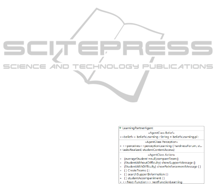
LearningPartnerAgent (Figure 1): Modeled as a
model based reflex agent. This agent selects messages
of support and reinforcement for students to display
based on the difficulties and successes he has in the
discussions and / or the proposed tasks and / or content.
Figure 1: Learning Partner Agent created in MAS-ML
tool.
PedagogicAgent (Figure 2): It is a goal-based
agent with planning. Its function is to help the
student through messages related to the theme on
which he is involved in different courses and
disciplines that participate. It also suggested courses
and subjects that are related to the student interests.
ICEIS 2011 - 13th International Conference on Enterprise Information Systems
194
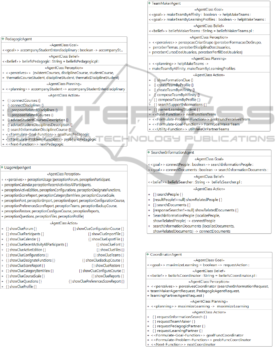
UsageHelperAgent (Figure 3): Modeled as a
simple reflex agent. It is responsible for providing
tips on how to make better use of specific tools.
TeamMakerAgent (Figure 4): Modeled as a
utility based agent, its function is to form or join
groups according to the proposed subject or learning
profile suggested by the trainer.
Figure 2: Pedagogic Agent created in MAS-ML tool.
Figure 3: Usage Helper Agent created in MAS-ML tool.
SearcherInformationAgent (Figure 5): Agent-
based goal with plan. This agent is responsible for
locating people within Moodle environment are
involved in related disciplines and groups the same
topic of the student. Additionally, this agent search
for documents (pages, projects and other digital
objects) that related with the topic of interest.
CoordinatorAgent (Figure 6): Modeled as a
goal-based agent with planning, this agent should be
responsible for ordering the actions of other agents,
thus mediating the same conversation.
Figure 4: Team Maker Agent created in MAS-ML tool.
Figure 5: Searcher Information Agent created in MAS-ML tool.
Figure 6: Coordinator Agent created in MAS-ML tool.
MAS-ML TOOL - A Modeling Environment for Multi-agent Systems
195
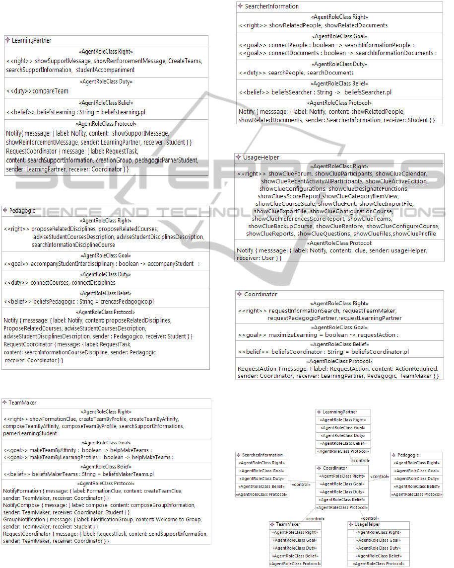
Six agent roles associated to an agent showed were
proposed to Moodle: LearningPartner (Figure 7),
Pedagogic (Figure 8), TeamMaker (Figure 9),
SearcherInformation (Figure 10), UsageHelper (Figure
11) and Coordinator (Figure 12). Follow, the agent role
model in MAS-ML tool is presented.
Figure 7: Learning Partner Role created in MAS-ML tool.
Figure 8: Pedagogic Role created in MAS-ML tool.
Figure 9: Team Maker Role created in MAS-ML tool.
Finally, Figure 13 depicts the Role Diagram for
Moodle MAS and Figure 14 depicts the
Organization Diagram for Moodle MAS.
Figure 10: Searcher Information Role created in MAS-ML tool.
Figure 11: Usage Helper Role created in MAS-ML tool.
Figure 12: Coordinator Role created in MAS-ML tool.
Figure 13: Role Diagram created in MAS-ML tool.
ICEIS 2011 - 13th International Conference on Enterprise Information Systems
196

Figure 14: Organization Diagram created in MAS-ML
tool.
5 RELATED WORKS
Whereas a broad scope in relation to support tools for
the modeling of SMAs (AgentTool 2011) (Padgham,
Winikoff Thangarajah and 2008). However, a key issue
is that the tools are projected to support the diagram
construction in an specific modeling language. Thus,
the advantages and limitations of these languages are
propagated to the tools that implement them.
Considering the already existent modeling tools
related to MAS-ML, VisualAgent (De Maria et al.
2005) is a software development environment that
aims to assist developers in the specification, design
and implementation of MASs.
VisualAgent is based on the original MAS-ML
metamodel. Consequently, the support to the modeling
for agents with different internal architectures can be
limited. VisualAgent neither model checking
mechanism is provided. The absence of this feature in
VisualAgent can compromise the quality of models
and generated code. Moreover, the lack of
documentation and source code access hinders their
project continuity.
6 CONCLUSIONS
This paper presents a tool that represents a concept
proof of modeling language MAS-ML, focused on
static diagrams. In their current version, MAS-ML 2.0
incorporates features to model rational agents in an
appropriate manner, providing a better level of
abstraction to represent the internal characteristics of
SMAs. With the environment is possible, support the
modeling activity, check the correctness of the models
construction and hold their persistence. In the context
of the model oriented development, the diagrams can
be used in the transformation process to code
generation in specific agent platforms.
As future work, some improvements can be made
on the graphical representation of builders to represent
with more faithfulness the proposed representation in
the MAS-ML metamodel. Additionally, support for
modeling of dynamic diagrams of the MAS-ML 2.0.
ACKNOWLEDGEMENTS
The authors are grateful to F. R. Oliveira and F. J. Maia
for useful comments and suggestions. A. Feijó
acknowledges CNPq/Brazil for financial support.
REFERENCES
agentTool (2011), Available in http://agenttool.cis.ksu.edu/,
Accessed in 10 January of 2011.
Czarnecki, K.; Eisenecker, U. (2000). Generative
Programming - Methods, Tools, and Applications,
Adison-Wesley, June 2000.
De Maria, B. A.; Silva, V. T.; Lucena, C. J. P.; Choren, R.
(2005). VisualAgent: A Software Development
Environment for Multi-Agent Systems. Proceedings of
the 19 Brazilian Symposium of Software Engineering,
Tool Track, Brazil.
GMF (2011). Available in www.eclipse.org/modeling/gmf/,
Accessed 10 January of 2011.
Gonçalves, E. J. T.; Cortés, M. I.; Campos, G. L.; Silva, V. T.
(2010). Extending MAS-ML to Model Proactive and
Reactive Software Agents. 12th International Conference
on Enterprise Information System, Portugal.
Jennings, N.; Wooldridge, M. (2000), Agent-Oriented
Software Engineering, In Bradshaw, J. (Ed.)
Handbook of Agent Technology, AAAI/MIT Press.
Lind, J. (2001), Issues, In: Ciancarini P. e Wooldride M.,
Agent-Oriented Software Engineering, LNCS 1957,
Germany, Springer, p.45-58.
MOODLE. Course Management System. Available in:
http://moodle.org/. Accessed in January 10, 2011.
Mubarak, H. (2008), Developing Flexible Software Using
Agent-Oriented Software Engineering, IEEE Software,
Sep/Oct, IEEE Computer Society, pp. 12-15.
Padgham, L.; Thangarajah, J.; Winikoff, M. (2008)
Prometheus Design Tool, in 23th AAAI Conference on
Artificial Intelligence, Chicago, EUA, pp.1882-1883.
Silva, V. T.; Choren, R.; Lucena, C. J. P. de (2007). MAS-
ML: A Multi-Agent System Modeling Language. In:
Conference on Object-oriented programming, systems,
languages, and applications, 18th annual ACM
SIGPLAN; CA, USA, ACM Press, pp. 304-305.
Wooldridge, M.; Ciancarini, P. (2001), Agent-Oriented Software
Engineering: the State of the Art, In Agent-Oriented
Software Engineering, LNCS1957, Springer, p. 1-28.
MAS-ML TOOL - A Modeling Environment for Multi-agent Systems
197
