
A 0.45NW, 0.5V, 59-DB DR, G
M
-C LOW-PASS FILTER
FOR PORTABLE ECG RECORDING
Chutham Sawigun, Senad Hiseni and Wouter A. Serdijn
Biomedical Electronics Group, Electronics Laboratory, Delft University of Technology,
Mekelweg 4, 2628 CD, Delft, The Netherlands
Keywords: Analog Circuit, G
m
-C Filter, Low-Pass Filter, Sub-Threshold CMOS, Ultra Low-Power, Weak Inversion.
Abstract: This paper presents the design of a sub-threshold CMOS G
m
-C low-pass filter in a portable ECG detection
system. The proposed filter is formed by cascading 6 stages of identical 1
st
-order low-pass sections. With a
minimum number of active components in the 1
st
-order section, the noise contribution of the circuit can be
kept low while minimizing the size of transistors and capacitors. The filter cut-off frequency is designed to
be adjustable over the range from 100Hz to 250Hz by changing the bias current. Circuit simulations, using
AMS’ 0.18µm CMOS technology and operating from a 0.5V supply voltage, show that, for a cut-off
frequency of 150Hz, the filter draws 0.9nA of current. An input referred noise of 88µV
rms
is obtained while
for 1% total harmonic distortion, the voltage swing can be as high as 0.23Vpp.
1 INTRODUCTION
As a consequence of the heart activity,
electrocardiograms (ECGs) can be recorded by skin
electrodes (Webster, 1995). By measuring the ECG
signal, the heart condition can be diagnosed and
monitored. In a portable ECG detection system a
low-pass filter (LPF) is required to impede high
frequency electrical signals from non-cardiac
muscles (muscle noise or artifact) (Garcia-Niebla
and Serra-Autonell, 2009) and to avoid aliasing in
the sampling process of an analog to digital
converter (ADC) (Lee and Cheng, 2009).
In order to minimize power consumption of the
LPF in the portable ECG detector, weak inversion
operation of CMOS devices is the first condition to
handle for a design using very little bias current.
Nonlinearity, noise and mismatch of this operating
region are, however, more severe than that of its
strong inversion counterpart. Recently, the
systematic design of an ECG filter optimizing those
non-idealities within a linearized G
m
-C filter
structure has been reported (Lee and Cheng, 2009).
A very good figure-of-merit (FoM) was obtained at
a power consumption of only 453nW.
To further reduce the power consumption, this
paper proposes a LPF design technique that does not
require a linear G
m
. Instead of trying to linearize the
G
m
cell to obtain a good performance before
substituting it into a passive prototype LC filter, a
nonlinear G
m
with feedback is used to create a 1
st
-
order LPF cell before forming the higher order filter
by cascading the identical 1
st
-order cells. This
approach can reduce a lot of power while other
performances remain the same (or become even
better) in the pass-band of the LPF. To demonstrate
this idea, we exploit a follower integrator (FI)
(Mead, 1989) as the fundamental element of our
ECG filter, which subsequently is realized by
cascading 6 FI stages. Simulation results, using
Cadence with AMS’ 0.18µm CMOS model
parameters, confirm that for comparable
performance, the proposed ECG filter’s power
consumption is three orders of magnitude lower than
that of the LPF in (Lee and Cheng, 2009).
The remaining sections of the paper are
organized as follows. In Sec. II, a brief description
of the ECG portable detector is shown. The basic
concept of the 1
st
-order FI based filter is described
and a 6
th
-order Bessel LPF is presented in Sec. III.
Next, Sec. IV presents the simulation results. The
conclusions will be drawn in the last section.
2 LOW-PASS FILTER DESIGN
ISSUES IN ECG DETECTOR
Fig. 1 illustrates a portable ECG detection device.
324
Sawigun C., Hiseni S. and A. Serdijn W..
A 0.45NW, 0.5V, 59-DB DR, GM-C LOW-PASS FILTER FOR PORTABLE ECG RECORDING.
DOI: 10.5220/0003764103240328
In Proceedings of the International Conference on Biomedical Electronics and Devices (BIODEVICES-2012), pages 324-328
ISBN: 978-989-8425-91-1
Copyright
c
2012 SCITEPRESS (Science and Technology Publications, Lda.)
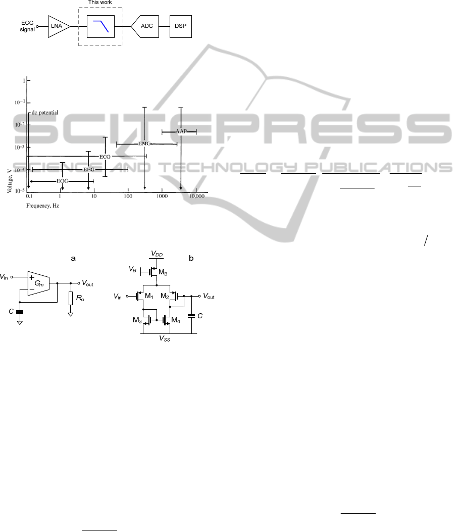
First, a low noise amplifier is used to amplify the
very weak ECG signal. Depending on the electrodes
used, ECG signal amplitudes can range from around
50µV to approximately 4 mV (see Fig. 2) (Webster,
1995). Next, high frequency components of the ECG
signal are filtered out to decrease the out-of-band
noise. Herein, the recommended low-pass cut off
Figure 1: Portable ECG detection.
Figure 2: Different biopotential voltages versus frequency
spectrum (Webster, 1995).
Figure 3: Follower integrator a) macro-model b) transistor
level circuit.
frequencies are 150Hz and 250Hz in case of adults
and children, respectively (Kligfield et al., 2007)
(Rijnbeek et al., 2001). Afterwards, an ADC is
utilized in which the analog input signal is quantized
and converted into digital values as needed for the
subsequent digital signal processing (DSP).
Since there is a large variation on the expected
amplitude of the input signal, the amplifier and filter
are required to have a minimal Dynamic Range
(DR), according to (Lee and Cheng, 2009) (Luo and
Johnston, 2010), of
max
min
2
20log 44dB
ECG
DR
ECG
⎛⎞
=≅
⎜⎟
⎝⎠
.
(1)
To avoid aliasing, the filter should provide sufficient
attenuation in the stop-band. In (Lee and Cheng,
2009), for a sampling frequency (f
s
) of 1kS/s, 29dB
attenuation at 500Hz (f
s
/2) was found. In this work,
we target the same numbers of attenuation and
sampling rate. Besides, to minimize phase distortion,
a constant group delay over the pass-band response
of the filter should be obtained (Hejjel and Kellenyi,
2005).
3 FOLLOWER INTEGRATOR
BASED LOW-PASS FILTER
The FI is conceptually shown in Fig. 3a. It
comprises a transconductor and a grounded
capacitor connected in a negative-feedback fashion.
Resistor R
o
represents the output resistance of the
transconductor to ground (which is usually many
times larger than
1
m
G
−
). We then find that
out
in
()
11
() 1
1
1
1
mo
mo
o
m
mo
Vs GR
C
Vs GR
sCR
s
G
GR
⎛⎞
=≅
⎜⎟
+
⎛⎞
⎝⎠
+
+
⎜⎟
+
⎝⎠
.
(2)
As one can see from (2), the FI provides a low-pass
frequency response with a pass-band gain and cut-
off frequency of
K ≅ 1 and f
c
= 2
m
GC
π
,
repectively.
According to this characteristic,
V
out
is following
V
in
closely for input signal frequencies below f
c
. In
other words, the differential input voltage of the
G
m
is kept small, which helps the filter to suffer less
from nonlinearity of the
G
m
itself. Benefitting from
the fact mentioned above, high dynamic range low-
pass filters realized from nonlinearized
G
m
s have
been successfully implemented in (Python, 1999)
and (D’Amico et al., 2006). Hence, without
linearization, the
G
m
s can be made compact and low
noise and low-power consumption can be expected
while a good linearity can be achieved due to the
large loop-gain at low frequencies.
The FI can be simply formed by the circuit
shown in Fig. 3b (Mead, 1989). It comprises a
simple differential pair M1-M2 biased by current
source MB with a current mirror active load, M3-
M4, and a grounded capacitor,
C.
Neglecting channel length modulation, the
capacitance current can be found to be
in out
tanh
2
CB
T
VV
II
nU
⎛⎞
−
=
⎜⎟
⎝⎠
.
(3)
The nonlinear relation in (3) is shown here to give
A 0.45NW, 0.5V, 59-DB DR, GM-C LOW-PASS FILTER FOR PORTABLE ECG RECORDING
325
an intuitive understanding that at low frequencies I
C
≅ 0 and consequently, V
in
and V
out
are forced to be
equal. The hyperbolic tangent function will not
produce any distortion in this case. But for higher
frequencies, the phase difference between
V
in
≅ V
out
becomes greater and more distortion will be
produced.
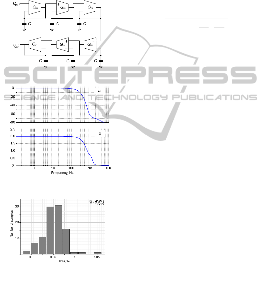
Figure 4: FI based 6
th
order LPF.
Magnitude, dBGroup delay, ms
Figure 5: Frequency response of the proposed filter
a) magnitude response b) group delay.
Figure 6: Monte-Carlo simulation.
The power spectral density of the output noise
voltage can be found to be (at low frequencies)
13
2
811
()
F
vno
mOX
K
nkT
Sf
GCfWLWL
⎛⎞
=+ +
⎜⎟
⎝⎠
,
(4)
where
K
F
is a flicker noise parameter, all the other
symbols have their usual meanings,
12
WL WL
=
,
34
WL WL
=
and G
m
=I
B
/2nU
T
.
For our application that deals with input
frequencies below a few hundred hertz, the majority
of the noise power is not only contributed by the
thermal noise but also by 1/
f noise. From (4) the
noise corner frequency can be found as
()
corner
2
13
11
8
BF
OX
qI K
f
nkT C
WL WL
=
⎛⎞
+
⎜⎟
⎝⎠
.
(5)
We can see from (5) that to keep
f
corner
low, the
FI requires large transistor sizes and low bias
current.
The requirements of the filter mentioned in
Section II can be simply met by cascading 6
identical FI stages as shown in Fig. 4. Formed by
identical circuit elements this structure provides a
Bessel transfer function. All the
G
m
s are realized by
the transconductor in Fig. 3b. The advantages of this
filter topology are pointed out in the following list:
• As a consequence of the use of identical
components in a modular structure, the
filter’s sensitivity to capacitance and
transconductance variations is low.
• The linearity of the filter is less susceptible
to mismatch due to the unity gain feedback
in each 1
st
-order section.
• The internal node voltage swings are all
identical in the pass-band. Hence, the filter
distortionless output swing is maximized
(Groenewold, 1992).
• The contributions of all
G
m
stages to the
overall output noise are almost equal.
Hence, the filter output noise is minimized
(Groenewold, 1992).
• Constant group delay can be expected in
the pass-band frequency range.
The drawback is that the transition band roll-off
is less steep compared to other filter types.
For a cutoff frequency of 150Hz, realizing this
filter circuit within an acceptable chip area and
obtaining very low power consumption to achieve a
pass-band gain of 0dB and sufficient magnitude
attenuation at
f
s
/2 = 500Hz are feasible.
4 CIRCUIT SIMULATIONS
The LPF circuit has been designed to be
BIODEVICES 2012 - International Conference on Biomedical Electronics and Devices
326

implemented in AMS’ 0.18
μm CMOS process
technology. The bias current of each FI circuit is set
to
I
B
= 0.15nA. The total bias current for the filter
core equals 0.9nA. Operated from a 0.5V supply,
this results in 0.45nW static power. Dimensions of
the MOS transistors used are listed in Table. I. The
transistors are largely sized to reduce the transistor’s
flicker noise and mismatch. The total capacitance
equals 6pF (1pF per stage).
Table 1: Transistor Dimensions.
MOSFET W [µm] L [µm]
M
1
, M
2
:M
3
, M
4
: M
B
15:8:12 2.5:8:6
Table 2: Performance Summary and Comparison.
Lee and Cheng,
2009
(Measurement)
This work
(Simulation)
Approx. type Butterworth Bessel
CMOS Tech. 0.18µm 0.18µm
V
D
D
1V 0.5V
P 453nW 0.45nW
order, N 5 6
Total cap. 5.76pF 6pF
Pass-band gain –10.5dB 0dB
f
–3dB
250Hz 150Hz
f
s
/2 attenuation –29dB* –28dB
IRN 340µV
rms
88µV
rms
DR@THD
(50Hz f
i
n
)
40.3dB@-48.6dB
59.3dB@-40dB,
52.1dB@-48.4dB
FoM 8.99×10
-12
J
8.43×10
-15
J,
9.6×10
-15
J
* From the simulated frequency response
Fig. 5 shows the simulated magnitude response
and the group delay of the proposed filter. The
f
–3dB
cut-off frequency is found at 150Hz and a magnitude
attenuation of –28dB is obtained at 500Hz. The
group delay of 2ms remains constant over the range
of DC to 100Hz. At 250Hz a 0.6ms delay deviation
from 2ms is found.
For a more realistic estimation of the circuit
linearity, we also performed a statistical analysis.
The effect of transistor mismatch is verified through
a Monte-Carlo simulation for the condition of a
0.11V input amplitude. For 100 runs, the obtained
result is very satisfying as can be seen from the
histogram in Fig. 6. The mean value of the THD
obtained is 0.95% with a standard deviation of
0.024%.
Table II shows a performance comparison
between the proposed LPF and the measured results
from the recently reported ECG LPF (Lee and
Cheng, 2009) that relies on a linearized
G
m
composed of several transistors and a filter structure
that does not contain local unity-gain feedback
loops. Hence, high amounts of noise and mismatch
induced nonlinearity cannot be avoided. Due to the
compact
G
m
circuit and the local negative feedback
in the FI structure, our proposed filter outperforms
the previous ECG filter on most of its performance
except the transition band attenuation and the value
of the capacitance while the power consumption of
our design is 1000 times lower. Considering the
FoM (Vittoz and Tsividis, 2002) defined by
()
1
3dB
PNf DR
−
−
×× ×
, where, N is the filter order and
P is the power consumption, the proposed LPF also
improves the FoM by approximately three orders of
magnitude.
5 CONCLUSIONS
The design of a 6
th
-order G
m
-C low-pass filter using
nonlinear CMOS transconductors operating in their
sub-threshold region has been presented. The
presented filter features good linearity in the pass-
band and mismatch insensitivity due to its embedded
negative feedback within each fundamental FI cell.
Low noise and low-power consumption are achieved
from the compactness of the ordinary
transconductors that we employ. The obtained
simulation results confirm that our design fits
portable ECG detection requirements well.
REFERENCES
D’Amico S., Conta M., Baschirotto A. 2006. A 4.1mW
10MHz fourth-order source-follower-based conti-
nuous-time filter with 79-dB DR, IEEE J. Solid-State
Circuits, pp. 2713-2719.
Garcia-Niebla J., Serra-Autonell G., 2009. Effects of
inadequate low-pass filter application, Journal of
Electrocardiography, vol. 42, pp. 303-304.
Groenewold G., 1992, Optimal dynamic range integrators,
IEEE Trans. Circuits Syst. I, vol. 39, p.614 .
Hejjel L., Kellenyi L., 2005. The corner frequencies of the
ECG amplifier for heart rate variability analysis,
Physiological Measurement, vol. 26, pp. 39–47.
Kligfield P., Gettes L. S., Bailey J. J., et al., 2007.
Recommendations for the standardization and
interpretation of the electrocardiogram, J. Am. Coll
Cardiol, vol. 49, no. 10, pp 1109–1127.
Lee S. Y., Cheng C. J., 2009. Systematic design and
modeling of a OTA-C filter for portable ECG
detection, IEEE Trans. Biomed. Circuits Syst., vol. 3,
no. 1, pp. 53-64.
Luo S., Johnston P., 2010. A review of electrocardiogram
filtering, Journal of Electrocardiology, vol. 43, no 6,
pp 486 – 496.
A 0.45NW, 0.5V, 59-DB DR, GM-C LOW-PASS FILTER FOR PORTABLE ECG RECORDING
327

Mead C. A., 1989 Analog VLSI and Neural Systems.
Addison-Wesley Publishing Co., Reading, MA, 1989.
Python D., Porret A. S., Enz C., 1999. A 1V 5
th
-order
Bessel filter dedicated to digital standard proceses,
Proc. IEEE CICC, pp. 505-508.
Rijnbeek P. R., Kors J. A., 2001. Witsenburg M.,
Minimum bandwidth requirements for recording of
pediatric electrocardiograms, Circulation, vol. 104, pp
3087-3090.
Vittoz E., Tsividis Y., 2002 Frequency-dynamic range-
power, in Trade-Offs in Analog Circuit Design, C.
Toumazou, G. S. Moschytz, and B. Gilbert, Eds.
Boston, MA: Kluwer, ch. 10.
Webster, J. G., 1995. Medical Instrumentations:
Application and Design, New York: Wiley.
BIODEVICES 2012 - International Conference on Biomedical Electronics and Devices
328
