
Fuzzy Control of a Hybrid Renewable Power System based
on Real-time Matlab-PLC Communication through OPC
Isaías González Pérez, A. José Calderón Godoy and Manuel Calderón Godoy
Industrial Engineering School, University of Extremadura, Avenida de Elvas, Badajoz, Spain
Keywords: Hybrid Power System, Renewable Energy, Electrolyzer, Fuzzy Control, OPC, PLC.
Abstract: This paper presents the design of a fuzzy logic controller to operate an electrolyzer of an experimental test-
bed of hybrid wind-solar system with hydrogen storage. This controller runs in Simulink and is linked
through Open Process Control interface with the industrial programmable logic controller responsible of
global management of the installation. Real-time data exchange and control of the process variables have
been successfully achieved and obtained results under real conditions are presented.
1 INTRODUCTION
Hybrid power systems (HPS) refer to all systems
that combine different energy technologies (RES,
hydrogen, biomass etc.) in order to meet the required
electrical and thermal loads of the consumer
(Zervas, 2008). A wind-solar test-bed with hydrogen
support has been developed and installed in the
Industrial Engineering School of the University of
Extremadura in Badajoz. It is a laboratory scale
system for testing the integration and control of a
stand-alone hybrid installation. Its components are
two PV modules, a wind-turbine generator, a lead-
acid gel battery, a PEM (Proton Exchange
Membrane) electrolyzer, a PEM fuel cell, a metal-
hydride system for hydrogen storage, and a
supervisory control and data acquisition system.
This system is based on a Siemens S7-313C-2DP
Programmable Logic Controller (PLC) which
integrates various modules for connecting sensors.
The electrolyzer is used for hydrogen production
from deionized water and electricity provided by the
PV modules. The hydrogen is stored in a set of metal
hydride bottles until feeding the fuel cell to provide
electricity according to the management strategy.
Figure 1 shows the wind-solar generator installed on
the flat roof of the School and the rest of the
elements in the laboratory.
One of the main problems of the HPS is related
to the control and supervision of the energy
distribution. There are power fluctuations because of
the variability of the renewable energy, which cause
disturbances that can affect the quality of the power
delivered to the load. The role of the controller is to
control the interactions of the various system
components and the energy flow within the system
to provide a stable and reliable source of energy.
Figure 1: Wind-solar generator, electrolyzer and
laboratory test-bed.
Literature review reveals that over the last
decades, hybrid systems have grown rapidly and
their technology has proven its competitiveness for
remote area applications. It is observed that
approximately 90% of studies reported are on
design/economic aspects of hybrid systems (Nema,
2009). Research studies about control are, hence,
scarce but there is an increasing interest on control
strategies and systems for hybrid installations.
Different control techniques have been studied for
HPS such as control based on the battery state of
charge (Ipsakis, 2009; Uzunoglu, 2009), logical
15
González Pérez I., José Calderón Godoy A. and Calderón Godoy M..
Fuzzy Control of a Hybrid Renewable Power System based on Real-time Matlab-PLC Communication through OPC.
DOI: 10.5220/0003992300150021
In Proceedings of the 9th International Conference on Informatics in Control, Automation and Robotics (ICINCO-2012), pages 15-21
ISBN: 978-989-8565-21-1
Copyright
c
2012 SCITEPRESS (Science and Technology Publications, Lda.)

control (El-Shatter, 2006; Khan, 2009), sliding mode
control (Battista, 2006; Valenciaga, 2005), fuzzy
control (Bilodeau, 2006; Erdinc, 2011; Erdinc, 2012;
Hajizadeh, 2007; Jeong, 2005; Kyriakarakos, 2012;
Stewart, 2009), optimal control based on genetic
algorithms (Dufo, 2007), predictive control (Wu,
2009; Zervas, 2008), and Petri nets (Calderón, 2010;
Figueiredo, 2008; Lu, 2010).
Lately, Fuzzy Logic Control (FLC) has received
growing attention from researchers. Jeong et al.
(Jeong, 2005) designed and tested a fuzzy controller
for the load management of a fuel cell-battery hybrid
system. El-Shatter (El-Shatter, 2007) applied fuzzy
logic to control the duty cycle of two buck boost
converters of the wind generator into a hybrid wind-
PV-fuel cell system. In (Erdinc, 2011) Erdinc and
Uzunoglu developed and simulated with real
meteorological data a fuzzy controller to manage a
hybrid system consisting of wind-PV generators,
fuel cell, electrolyzer and battery. In (Erdinc, 2012)
Erdinc et al. tested a fuzzy controller in real wind-
PV-battery-fuel cell system for determining the fuel
cell power reference. Hajizadeh and Aliak
(Hajizadeh, 2007) simulated a fuzzy controller as
second control layer for a hybrid fuel cell-battery
system to decide the operating point of the fuel cell.
Bilodeau and Agbossou (Bilodeau, 2006) developed
and simulated a fuzzy logic controller defined using
the Fuzzy Logic Toolbox of Matlab for determining
the power set points of the fuel cell and the
electrolyzer in a stand-alone wind-solar hybrid
system. Stewart et al. (Stewart, 2009) simulated
fuzzy control applied to control the switches of the
battery, the fuel cell and the grid connection of a
hybrid PV-battery-fuel cell system for a residential
installation. Kyriakarakos et al. (Kyriakarakos,
2012) designed and simulated a fuzzy controller
developed using the Fuzzy Logic Toolbox of Matlab
for energy management of a wind-PV-fuel cell-
electrolyzer-battery power system including a
desalination unit.
Furthermore, several authors have reported
successful applications of OPC communication
between Matlab and Simulink environment and a
PLC of S7 series from Siemens (Lieping, 2007;
Linlin, 2011; Manuj, 2011; Mingliang, 2011).
The authors propose a control scheme based on a
six input and one output fuzzy logic controller. It has
been designed and tested for driving the electrolyzer
of the aforementioned renewable energy system.
This controller runs in Simulink and the control data
exchange with the PLC responsible of global
management is carried out in real time through OPC
technology. The rest of the paper is organized as
follows. Section 2 describes the control system, the
FLC features and the integration architecture for
real-time control by means of the PLC. In section 3
the results corresponding to the hybrid test-bed
under real conditions are shown. Finally,
conclusions and further works are outlined.
2 CONTROL SYSTEM
The test-bed monitoring and control system is
implemented by the PLC S7-313C-2DP. It has
electronic modules, Siemens SM331 and SM334
models, for connecting analogue sensors with
voltage and current outputs. Data are displayed and
stored on a TP277B touch panel (Siemens) running a
SCADA (Supervisory Control and Data Acquisition)
application. The touch panel logs the variables of
interest at one minute intervals from the PLC's
memory by a permanent MPI (Multi-Point Interface)
connection.
WinCC flexible is a Human-Machine Interface
(HMI) software. It can solve tasks like visualization,
acquisition and data storage and control of
automated processes. WinCC flexible RunTime is a
HMI based on PC and OPC communication is one of
its functionalities.
MATLAB is a kind of math analysis tool
developed by MathWorks CO, which integrates
OPC Toolbox to facilitate interoperability with other
software which is used as an OPC server.
The fuzzy logic controller has been implemented
with the Fuzzy Logic Toolbox of Simulink/Matlab
environment, which communicates with the
management PLC via OPC technology.
2.1 OPC
Open Process Control (OPC), also known as OLE
for Process Control, is a series of seven
specifications defined by the OPC Foundation for
supporting open connectivity in industrial
automation. OPC uses Microsoft® DCOM
technology to provide a communication link
between servers and clients. It has been designed to
provide reliable communication of information in
process plants, such as petrochemical refineries,
automobile assembly lines, and so on.
The specification of OPC technology contains
Server and Client, using the Client/Server mode.
Server is the supplier of data and Client is the user of
data. They establish a complete set of rules between
hardware supplier and software developer. An OPC
client is able to connect to one or more OPC Servers,
ICINCO2012-9thInternationalConferenceonInformaticsinControl,AutomationandRobotics
16

and several OPC clients are also allowed to
simultaneously connect to the same OPC Server.
A WinCC flexible RunTime software application
has been developed. It runs in the computer
connected to the PLC via Ethernet by using the
communications processor CP-343 Advanced. This
application accesses to data blocks in the PLC
memory where both sensors measurements
(electrolyzer current, pressure, etc.) and calculated
values are stored (battery state of charge, averaged
irradiance, etc.). So, these values are available for
the OPC client. In this case, the OPC Toolbox of
Matlab allows the communication with Simulink
acting as OPC client. Figure 2 shows the
communication structure between the PLC,
Simulink and WinCC.
Figure 2: Diagram of communication structure between
Simulink, WinCC and the PLC.
2.2 Fuzzy Logic Controller
The main advantages of fuzzy logic are the fast
decision capability and that there is no need of
historical data neither mathematical models. Erdinc
and Uzunoglu (Erdinc, 2011) indicate the usefulness
of these features and the suitable structure of fuzzy
logic for the control of power systems.
The control objective of the proposed strategy is
to regulate the operation point of the PEM
electrolyzer depending on the conditions of the
system such as energy availability from PV
generator, from the battery, and others. A dc-dc
converter carries out the conditioning of voltage and
current provided by the PV modules to the
electrolyzer levels. The PLC applies a signal control
to this converter by means of an analogue output of
voltage. This voltage level is generated from the
FLC output.
FLC input variables are: State Of Charge (SOC)
of the battery, solar irradiance, temperature of PV
panel, compromise current, pressure of metal hydride
system, difference between compromise and
electrolyzer currents. This latter is considered as error
signal because it represents the deviation between the
surplus available current and the one delivered to
electrolyzer. This error signal is calculated in
Simulink before entering the FLC block.
Compromise current is defined by the authors as
the possible surplus current that would be produced
in the installation if the PV generator was providing
the maximum possible current. It plays the role of
threshold to decide if the energy surplus is enough
for the electrolyzer operation. It is calculated as the
difference between the maximum current from
modules, Ipmax, and the load current. Ipmax
depends on the panels voltage, Vpan, and the
irradiance, G, according to equation 1 that has been
obtained from experimental data:
Ipmax = 2 * G * (0.0049 – 0.0002 * Vpan) (1)
The battery SOC is estimated in the PLC with
the Ampere-counting method (Piller, 2001) from
values of current and capacity of the battery.
Incident irradiance in the PV modules plane is
used. It is averaged each 5 minutes in order to
reduce the transitory fluctuations due to clouds.
The PV panel temperature is measured with a Pt-
100 probe on the backsurface. This variable is
included in control process because the generation
capacity and the performance of the modules depend
on their temperature. The lower temperature is, the
higher performance will be.
Once the battery is charged enough and the load
demand is being satisfied, the PV modules provide a
surplus current used for hydrogen generation. These
conditions are evaluated by means of the incident
irradiance, the compromise current and the battery
SOC. Furthermore, technological factors must be
taken into account such as the no operation of the
fuel cell and the available capacity for storing in the
metal hydride bottles, i.e., their pressure has to be
under the maximum level.
When such conditions are fulfilled, the voltage
control signal generated by the FLC is applied to the
dc-dc converter that feeds the electrolyzer from PV
modules. This voltage varies with meteorological
and technological changes according to the rules
defined for the controller, so that the current drawn
by the electrolyzer and, hence, the flow of hydrogen
produced are adapted to the availability of energy.
The structure of the FLC has been made as
simple as possible. The fuzzy controller is of
Mamdani type, the And method is Min, the
implication operator is Min, the Aggregation is Max
and the defuzzification strategy is the Centroid of
area. The membership functions have been defined
based on the experience acquired by the research
team through the operation of the test-bed
(Calderón, 2010; Calderón, 2011). Triangular,
trapezoidal, S-shaped and Z-shaped membership
FuzzyControlofaHybridRenewablePowerSystembasedonReal-timeMatlab-PLCCommunicationthroughOPC
17
functions have been used for input and output
variables. These ones conform to the desired design
among those available in the Fuzzy Logic toolbox of
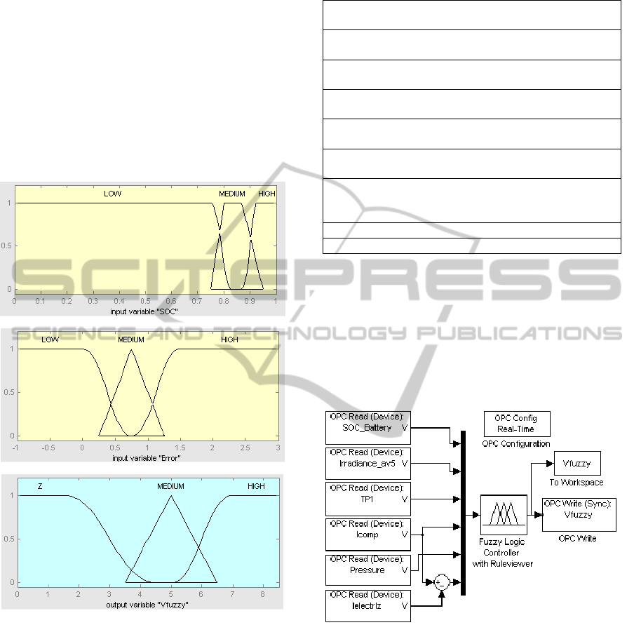
Matlab Membership functions for SOC, error signal
and output variable, Vfuzzy, are presented in Figure
3. Irradiance, compromise current and pressure input
variables have been defined by means of 2 fuzzy
subsets; while SOC, PV module temperature and
error signal use 3 fuzzy subsets. In the case of SOC,
the Low subset has been made larger to avoid
operating on such low values to enlarge the battery
life span.
a)
b)
c)
Figure 3: Membership functions for: a) SOC, b) Error
signal, c) Output signal.
The linguistic variables are Low, Medium and
High for input variables and Z, Medium and High
for output signal. Input ranges depend on the
variable. The narrowest range goes from 0 to 1 for
SOC and the widest one goes from 0 to 1000 W/m
2
for solar irradiance. The range of output signal is 0
to 8’5 V, interval where the electrolyzer behaviour is
lineal. The fuzzy rules define the FLC behaviour.
Table 1 contains the 9 rules that have been
enounced.
Table 1: Rules of the FLC.
If the SOC is High and the irradiance is High and PV
panel temperature is Low then Vfuzzy is High
If the SOC is High and the irradiance is High and PV
panel temperature is Medium then Vfuzzy is High
If the SOC is High and the irradiance is High and PV
panel temperature is High then Vfuzzy is Medium
If the SOC is Medium and the irradiance is High and
PV panel temperature is Low then Vfuzzy is High
If the SOC is Medium and the irradiance is High and
PV panel temperature is Medium then Vfuzzy is High
If the SOC is Medium and the irradiance is High and
PV panel temperature is High then Vfuzzy is Medium
If the SOC is Low or the irradiance is Low or the
compromise current is Low or the pressure is High then
Vfuzzy is Zero
If the error signal is Medium then Vfuzzy is Medium
If the error signal is High then Vfuzzy is High
Figure 4 contains the block diagram of the real-
time control system implemented in Simulink. It
consists of three subsystems: OPC Read blocks for
acquisition of input signals, fuzzy controller block for
control signal generation and OPC Write block for
real-time writing on PLC memory. The
communications parameters are defined with the OPC
Configuration block, so Simulink acts as OPC client.
Figure 4: Simulink block diagram of fuzzy control
scheme.
2.3 WinCC, Simulink and PLC
Integration
Figure 5 shows the sequence of operations from the
reading of sensors connected to PLC. Those values
are stored in data blocks in the PLC memory. The
OPC server of WinCC flexible RT allows the access
to these memory positions from Simulink by means
of the OPC Read blocks. The same happens to data
calculated by the PLC program and accumulated in
its memory. These signals constitute the FLC inputs,
ICINCO2012-9thInternationalConferenceonInformaticsinControl,AutomationandRobotics
18
which applies the defined control rules to the
fuzzyfied inputs in order to generate a signal output,
that is defuzzyfied. This control signal is written in
the PLC memory by the OPC server of WinCC
using the OPC Write block of Simulink. PLC carries
out the conditioning of the signal Vfuzzy and
transfers it to the analog output connected to the dc-
dc converter of the electrolyzer.
Configured blocks of Simulink access to real-
time process variables and the FLC regulates the
electrolyzer operation point.
The sampling time chosen for OPC blocks and
configuration parameters of Simulink is 10 seconds.
The conditioning and un-scaling of the value Vfuzzy
is carried out by the PLC cyclic interruption block
OB35 every 10 sec. This value is sent to the voltage
analogue output of the module SM334. The PLC
programming software STEP7, the supervision
WinCC software and Matlab software are installed
in the same computer. So, the OPC Server and the
OPC Client are both local machines.
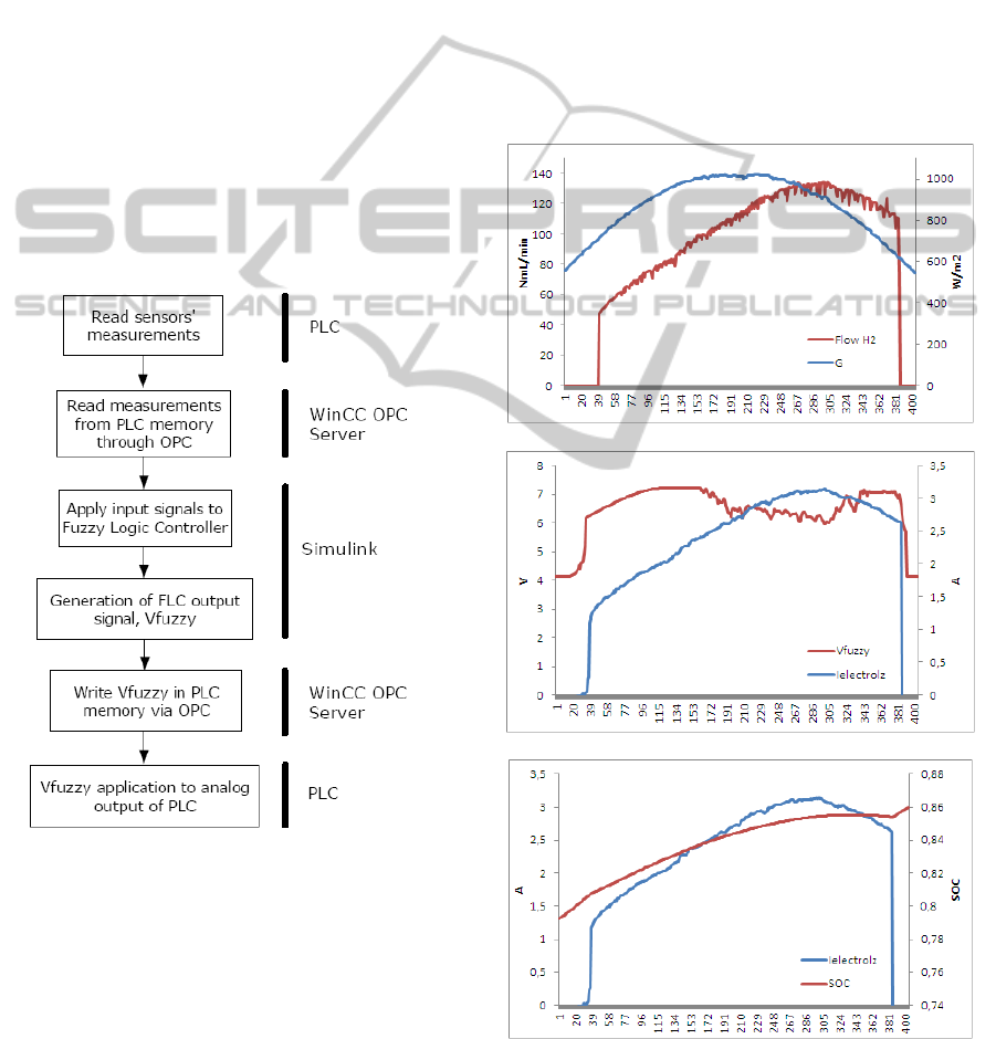
Figure 5: Flowchart of the communication between
WinCC, Simulink and PLC.
3 EXPERIMENTAL RESULTS
The FLC has been tested under real conditions in the
test-bed for several days. The membership functions
and rules were adjusted during trials with different
climatic conditions in order to avoid fluctuations of
the output signal and deviations from the expected
behaviour of the electrolyzer. Figure 6 (a, b and c)
shows the most representative of involved variables
for the system operation during 20
th
February 2012
from 10:00 to 17:00. In Figure 6 a) the irradiation and
the hydrogen production are plotted. In Figure 6 b)
the evolution of the controller output, Vfuzzy, is
shown with the current consumption of the
electrolyzer.
Finally, in Figure 6 c) the battery SOC variation
and the electrolyzer current are shown. As can be
seen, whereas the electrolyzer is producing
hydrogen, the battery SOC is still growing because
the PV modules provide current for both demands.
Low subset has been made larger to avoid operating
on such low values to enlarge the battery life span.
a)
b)
c)
Figure 6: Evolution of: a) incident irradiance and H
2
flow,
b) control signal and electrolyzer current, c) electrolyzer
current and battery SOC for the 20
th
February 2012.
FuzzyControlofaHybridRenewablePowerSystembasedonReal-timeMatlab-PLCCommunicationthroughOPC
19
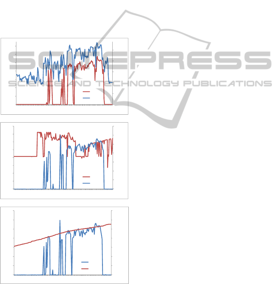
Figure 7 (a, b and c) shows data corresponding to
23rd March 2012 from 10:00 to 13:30, illustrating the
operation of the system during a cloudy day. As can
be seen in Figure 7 a), the hydrogen production
follows the variations of the incident irradiance, so
such production adapts to the power availability. In
Figure 7 b) the effects of the clouds on the output
signal of the FLC, Vfuzzy, and the corresponding
change in the electrolyzer current are showed. Figure
7 c) shows a similar situation to that of 20th February
2012, the battery SOC is incrementing at the same
time that hydrogen is being generated due to the
current delivered by the PV modules. These results
demonstrate the ability of the developed controller to
adjust the control signal to the power availability.
a)
b)
c)
Figure 7: Evolution of: a) incident irradiance and H
2
flow,
b) control signal and electrolyzer current, c) electrolyzer
current and battery SOC for the 23
rd
March 2012.
4 CONCLUSIONS
A fuzzy controller for real-time regulation of the
operation point of a PEM electrolyzer has been
presented. The hydrogen generator constitutes the
core of a hybrid wind-solar test-bed with hydrogen
storage. The fuzzy controller has been designed and
implemented in Simulink and communicated with
the PLC that plays the role of mastermind of the
automation system by means of OPC technology.
The versatility and ability of the proposed
control scheme for being used as a platform for
testing different and advanced control strategies
have been demonstrated and serve as basis for future
works in that sense.
The results under real operating conditions
constitute a proof-of-concept of the validity of the
proposed control structure.
ACKNOWLEDGEMENTS
This work has been supported by grants from
Gobierno de Extremadura (reference GR10157) and
FEDER (Fondo Europeo de Desarrollo Regional,
Una Manera de Hacer Europa)
REFERENCES
Battista, H., Mantz, R. J., Garelli, F., 2006. Power
conditioning for a wind–hydrogen energy system. J.
Power Sources 155, 478–486.
Bilodeau, A., Agbossou, K., 2006. Control analysis of
renewable energy system with hydrogen storage for
residential applications. J. Power Sources 162, 757-764.
Calderón, M., Calderón, A. J., Ramiro, A., González, J. F.,
2010. Automatic management of energy flows of a
stand-alone renewable energy supply with hydrogen
support. Int. J. Hydrog. Energy 35, 2226-2235.
Calderón, M., Calderón, A.J., Ramiro, A., González, J.F.,
González, I., 2011. Evaluation of a hybrid
photovoltaic-wind system with hydrogen storage
performance using exergy analysis. Int. J. Hydrog.
Energy 36, 5751-5762.
Dufo-López, R., Bernal-Agustín, J. L., Contreras, J., 2007.
Optimization of control strategies for stand-alone
renewable energy systems with hydrogen storage.
Renew. Energy 32, 1102–1126.
El-Shatter, T. E., Eskander, M. N., El-Hagry, M. T., 2006.
Energy flow and management of a hybrid
wind/PV/fuel cell generation system. Energy Conv.
Manag. 47, 1264–1280.
Erdinc, O., Elma, O., Uzunoglu, M., Selamogullari, U.S.
Vural, B., Ugur, E., Boynuegri, A.R., Dusmez, S,
2012. Experimental performance assessment of an
0
200
400
600
800
1000
0
20
40
60
80
100
120
140
1
11
21
31
41
51
61
71
81
91
101
111
121
131
141
151
161
171
181
191
W/m2
NmL/min
FlowH2
G
0
0,5
1
1,5
2
2,5
3
3,5
0
1
2
3
4
5
6
7
8
1
11
21
31
41
51
61
71
81
91
101
111
121
131
141
151
161
171
181
191
A
V
Vfuzzy
Ielectrolz
0,74
0,76
0,78
0,8
0,82
0,84
0,86
0,88
0
0,5
1
1,5
2
2,5
3
3,5
1
11
21
31
41
51
61
71
81
91
101
111
121
131
141
151
161
171
181
191
SOC
A
Ielectrolz
SOC
ICINCO2012-9thInternationalConferenceonInformaticsinControl,AutomationandRobotics
20

online energy management strategy for varying
renewable power production suppression. Int. J.
Hydrog. Energy, doi: 10.1016/j.ijhydene.2011.12.042.
Erdinc, O., Uzunoglu, M., 2011. The importance of
detailed data utilization on the performance evaluation
of a grid-independent hybrid renewable energy
system. Int. J. Hydrog. Energy 36, 12664-12677.
Figueiredo, J. M., Sá da Costa, J. M. G., 2008. An
Efficient System to Monitor and Control the Energy
Production and Consumption. Proceedings of the
IEEE 5
th
International Conference on European
Electricity Market, Lisboa, Portugal.
Hajizadeh, A., Aliakbar, M., 2007. Intelligent power
management strategy of hybrid distributed generation
system. Int. J. Electr. Power Energy Sist. 29, 783-795.
Ipsakis, D., Voutetakis, S., Seferlis, P., Stergiopoulos, F.,
Elmasides, C., 2009. Power management strategies for
a stand-alone power system using renewable energy
sources and hydrogen storage. Int. J. Hydrog. Energy
34, 7081-7095.
Jeong, K. S., Lee, W. Y., Kim, C. S., 2005. Energy
management strategies of a fuel cell/battery hybrid
system using fuzzy logics. J. Power Sources 145, 319–
326.
Kyriakarakos, G., Dounis, A., Arvanitis, K., Papadakis,
G., 2012. A fuzzy logic energy management system
for polygeneration microgrids. Renewable Energy, vol.
41, pp. 315-327.
Khan, M. J., Iqbal, M. T., 2009. Analysis of a small wind-
hydrogen stand-alone hybrid energy system. Appl.
Energ. 86, 2429–2442.
Lieping, Z., Aiqun, Z., Yunsheng, Z., 2007. On remote
real-time communication between MATLAB and PLC
based on OPC technology. Proceedings of the 26
th
Chinese Control Conference, Hunan, China.
Linlin, Q., Ping, L., Hongxing, L., 2011. Compound Fuzzy
PID level control system based on WinCC and
MATLAB. International Conference on Measuring
Technology and Mechatronics Automation, Shanghai,
China.
Lu, D., Fakham, H., Zhou, T., François, B., 2010.
Application of Petri nets for the energy management
of a photovoltaic based power station including
storage units. Renew. Energy 35, 1117–1124.
Manoj, R., Janaki, S., 2011. Fuzzy adaptive PID for flow
control system based on OPC. International Journal of
Computer Applications.
Mingliang, W., Mingyong, W., Jiankang, H., Ling, S.,
2011. Intelligent control system of water level for
boiler drum based on OPC and MATLAB.
Proceedings of the 30
th
Chinese Control Conference.
Yantai, China.
Nema, P., Nema, R. K., Rangnekar, S., 2009. A current
and future state of the art development of hybrid
energy system using wind and PV-solar: A review.
Renew. Sust. Energ. Rev. 13, 2096-2103.
Piller, S., Perrin, M., Jossen, A., 2001. Method for state-
of-charge determination and their applications. J.
Power Sources 96, 113-120
Stewart, E. M., Lutz, A. E., Schoenung, S., Chiesa, M.,
Keller, J.O., Fletcher, J., et al., 2009. Modeling,
analysis and control system development for the
Italian hydrogen house. Int. J. Hydrog. Energy 34,
1638-1646.
Uzunoglu, M., Onar, O. C., Alam, M. S., 2009. Modeling,
control and simulation of a PV/FC/UC based hybrid
power generation system for stand-alone applications
Renew. Energy 34, 509–520.
Valenciaga, F., Puleston, P. F., 2005. Supervisor Control
for a Stand-Alone Hybrid Generation System Using
Wind and Photovoltaic Energy. IEEE Transactions on
Energy Conversion, vol. 20, no. 2.
Wu, W., Xu, J. P., Hwang, J. J., 2009. Multi-loop
nonlinear predictive control scheme for a simplistic
hybrid energy system. Int. J. Hydrog. Energy 34
(2009) 3953-3964.
Zervas, P. L., Sarimveis, H., Palyvos, J. A., Markatos,
N.G.C., 2008. Model-based optimal control of a
hybrid power generation system consisting of
photovoltaic arrays and fuel cells. J. Power Sources,
vol. 181, pp. 327–338.
FuzzyControlofaHybridRenewablePowerSystembasedonReal-timeMatlab-PLCCommunicationthroughOPC
21
