
A Light-weight Tool Integration Approach
From a Tool Integration Model to OSLC Integration Services
Weiqing Zhang
1
, Birger Møller-Pedersen
1
and Matthias Biehl
2
1
Department of Informatics, University of Oslo, Oslo, Norway
2
Machine Design Department, Royal Institute of Technology, Stockholm, Sweden
Keywords:
Tool Integration, Tool Metamodel, Integration Model, Adaptor, Artifact.
Abstract:
Existing tool integration approaches integrate various tools directly through tool proprietary APIs. This kind
of integration lacks standardization and are different case by case. Integration based upon common tool
metamodels also turns to be too complicated and hard to maintain. In this paper we provide an approach
which integrates tools based on a combination of tool metamodels and an integration model. Tool element
representatives (Artifacts) are defined to make integrations more standardized and flexible compared to direct
tool APIs. The approach links the tool integration model to the various tool metamodels, and provides
mechanism by which the common integration properties and the various tool metamodels are related. An
industrial case study has been performed to validate the approach with both scenarios of traceability and
exchange of data based upon common data definitions.
1 INTRODUCTION
Tool integration is an important issue in embedded
system development. Development within one tool
typically depends on models and data that are
made within other tools. Tool metamodels define
the constructs and rules for creating models inside
tools. In this paper we provide an approach which
integrates tools based on a combination of tool
metamodels and an integration model that defines tool
element representatives (Artifacts) that are defined
independently of specific tool APIs. Tools create
either models (including implementations in terms
of programs) of a system, or data about models
(e.g. simulation results, impact analysis). Models
are described in modeling languages that are defined
by metamodels. It is therefore attractive to integrate
tools based upon tool metamodels. However, in this
approach we do not use a large, common metamodel
that includes the tool metamodels, but rather a small
integration model that enables the integration.
The main purpose of this paper is to introduce this
tool integration approach and apply it to an industrial
case study, in order to gain experience and improve
the approach itself. The industrial case illustrates
two different tool integration scenarios: traceability
(between requirements and design model elements)
and exchange of commonly defined data between pa-
rts of a system that are made in different languages
and therefore with different tools.
This paper begins with a tool integration
background, and a problem description illustrated
with an industrial case. Then it introduces our tool
integration approach. Section 4 describes a prototype
implemented with this tool integration approach. A
comparison with existing tool integration frameworks
is given in the section 5. Finally, section 6 concludes
the paper.
2 PROBLEM DESCRIPTION
2.1 Background
Embedded systems get more and more widespread,
with tough product requirements related to for
example low cost, dependability, performance,
flexibility and ease of use. This has the tendency
to increase the number of functionalities in the
embedded systems. The systems become complex
because of functional dependencies, shared resources
and conflicting requirements. As a result, the
development process of embedded systems involves
a large number of different tools that are specialized
for certain tasks (e.g. requirements engineering,
137
Zhang W., Møller-Pedersen B. and Biehl M..
A Light-weight Tool Integration Approach - From a Tool Integration Model to OSLC Integration Services.
DOI: 10.5220/0004024801370146
In Proceedings of the 7th International Conference on Software Paradigm Trends (ICSOFT-2012), pages 137-146
ISBN: 978-989-8565-19-8
Copyright
c
2012 SCITEPRESS (Science and Technology Publications, Lda.)
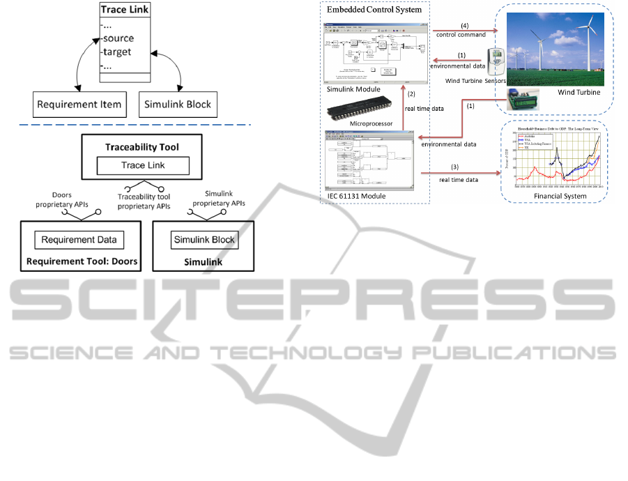
Figure 1: Implement traceability with API approach.
modeling of software and hardware functionality, test
case maintenance, etc.). The models and data of a
project is therefore distributed over different tools that
are seldom designed to be integrated. However, the
models and data handled by the separate tools are
related and must be kept consistent, and developers
also need to establish well-functioning tool chains
tailored to fit product characteristics and business
concerns. There is thus a need for a tool integration
approach.
2.2 Integration by Means of APIs
The most direct tool integration approach is that tools
work with each other through their proprietary APIs.
Here we use the traceability scenario as an example
to illustrate how it works.
Traceability is the ability to logically relate two or
more Artifacts of the product lifecycle, e.g. matching
requirements with models or part of models, source
code implementations, test cases, and verification and
validation activities results. It is required for impact
analysis of any system change, such as adding new
requirements into the system.
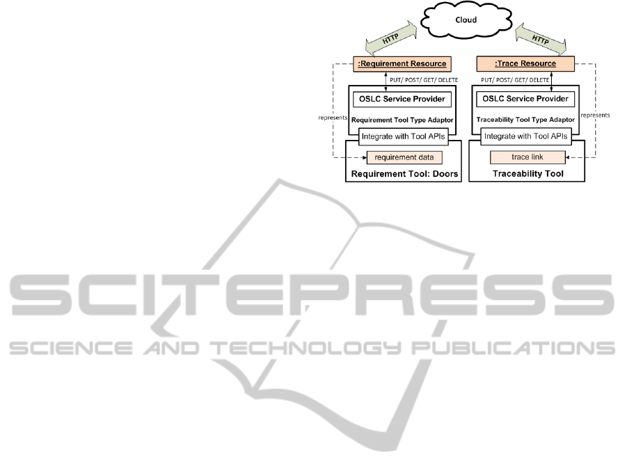
In order to simplify the problem, we assume that a
trace link only contains two main properties, ”source”
and ”target”. As shown in Figure 1, the source
property links to a data inside a requirement tool
(e.g. IBM Doors), while the target property links to
a Block model inside a Simulink model. The links
are established through direct tool proprietary APIs,
which enable the integration among the traceability
tool, the requirement tool, and the Simulink tool.
Integration directly based on tool proprietary
APIs is easy to implement, but also has its obvious
Figure 2: Industrial case description.
deficiencies. The integration heavily depends on
tools’ specific APIs which are constrained by tools’
internal way of handling their model or data elements.
This makes the integrations different case by case.
Assume we want to use another requirement tool
like IRQA to replace the existing Doors, then
the integration between the traceability tool and
requirement tool has to be done again. With the
shortcomings of the API approach such as lack of
standardization, it is hard to maintain development
tool chains that may replace some of their tools.
Moreover, the tool integrations with only direct
proprietary APIs do not provide any added value for
complicated integration cases. E.g., when different
software development lifecycle data are integrated,
there are common features or properties that may be
used to facilitate integrations.
2.3 Industrial Case
In order to illustrate the problem and the solution
based on our approach, we use a concrete embedded
system development case from industry. Figure 2
shows the development context for a wind turbine
embedded control system. There are sensors
that collect the wind turbine environmental data
periodically and transmit it to the embedded control
system. The control system then will generate
commands to control the wind turbine rotation.
The embedded system contains two modules
that execute on the same microprocessor, Simulink
module for high speed performance and IEC 61131
module (Rzonca et al., 2007) for low speed
performance. Both Simulink and IEC 61131 modules
receive real time inputs from sensors. The IEC 61131
module then produces outputs for both the Simulink
module and a remote financial system. Meanwhile,
the Simulink module receives the sensor data and the
real time data from the IEC 61131 module, and use
ICSOFT2012-7thInternationalConferenceonSoftwareParadigmTrends
138
them as inputs to generate commands to control the
wind turbine. The Simulink module uses the real time
data such as temperature values from the IEC 61131
module. These values may be in different units, such
as in Fahrenheit or Centigrade. Engineers expect that
these shared data can be easily understood by both
systems.
A set of tools are involved to develop the control
system. For instance, engineers normally address
requirements in a requirement tool first, then design
the IEC 61131 models and Simulink models, and
subsequently create the traces accordingly. A UML
modeling tool is also used here to specify things that
are common to Simulink and IEC 61131 modules.
Two main tool integration scenarios are described:
traceability between requirements and models, and
transformation of a common data definition (in UML)
into models (in two different languages, Simulink and
IEC 61131) of two parts of a system that have to
exchange data. The above tools are expected to be
integrated to help the two scenarios.
3 A MODEL-BASED
INTEGRATION APPROACH
In the following we shall see that tool integration
based upon an integration model and corresponding
adaptors for each tool will have the desired features:
be more flexible to facilitate tool replacements in the
tool chain compared to the direct tool specific APIs
integration, and provide added values for various tool
integration cases.
3.1 Key Concepts
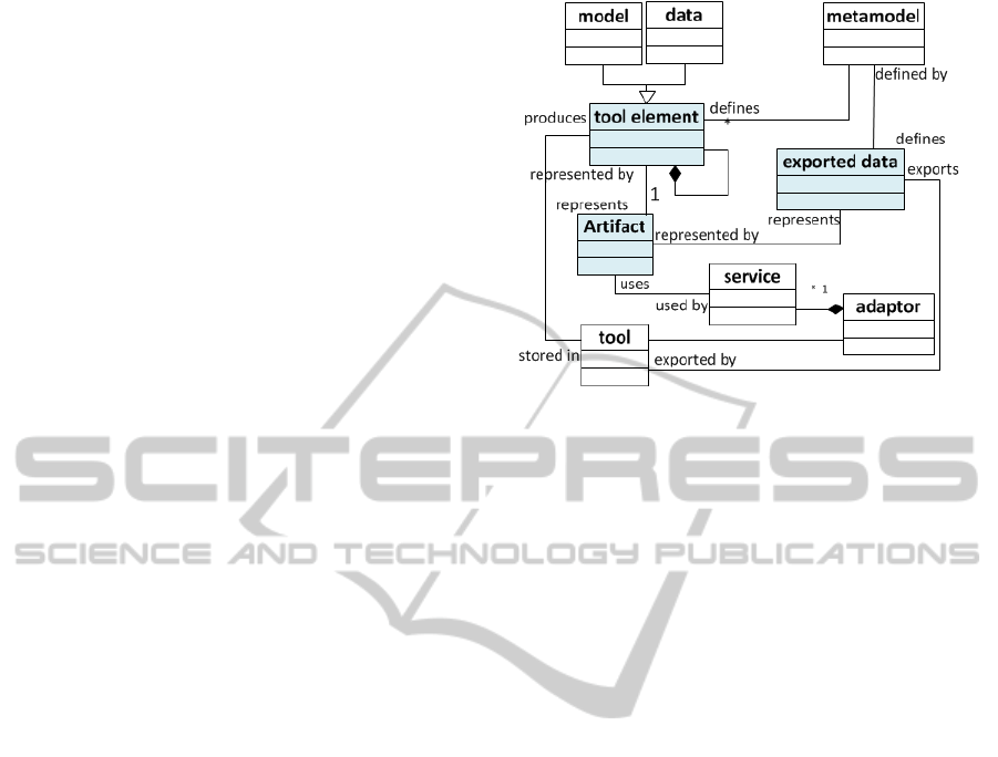
Figure 3 introduces the key concepts of the approach
and their relations.
Tool models/data are the real tool elements that are
produced and manipulated by tools internally, such
as a whole UML model inside Rhapsody. Internal
elements may be exported by tools in standardized
interchange formats. The standardized interchange
formats are different for different languages or data
structures, such as XMI data for Rhapsody UML
model, or a ReqIF data for requirement data.
Metamodel is used to define the tool internal
models or data, as well as the exported data in
standardized interchange formats. However, due to
the reason that tool internal metamodels are usually
only known by tool vendor themselves, we are more
interested in how tool elements may be handled
outside the tools, rather than how tools maintain their
models internally.
Figure 3: Key concepts of the tool integration approach.
For the purpose of integration we define
representatives, named Artifacts, of the above real
tool internal elements, or of exported models/data.
Tools that handle elements defined by the same tool
metamodel are integrated based upon the same kinds
of Artifacts. For example, different UML tools
like Papyrus, MagicDraw, and Rhapsody use the
same Artifact defined by the OMG UML metamodel.
Artifacts of the same language represent the elements
that belongs to the tools which share the same tool
metamodel definitions.
An adaptor is a layer of software that exposes
a subset of tool functionalities to other tools. A
UML use case diagram may be handled differently
in UML tools like Rational Rhapsody and Papyrus.
The Artifact adaptor is then used to allow the
integration independent of the tool internal way
of handling their elements. An Artifact adaptor
provides/requires services that work on the same
tool Artifacts. An adaptor specification defined by
the standardized tool metamodel may be shared by
many tools, while one tool may also implemented by
various adaptor specifications. When a tool adaptor
specification is based upon a metamodel, then all
tools that implements this adaptor specification may
be replaced by each other. Providing standardized
interface for adaptor of the same language makes the
integrations more generic.
3.2 Use of Artifact for Traceability
One common metamodel of all the tools that merges
all the concepts defined in all the metamodels of
the tools which are to be integrated would be large,
complicated and hard to maintain when tools come
and go. We choose a lighter and more flexible
mechanism by defining an integration model of
ALight-weightToolIntegrationApproach-FromaToolIntegrationModeltoOSLCIntegrationServices
139
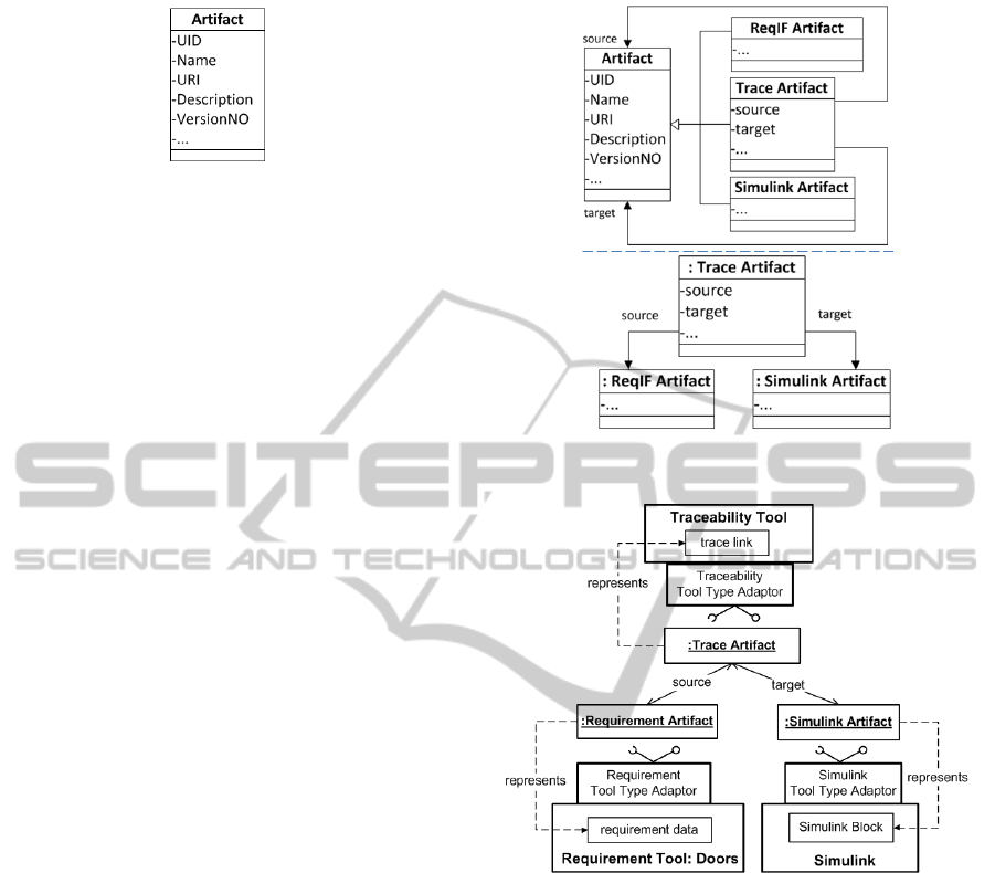
Figure 4: Artifact integration model.
Artifacts to represent tool elements made according
to metaclasses of the tool metamodels.
The Artifact class is the most general concept to
integrate various tool models/data. A class model
is used to define the different types of Artifacts.
An Artifact does not contain the real tool model or
data, but only a set of common properties required
for tool integration purpose such as enabling the
lifecycle management capability. As shown in Figure
4, these common properties include UID (unique
identifier), name, URI of tool element, description,
version number (for lifecycle management), etc..
The Artifact objects can either represent the tool
internal models/data or their exported interchange
data. For example, different UML Artifact objects in
Figure 4 either represent the sequence diagram inside
Rhapsody tool, or the exported UML data in XMI
format.
The elements of the involved tools are defined
based on the tool metamodels or class models. In
the traceability scenario, the ReqIF (Requirements
Interchange Format defined by OMG) metamodel is
chosen as the tool metamodel for the requirement tool
Doors. The Simulink metamodel is an existing tool
metamodel that has been made for other purposes
than tool integration. The traceability tool data is
constructed by a simple class model with only one
class Trace.
We make the class model to describe the
traceability tool data structure, specifically for this
tool integration purpose. As a consequence, we
simply make the Trace class as a subclass of
Artifact, with the purpose of inheriting these common
properties from the Artifact (See Figure 5).
The ReqIF metamodel and Simulink metamodel
are existing metamodels. The ReqIF Artifact and
Simulink Artifact are defended as subclasses of the
Artifact, with additional property that refer to the
metaclasses of ReqIF and Simulink metamodels. In
this way, these specialized Artifacts use the metaclass
from existing metamodels, and their objects represent
the corresponding real tool models/data.
In this way, we have various tool specialized
Artifacts, which are subclasses of Artifact and
manage different kinds of tool metamodels.
Tool specific Artifacts have attributes that are
Figure 5: Artifacts and its objects in traceability scenario.
Figure 6: Approach applied to the traceability scenario.
specific to this tool metamodel. For instance, the
Trace Artifact (in Figure 5) has its own properties
’source’ and ’target’. Its object then has relations with
other Artifact objects, like e.g. a ’source’ relation to
a ReqIF Artifact object and a ’target’ relation to a
Simulink Artifact object. This is possible since both
ReqIF Artifact and Simulink Artifact are specialized
Artifacts and share the same common properties.
Figure 6 shows how trace links between
requirement data and Simulink models are
established by means of Artifacts and adaptors.
Each tool specialized adaptor is based upon its
Artifact definition, such as the Simulink Artifact,
ReqIF Artifact and Trace Artifact classes. Adaptors
generate tool specialized Artifact objects through
adaptor services and use them for integration. The
Simulink model element that shall be traced can
be any object of any metaclass in the Simulink
ICSOFT2012-7thInternationalConferenceonSoftwareParadigmTrends
140
metamodel e.g. a Block, or a System, and the
Simulink model element is represented by the
Simulink Artifact object. A Trace Artifact objects
link to a source Artifact and a target Artifact. The
Simulink Artifact object and the ReqIF Artifact object
represent the real elements within the Simulink and
the requirement tool, respectively, by means of URIs.
The traceability tool traces the data from tools of
Simulink/Requirement language metamodels and is
independent of specific tools.
The Artifact adaptor approach leads to a more
generic tool integration. With Artifact, the
traceability language Adaptor can link to any other
specialized Artifacts as long as they are subclasses
of Artifact and share the same common properties,
and as long as these engineering tools have adaptors
based on these Artifacts and on the same adaptor
specifications.
After having created the Artifact-based integration
models and established their relations to tool
metamodels, we can use these class models to
generate tool adaptor specifications (Biehl et al.,
2012). Artifact objects are used as input and output
parameters for adaptor services. The adaptors are
implemented based upon these generated adaptor
service specifications.
3.3 Use of Artifact for Exchanging
Commonly defined Data
Models and model transformation can help in defining
common data at design time, and then enable
the exchange of data between different parts of a
system at run time. As described in Figure 2,
the two Simulink and IEC 61131 modules need to
exchange commonly defined data, such as the real
time temperature and generator status of the wind
turbine. The exchanged data such as Temperature
is in Fahrenheit unit and Centigrade unit in the
two different modules. The difference between
the definitions of Temperature data type in the two
different modules have to be coped with.
This case is based on a common input and output
data type definition that enables the exchange of data
between the Simulink and IEC 61131 parts of the
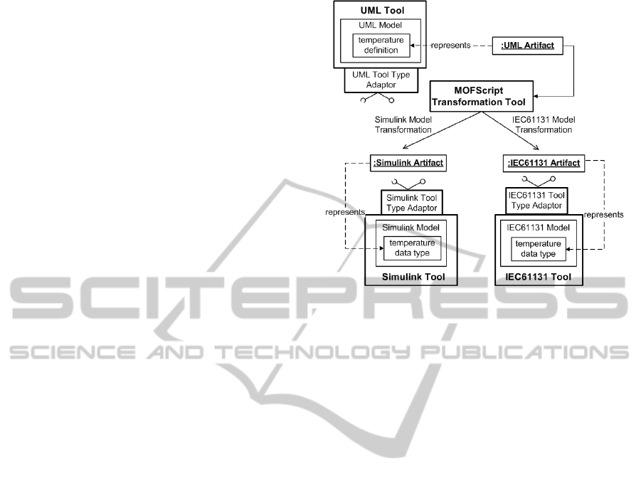
system. From Figure 7, we can see that a common
data type Temperature is defined within a UML class
model in a UML tool. This UML model is represented
by a UML Artifact object. The parts of the system
made in Simulink and IEC 61131 should be able
to exchange Temperature values with different units.
The two parts are represented by the Simulink Artifact
object and IEC 61131 Artifact object. Developers
transform the commonly defined data type based
Figure 7: Approach applied to the exchange data scenario.
on the metamodels of UML, Simulink and IEC
61131. Given predefined metamodels for Simulink
and IEC 61131, the transformations produce two
model elements according to the two metamodels
(for Simulink and IEC 61131), and the adaptors
will then be able to produce the corresponding
real model elements. (Heverhagen and Tracht,
2001)(Vanderperren and Dehaene, 2006).
The tool metamodels required for transformations
are obtained through the property ToolMetamodel,
that is a property of any Artifact that represents
a model element in a language with an existing
metmodel, e.g UML, IEC 61131, and Simulink.
3.4 Tool Integration based upon an
Integration Model
In this section we give an overview of our tool
integration approach.
Artifact is the topmost, most general class of the
integration model.
The above scenarios have demonstrated that trace
links and transformation are required between models
or parts of the models. Artifact in this case refers
to various tool metamodels and its objects are used
to represent these elements. A meta-metamodel is
required to define the structure of valid metamodels,
together with the relations of these metamodels and
corresponding constraints. A shared meta-metamodel
for all tools is used as basis for the exchange of data,
such as Ecore (Sch
¨
atz, 2009) or MOF (Oldevik et al.,
2005).
Figure 8 is an overview of the Artifact model.
When there are existing metamodels, Artifacts are
ALight-weightToolIntegrationApproach-FromaToolIntegrationModeltoOSLCIntegrationServices
141
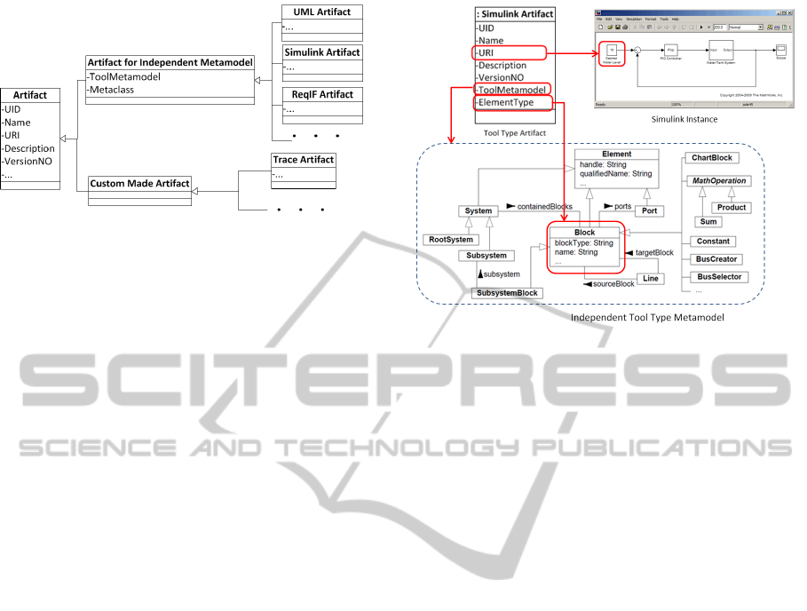
Figure 8: Overview of the artifact model.
used to manage these metamodels. Tool metamodels
are needed as the basis here. There may exist
metamodels for various purposes, rather than only for
tool integration. They can either be standardized or
non-standardized metamodels. As the first choice,
we choose the existing standardized metamodels,
such as the OMG UML metamodel, since these
standardized metamodels are most widely used and
accepted. If there are no standardized metamodels,
we may also choose the existing non-standardized
tool metamodels that made for various purposes.
The objects of Artifact for existing metamodel can
refer to the real tool internal elements and their
representations via the common properties, such as
URI, ToolMetamodel, and Metaclass. With the URI
property, objects of Artifact can represent and access
the corresponding real tool elements, or their exported
models/data. The ToolMetamodel property addresses
the definition of this existing metamodel. The
Metaclass property represents the selected metaclass
of this independent metamodel. Specialized Artifacts
objects representing model elements of the same
language (e.g. UML) will then all have the same
metamodel as their standardized definitions.
When there is no existing metamodel,
custom-made specialized Artifact Classes are
made to describe the data structure of the selected
tools, specifically for the tool integration purpose.
Both the Artifacts for existing tool metamodels
and the custom-made specialized Artifacts are defined
as subclasses of the Artifact class. In this
way the specialized Artifacts inherit the common
properties from Artifact, which provide the lifecycle
management capability.
Figure 9 depicts an example of how a Simulink
Artifact object represents a Block in the Simulink
model according to an existing Simulink metamodel
(Sturmer I., 2007). The URI property gives the
address of the selected Simulink Block element. The
ToolMetamodel property here points to this existing
Simulink metamodel. The Metaclass property
indicates (by means of a metaclasses in the Simulink
Figure 9: Simulink artifact and its object.
metamodel) what kind of element this Artifact
represent (here Block). In the case of Simulink, the
Metaclass property can be any of Element, Block,
ChartBlock, Port, Line, System, etc..
The custom-made class model define the essential
specialized Artifact classes and their relations that
reflect specific domains. As shown in previous Figure
5, a custom-made traceability class model contains
the essential traceability Artifact classes and their
relations.
These tool elements and Artifacts are used as
parameters or results of adaptor services. The
tools within the same language implement their
adaptors based upon the same language adaptor
specifications. In this way, e.g. a testing tool has the
capability to exchange data with all the UML tools
that are built based upon the same UML language
adaptor specification. These UML tool adaptors
provide the same UML Artifact and UML integration
services. Making adaptor based upon the same
language adaptor specification makes the integration
independent of specific tools. Once the testing tool
adaptor is made to integrate with one UML tool
that is compliant with the UML language adaptor
specification, it then can also integrate with the other
UML tools that follow the same language adaptor
specification.
A adaptor builds a bridge between a specialized
Artifact and its corresponding tool element or file.
The services provided by tool adaptors establish
the connections between data that are distributed
in different tools. Language adaptor specifications
define their own specialized Artifacts for the elements
with the same tool language metamodels.
After having created the Artifact models and
established their relations to tool metamodels,
ICSOFT2012-7thInternationalConferenceonSoftwareParadigmTrends
142
it is possible to generate parts of the service
specification through model transformation. The
specification generation is based upon specific
integration scenarios, such as traceability or exchange
commonly defined data.
4 IMPLEMENTATION
Model transformation is used to help the prototype
development. The prototype is implemented based
upon the proposed integration models concepts, in
both the traceability and exchange common data
scenarios.
OSLC (OSLC Community, 2012) is chosen
as an implementation specification to manage the
software lifecycle models/data that are expected to
be integrated together. As an initiative to agree
on the data structure and format used for tool
independent lifecycle management, OSLC provides
mechanism to integrate tools based upon a RESTful
and Service-oriented architecture through standard
HTTP services.
An OSLC Resource is a representative for
real model/data elements that are produced and
maintained by tools, and thus is an obvious
implementation of our Artifacts. Through the specific
OSLC Resources we can manipulate the tool internal
data. An OSLC Resource can be described by a
ResourceShape. A ResourceShape corresponds to a
class of a model, with a set of properties that describes
the data structure of the Resource.
OSLC services and data can be specified by RDF
(Manola and Miller, 2004), which is basically a
data model without type and based upon properties
of objects. Correspondingly we built a data
model for OSLC services and data. Together with
the representative class models, we generate the
tool adaptor specifications through transformation in
terms of OSLC resource specifications, and also part
of the implementation.
The generated tool adaptor specifications include
OSLC Resource and Service specification, which
includes model diagrams and integration information,
such as OSLC property tables, mapping from
tool adaptor integration services to OSLC services
services for identified resources. The RDFs that
enable the OSLC services are produced, such as
Service Catalog, Service Document, and Resource.
Standardized services are generated compliant
to the Artifacts concepts. OSLC services can
manipulate the objects of every class in the Artifact
models through the HTTP Protocol. The OSLC
services provides one more standardized layer above
Figure 10: OSLC implementation architecture.
the tool proprietary APIs, thereby facilitating tool
replacement.
Figure 10 depicts the implementation architecture.
The implementation code can be partially generated
from the above models.
Artifact contains the common properties that
are used for software lifecycle data management
purpose. These common properties correspond to
the OSLC common properties. The Artifact instance
corresponds to the OSLC Resource, which represents
the tool element. Corresponding Java classes that
represent the tool specialized Artifacts are generated
with fragment code. The objects of these classes
represent the tool model/data and they are used as
parameters in run time.
In the traceability scenario, the trace links get the
trace details with the help of Artifact objects. The
Trace Artifact object contains links to the source and
target Artifact, instead of to the real tool elements. As
a result, the trace tools can trace the data from tools of
the same language metamodel and are independent of
specific tools. The source and target Artifacts contain
URIs of their represented data, which allows the Trace
Artifact instances to reach the detailed content from
the real source and target elements.
Adaptor services generated from the traceability
model would look like:
• service to retrieve a number of trace link from a
traceability tool:
TraceArtifact[*] getTrace(String ArtifactUID )
• service to modify a number of trace links from a
traceability tool:
Boolean putTrace(TraceArtifact[*] traceArtifact )
The traceArtifact objects are used as return
parameters in the first services. The real trace link
data is contained in the returned OSLC RDF file.
The above adaptor integration service is mapped to
corresponding OSLC service, such as:
ALight-weightToolIntegrationApproach-FromaToolIntegrationModeltoOSLCIntegrationServices
143

• HTTP GET http://traceServer:8080/
traceArtifact/UID/all?type=realdata
• HTTP PUT http://traceServer:8080/
traceArtifact/UID/trace013
With the Artifact UID property we can locate
the corresponding Artifact (OSLC Resource), and
the pointer to real tool element (URI). The Artifact
property URI identifies its represented tool element,
with which we then can add/ modify/ delete/ query
these represented tool elements.
In the scenario of exchanging common data,
the applications are implemented differently in the
two languages that are defined by two different
metamodels. The IEC 61131 and Simulink models
are defined based on the IEC 61131 and Simulink
metamodels. The models consist of objects of IEC
61131 and Simulink metaclasses, e.g. the Blocks
are objects of the Simulink Block metaclass. The
Simulink Artifact objects and IEC 61131 Artifact
objects represent the models or part of the models
within the Simulink and IEC 61131 tools. The
common exchange data type is defined as a UML
class model, transformed into the two parts to
generate Simulink/IEC 61131 models according to
their respective language metamodels.
MOFScript (SINTEF, 2012) is used to transform
the UML model to corresponding Simulink and IEC
61131 modules. The transformation tool gets the
UML class definition through a UML Artifact object,
and transforms the common data type definition to
fragments of partial models in both Simulink and
IEC 61131 system. The generated Simulink and IEC
61131 model fragments are similarly represented by
Artifacts. In order to perform this transformation, not
only the UML model has to be available, but it is also
required to know the UML metamodel. Similarly,
in order to generate e.g. part of the Simulink
model from the UML model, the transformation
also has to know the Simulink metamodel. The
MOFScript transformation tool accesses the UML
models through UML language Adaptor services.
Here is an example of a Simulink language Adaptor
service:
• Service boolean createSimulinkBlock(
SimulinkArtifact simulinkArtifact )
• HTTP POST http://simulinkServer:8080/
simulinkArtifact/UID/simulink32
With the URI property, the SimulinkArtifact
object simulinkArtifact can access its represented
model element inside Simulink. The Simulink Block
is then created with agreed temperature definition.
After getting the transformed models from the UML
tool, the IEC 61131 module and Simulink module are
able to share the common data.
Compared to the plain tool proprietary API
approach, the Artifact/adaptor approach leads to
more generic tool integration. With the direct API
approach, the traceability tool have to implement
as many different integrations as there are different
engineering tools, since all the proprietary APIs
of these tools are different. The adaptors add
one more standardized integration layer based upon
the proprietary APIs. When new tools are added
into the chain with adaptors that are compliant to
metamodel of the same language, they then can
communicate with other tools through standardized
interface. The approach also facilitates the tool
replacement and lifecycle management issues. It can
generate integration specifications and corresponding
OSLC services through model transformation, then
the specifications and services and can be used in the
implementation to manipulate the Resources (Biehl
et al., 2012).
5 RELATED WORK
Early work of tool integration focuses on identifying
the scope of tool integration in form of aspects
(platform, presentation, data, control, and process
integration) (Wasserman, 1989) and patterns
(integrated tool elements, and process flows pattern)
(Karsai et al., 2005). Model transformation and
semantic integration are addressed as the two key
issues in this domain (Kapsammer et al., 2006).
Tool metamodels are used with different focuses.
The Fujaba (Henkler et al., 2010) approach provides
a generic solution for integrating different tool
data through different metamodel design patterns.
ModelCVS (Kramler et al., 2006) utilizes semantic
technologies and design patters to fill the gaps
between different tool metamodels. Our approach
provides light-weight approaches and enables the
management of different kinds of tool metamodels
(both independently made and custom-made tool
metamodels).
Due to the nature of MDE, approaches like GME
(Bezivin et al., 2005b), VMTS (Mezei et al., 2006)
only focus on the integration of various model-based
design tools, but almost ignore the tools in other
software development phases, such as requirement
tools and testing tools. As a result, lifecycle
management aspect is not covered properly. Our
approaches covers the software lifecycle management
aspect especially.
Existing integration approaches tend to solve
ICSOFT2012-7thInternationalConferenceonSoftwareParadigmTrends
144

the integration problem for a specific aspect.
For instance, the automated framework DUALLY
(Malavolta et al., 2010) allows languages and
tools interoperability through automated model
transformation techniques, but it only focuses on
the architectural languages and ignores other kinds
of languages. (Bezivin et al., 2005a) shows how
MDE approaches may help solving some practical
engineering problems with small Domain Specific
Languages defined by well focused metamodels, but
ignores the usage of huge and rather monolithic
modeling languages like UML 2.0. Some of the
approaches (e.g. MOFLON (Amelunxen et al.,
2008), GeneralStore (Reichmann et al., 2004), CDIF
(Flatscher, 2002), VMTS (Mezei et al., 2006), and
Vanderbilt (Karsai and Gray, 2000) ) are designed
for generic integrations without investigating specific
tool integration scenarios. Our approach is built
based upon concrete scenarios like traceability
and exchange commonly defined data. More
tool integration scenarios such as e.g. baseline
management will be investigated later.
As with WOTIF (Karsai et al., 2006), jETI
(Margaria et al., 2005), and ModelBus (Sriplakich
et al., 2008), our approach also builds the integration
based upon Web Services. However, the usage of
OSLC (Open Services for Lifecycle Collaboration) in
our approach makes the integration more up-to-date
to the latest industrial standard of managing data of
whole software lifecycle.
Compared to the above existing approaches, we
provide a better way to handle tool replacement
issue due to the usage of tool adaptors and
corresponding standardized integration services. The
integration is based upon the standardized defined
type adaptors which are built one more layer above
specific tool proprietary APIs. It implies that
all tool elements are handled in a uniform way,
such as linking a requirement element to a whole
Rhapsody UML model or to elements of a Papyrus
UML model works under the same mechanism.
Moreover, the usage of common properties in the
integration models (Artifacts) enhance the capability
of managing the tool data during the software
lifecycle. In our approach the standardization and
lifecycle management capability are emphasized.
6 CONCLUSIONS
It has been demonstrated that it is possible to
make a light-weight integration model for the
purpose of integrating tool metamodels and providing
value-added integration properties, even in the cases
where these tool metamodels are made independently
of tool integration, instead of a common, merged
metamodel. The approach has been applied to an
industrial case study. It has been proved that our
approach works for as diverse integration scenarios as
traceability between Artifacts, where very little has to
be known about the real traced model elements, and
transformation from commonly defined data in one
language to corresponding data definitions in other
languages, involving the full metamodels of these
languages in order to perform the transformation. The
standardization and lifecycle management capability
for integrating various tools are emphasized in the
proposed approach.
ACKNOWLEDGEMENTS
The research leading to these results has received
funding from the ARTEMIS Joint Undertaking under
grant agreement no.100203, and from the University
of Oslo and ABB CRC (Norway). The authors would
like to thank for the support given by ARTEMIS Tool
Integration project iFEST (iFEST Project, 2012) and
its partners from @pportunity, Atego, KTH, Sodius,
and Tecnalia. We would also like to thank Kai Hansen
from ABB CRC (Norway) to provide the industrial
case and valuable feedback.
REFERENCES
Amelunxen, C., Klar, F., K
¨
onigs, A., R
¨
otschke, T., and
Sch
¨
urr, A. (2008). Metamodel-based tool integration
with moflon. In Proceedings of the 30th international
conference on Software engineering, ICSE ’08, pages
807–810, New York, NY, USA. ACM.
Bezivin, J., Bruneli
´
ere, H., Jouault, F., and Kurtev,
I. (2005a). Model engineering support for tool
interoperability. In Workshop Model Transformations
in Practice, collocated with MoDELS 2005.
Bezivin, J., Brunette, C., Chevrel, R., Jouault, F., and
Kurtev, I. (2005b). Bridging the generic modeling
environment (gme) and the eclipse modeling
framework. In In Proceedings of the OOPSLA
Workshop on Best Practices for Model Driven
Software Development.
Biehl, M., El-Khoury, J., and T
¨
orngren, M. (2012).
High-Level Specification and Code Generation for
Service-Oriented Tool Adapters. In Proceedings of the
International Conference on Computational Science
(ICCSA 2012).
Flatscher, R. G. (2002). Metamodeling in
eia/cdif—meta-metamodel and metamodels. ACM
Trans. Model. Comput. Simul., 12:322–342.
ALight-weightToolIntegrationApproach-FromaToolIntegrationModeltoOSLCIntegrationServices
145

Henkler, S., Meyer, J., Sch
¨
afer, W., von Detten, M., and
Nickel, U. (2010). Legacy component integration
by the fujaba real-time tool suite. In Proceedings
of the 32nd ACM/IEEE International Conference on
Software Engineering - Volume 2, ICSE ’10, pages
267–270, New York, NY, USA. ACM.
Heverhagen, T. and Tracht, R. (2001). Integrating
uml-realtime and iec 61131-3 with function block
adapters. In ISORC, pages 395–402. IEEE Computer
Society.
iFEST Project (2012). iFEST - industrial
Framework for Embedded Systems Tools.
ARTEMIS-2009-1-100203, 2010.
Kapsammer, E., Reiter, T., and Schwinger, W. (2006).
Model-based tool integration - state of the art
and future perspectives. Proceedings of the
3rd International Conference on Cybernetics and
Information Technologies Systems and Applications
CITSA 2006, pages 1–7.
Karsai, G. and Gray, J. (2000). Component generation
technology for semantic tool integration. 2000
IEEE Aerospace Conference Proceedings Cat
No00TH8484, pages 491–499.
Karsai, G., Lang, A., and Neema, S. (2005). Design
patterns for open tool integration. Software and
System Modeling, pages 157–170.
Karsai, G., Ledeczi, A., Neema, S., and Sztipanovits, J.
(2006). The model-integrated computing toolsuite:
Metaprogrammable tools for embedded control
system design. In Computer Aided Control
System Design, 2006 IEEE International Conference
on Control Applications, 2006 IEEE International
Symposium on Intelligent Control, 2006 IEEE, pages
50 –55.
Kramler, G., Kappel, G., Reiter, T., Kapsammer, E.,
Retschitzegger, W., and Schwinger, W. (2006).
Towards a semantic infrastructure supporting
model-based tool integration. In Proceedings of the
2006 international workshop on Global integrated
model management, GaMMa ’06, pages 43–46, New
York, NY, USA. ACM.
Malavolta, I., Muccini, H., Pelliccione, P., and
Tamburri, D. (2010). Providing architectural
languages and tools interoperability through model
transformation technologies. IEEE Trans. Softw.
Eng., 36(1):119–140.
Manola, F. and Miller, E., editors (2004). RDF
Primer. W3C Recommendation. World Wide Web
Consortium.
Margaria, T., Nagel, R., and Steffen, B. (2005). jETI:
A Tool for Remote Tool Integration Tools and
Algorithms for the Construction and Analysis of
Systems. Tools and Algorithms for the Construction
and Analysis of Systems, 3440:557–562.
Mezei, G., Juhasz, S., and Levendovszky, T. (2006).
Integrating model transformation systems and
asynchronous cluster tools. pages 307–318.
Oldevik, J., Neple, T., Gronmo, R., Aagedal, J., and
Berre, A.-J. (2005). Toward standardised model to
text transformations. In Hartman, A. and Kreische,
D., editors, Model Driven Architecture C Foundations
and Applications, volume 3748 of Lecture Notes in
Computer Science, pages 239–253. Springer Berlin /
Heidelberg.
OSLC Community (2012). OSLC - Open Services for
Lifecycle Collaboration Core Specification Version
2.0 . http://open-services.net, 2011.
Reichmann, C., K
¨
uhl, M., Graf, P., and M
¨
uller-Glaser, K. D.
(2004). Generalstore - a case-tool integration platform
enabling model level coupling of heterogeneous
designs for embedded electronic systems. In ECBS,
pages 225–232. IEEE Computer Society.
Rzonca, D., Sadolewski, J., and Trybus, B. (2007).
Prototype environment for controller programming in
the iec 61131-3 st language. Comput. Sci. Inf. Syst.,
4(2):133–148.
Sch
¨
atz, B. (2009). In Ga
ˇ
sevi
´
c, D., L
¨
ammel, R., and Wyk,
E., editors, Software Language Engineering, chapter
Formalization and Rule-Based Transformation
of EMF Ecore-Based Models, pages 227–244.
Springer-Verlag, Berlin, Heidelberg.
SINTEF (2012). MOF Model to Text Transformation.
http://www.eclipse.org/gmt/mofscript, 2012.
Sriplakich, P., Blanc, X., and Gervais, M.-P. (2008).
Collaborative software engineering on large-scale
models: requirements and experience in modelbus.
In Wainwright, R. L. and Haddad, H., editors, SAC,
pages 674–681. ACM.
Sturmer I., T. D. (2007). Automated transformation of
matlab simulink and stateflow models. In Proc. of 4th
Workshop on Object-oriented Modeling of Embedded
Real-time System, pages 57–62.
Vanderperren, Y. and Dehaene, W. (2006). From
uml/sysml to matlab/simulink: current state
and future perspectives. In Proceedings of the
conference on Design, automation and test in Europe:
Proceedings, DATE ’06, pages 93–93, 3001 Leuven,
Belgium, Belgium. European Design and Automation
Association.
Wasserman, A. I. (1989). Tool integration in software
engineering environments. In Long, F., editor, SEE,
volume 467 of Lecture Notes in Computer Science,
pages 137–149. Springer.
ICSOFT2012-7thInternationalConferenceonSoftwareParadigmTrends
146
