
Valkyrie: A UML-based Model-driven Environment for Model-driven
Software Engineering
Thomas Buchmann
University of Bayreuth, Universitaetsstrasse 30, 95440 Bayreuth, Germany
Keywords:
Model-Driven Development, UML, MDA, Model Transformations, Code Generation, EMF, Ecore, GMF,
Acceleo.
Abstract:
Model-driven software engineering aims at increasing productivity by replacing conventional programming
with the development of high-level models. Over the years, UML has been established as a standard modeling
language which is supported by a large number of tools. Unfortunately, many of these tools primarily focus on
graphical editing of diagrams and lack sophisticated support for code generation. The Valkyrie environment
addresses this shortcoming. While Valkyrie supports requirements elicitation with use case and activity dia-
grams, its main emphasis lies on analysis and design, which are based on package diagrams, class diagrams,
statecharts, and the textual UML Action Language (UAL). Modeling-in-the-large is supported by package
diagrams. Packages are refined into class diagrams. For some class, a statechart may be defined as a protocol
state machine. Finally, a method of a class is defined by an activity diagram or a textual program written in
UAL. From these artefacts, Valkyrie may generate fully executable code from a platform independent model.
Valkyrie is built not only for, but also with model-driven software engineering. It is based on the Eclipse
UML2 metamodel and makes use of several frameworks and generators to reduce implementation effort. This
paper reports on the current state of Valkyrie, which is still under development.
1 INTRODUCTION
Model-driven software engineering is a discipline
which puts strong emphasis on the development of
higher-level models rather than on source code. Over
the years, UML (OMG, 2010b) has been established
as the standard modeling language for model-driven
development. It covers a wide range of diagrams
which can be classified into diagrams for (a) struc-
tural modeling (e.g. package diagrams or class dia-
grams) and (b) behavioral modeling (e.g. activity di-
agrams or statecharts). Executable code may be ob-
tained by generating code from behavioral models.
Only then model-driven development is supported in
a full-fledged way.
The basic idea behind UML is providing a stan-
dardized modeling language for the Model-Driven Ar-
chitecture (MDA) (Mellor et al., 2004) approach prop-
agated by the Object Management Group (OMG).
MDA is the result of a standardization process for
core concepts in model-driven software engineering
focusing on interoperability and portability. Thus,
the MDA approach uses both platform independent
(PIM) and platform specific (PSM) models and it uses
UML to describe both of them. UML itself con-
sists of several parts: (1) The Infrastructure (OMG,
2011c) defines the core of the meta language which
serves as the basis for the architecture, while the (2)
Meta Object Facility (MOF) (OMG, 2011b) defines
a meta-modeling language which uses and extends
the abstract syntax defined in the Infrastructure. (3)
The UML Superstructure (OMG, 2011d) defines all
kinds of UML diagrams and serves as the metamodel
specification for all UML modeling tools. (4) XMI
(XML Metadata Interchange) is intended to serve as
an interchange mechanism between UML tools and
as an input format for code generators or interpreters.
(5) Finally, the Object Constraint Language (OCL)
(OMG, 2012) provides a formal textual syntax based
on concepts of set theory and predicate logic to refine
models with queries and constraints.
The UML superstructure which contains the spec-
ification of both concrete and abstract syntax of all
supported diagrams, comprises formal and informal
parts. The informal ones leave room for interpreta-
tion for tool developers. As a consequence, almost
every tool puts emphasis on different features.
So far, research on model-driven software devel-
147
Buchmann T..
Valkyrie: A UML-based Model-driven Environment for Model-driven Software Engineering.
DOI: 10.5220/0004027401470157
In Proceedings of the 7th International Conference on Software Paradigm Trends (ICSOFT-2012), pages 147-157
ISBN: 978-989-8565-19-8
Copyright
c
2012 SCITEPRESS (Science and Technology Publications, Lda.)
opment has focused primarily on defining languages
(or metamodels) for structural and behavioral mod-
els and on building code generators (or interpreters)
for these models. Lots of tools exist, which usually
implement only a subset of the diagrams supported
by UML. Furthermore, software engineers are pri-
marily supported in modeling-in-the-small activities.
Valkyrie on the other hand provides sophisticated sup-
port for modeling-in-the-large based on package dia-
grams. While some other tools only provide support
for creating and editing diagrams, others provide ba-
sic support for generating code for the static structure
of the software based on class diagrams. However,
most of the tools fail to generate code for associations.
Valkyrie puts special emphasis on code generation for
associations.
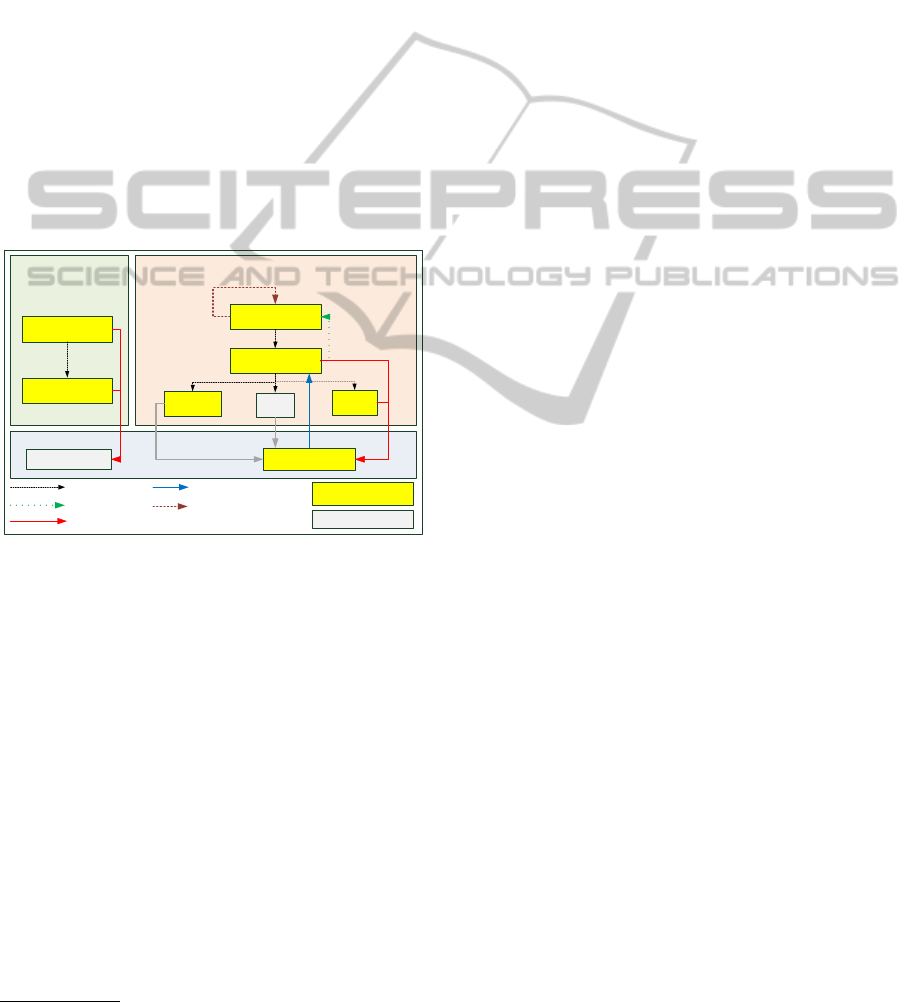
2 OVERVIEW
Requirements
Elicitation
Analysis & Design
Source Code
Use Case
Diagrams
Activity Diagrams
Package Diagram
Class Diagrams
Activity
Diagrams
State
Charts
Application CodeTest Cases
UAL
Refinement
Update
Code Generation
already supported
planned
Reverse Engineering
Refactoring
Figure 1: Diagrams and relations.
As stated in the previous section, the UML specifi-
cation contains formal as well as informal parts. As
a consequence of the room for interpretation left by
the informal parts, each tool developer may put em-
phasis on different aspects of the UML. Due to the
fact that there is no reference implementation by the
OMG, tool developers also have to implement both
the abstract and the concrete syntax of UML. The idea
behind Eclipse UML2
1
is to provide “a useable imple-
mentation of the UML metamodel to support the de-
velopment of modeling tools, a common XMI schema
to facilitate interchange of semantic models and vali-
dation rules as a means of defining and enforcing lev-
els of compliance” (Eclipse Foundation, 2012). In its
current state our tool provides support for the follow-
ing diagrams specified in the UML:
• Use Case diagrams.
1
http://www.eclipse.org/modeling/mdt/?project=uml2
• Activity diagrams.
• Package diagrams.
• Class diagrams.
• Statecharts.
Figure 1 shows an overview about the diagrams
currently supported by Valkyrie and their usage in the
different phases of the software engineering process.
Use case diagrams and activity diagrams are used dur-
ing requirements engineering. In that case, activity
diagrams serve as a formalism to further detail sin-
gle use cases. Application engineering is supported
through package diagrams, class diagrams, activity
diagrams and statecharts respectively. Furthermore,
we are currently working on a support for UML Ac-
tion Language (UAL) (OMG, 2010a). UAL is in-
tended to specify the behavior of operations defined
in the class diagram. Furthermore, classes may be re-
fined by statecharts defining a protocol state machine.
In that case, the statechart defines valid states of a
class. The transitions defined in the statechart can be
called from operation implementations. As stated in
section 1, model-driven development implies the gen-
eration of source code. In its current state, Valkyrie
supports code generation from class diagrams and
statecharts. Code generation from activity diagrams
and UML Action Language is planned. A current
master thesis addresses test case generation from use
cases and their refining activity diagrams.
Additional features of Valkyrie are support for re-
verse engineering class diagrams from legacy code
and model refactoring. To be able to use our tool
with legacy projects, reverse engineering capabili-
ties based on the MoDisco (Bruneliere et al., 2010)
framework (c.f. section 3.4) are provided. Thus, the
user can import the static structure of arbitrary Java
projects within the Eclipse workspace as an UML
model. This model serves as a basis for refactorings,
for example. Furthermore, an overview of the archi-
tecture based on package diagrams and correspond-
ing imports can be deducted. In terms of refactor-
ing, our tool assists the developer with several built-
in rules which can be applied on class diagram el-
ements. These rules have been implemented using
ATL (Jouault et al., 2008; Jouault and Kurtev, 2006).
In (Fowler, 1999), the author lists lots of refactorings
that can be applied to source code in order to improve
the overall quality of the software. In the current state
of our class diagram editor, several refactorings that
are described in (Fowler, 1999) are realized as model
transformations expressed in ATL and can be applied
on the model level. The rules comprise for exam-
ple push up or pull down rules for attributes and op-
erations, or rules to extract superclasses and various
ICSOFT2012-7thInternationalConferenceonSoftwareParadigmTrends
148

platform:/resource/MILIntegrator/profile/IMPORT.profile.uml
<Profile> imports
UML
imports
MILImport
UML
dependingElements : Element
base_DirectedRelationship : DirectedRelationship
<Element Import> DirectedRelationship
<Element Import> Package
<Stereotype> MILImport
<Property> dependingElements : Element [0..*]
<Property> base_DirectedRelationship : Directed Relationship
<Extension> DirectedRelationship_MILImport
pathmap://UML_METAMODELS/UML.metamodel.uml
pathmap://UML_PROFILES/Ecore.profile.uml
pathmap://UML_PROFILES/Standard.profile.uml
pathmap://UML_METAMODELS/Ecore.metamodel.uml
pathmap://UML_LIBRARIES/UMLPrimitiveTypes.library.uml
Figure 2: Profile containing the stereotype that is automati-
cally applied to import relationships for traceability reasons.
other rules.
In the following we will discuss the capabilities
of modeling-in-the-large and modeling-in-the-small
as well as the code generation provided by Valkyrie.
2.1 Modeling-in-the-Large
Models for non-trivial problems are still very large
and require sophisticated support for modeling-in-
the-large (B
´
ezivin et al., 2005) – a challenge which
has not yet gained sufficient attention in model-driven
software engineering so far. Our tool provides support
for modeling-in-the-large with the help of package di-
agrams. The package diagram editor allows build-
ing complex package hierarchies and also to define
visibility constraints between packages and contained
items by using package and element imports respec-
tively.
The tool automatically calculates required imports
between model elements located in different pack-
ages and visualizes the results directly within the
package diagram. A check is performed each time
the model changes and if the current change is con-
flicting with the visibility constraints defined in the
package diagram, a corresponding dialog is presented
to the modeler and he/she can either rollback the
change or choose an appropriate import that is in
turn added to the package diagram to restore consis-
tency. Traceability on the level of imports is real-
ized by a stereotype that is automatically applied to
an import relationship. Figure 2 shows the profile
in which the corresponding stereotype MILImport is
defined. It contains the tagged value dependingEle-
ments which defines a reference to arbitrary elements
in the UML model. Depending elements are model
elements which require an import because the target
type is outside the visibility of the owning namespace.
A detailed description of modeling-in-the-large and
how it is realized with package diagrams can be found
in (Buchmann et al., 2011).
Refinement of packages defined in the package di-
agram is realized by class diagrams.
2.2 Modeling-in-the-Small
As stated above, packages can be refined using class
diagrams. Please note that by no means, the mod-
eler is forced to start the modeling process with pack-
age diagrams. Instead, the modeler can start with any
of the provided diagrams. From our own experience,
a good modeling practice is to refine each package
by its own class diagram. Elements defined in pack-
ages other than the one associated with the current
class diagram can be re-used as so called short-cut
elements. Class diagrams can be refined by state-
charts in order to add custom behavior. In its current
state, Valkyrie and the code generation support proto-
col statecharts only. Behavior for operations defined
in the class diagram can be added by using activity di-
agrams. Current work addresses support for the UML
Action Language to add behavior specification for op-
erations based on a platform independent textual syn-
tax.
Our class diagram editor also puts special empha-
sis on associations. In the UML specification, an as-
sociation must have at least two member ends repre-
senting the involved classifiers. In case of navigable
association ends, these ends are either owned by the
opposite classifiers or the association.
The UML Superstructure suggests various presen-
tation options for navigability and ownership. Our
tool makes navigation and its absence completely ex-
plicit, by using x’s for non-navigable ends and ar-
rows for navigable ones. Bi-directional associations
have arrows decorating each member end. Owner-
ship of association ends by an associated classifier is
indicated graphically by a small filled circle, as sug-
gested in the UML specifictiaon. The absence of the
filled circle indicates end-ownership by the associa-
tion. Both navigability and ownership have impact on
the generated source code. A description can be found
in the corresponding subsection.
Existing classifiers (which are e.g. part of a used
framework) can be imported as a reference to the cur-
rent model to be able to use them in the modeling
process. A special stereotype is applied to referenced
elements. This is important for the code generation
process (see subsection below).
Valkyrie:AUML-basedModel-drivenEnvironmentforModel-drivenSoftwareEngineering
149
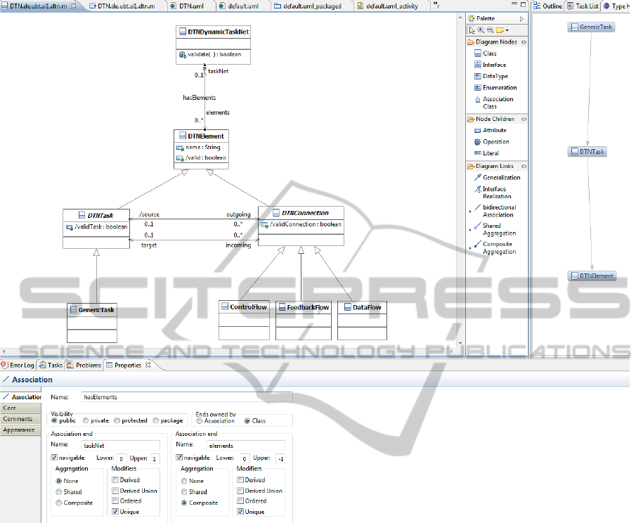
Figure 3: Screenshot of our class diagram editor.
2.3 Code Generation
In its current state, our tool provides full code genera-
tion for Java source code based on class diagrams and
statecharts. The MDA approach (Mellor et al., 2004)
proposes the use of platform-independent (PIM) and
platform-specific (PSM) models. The platform-
specific ones serve as an input for the code gener-
ation. We follow this approach by using model-to-
model transformations to derive the platform-specific
model. This is required because the target language
might not support the same constructs as the model-
ing language does. A prominent example is multi-
ple inheritance in Java. Java only supports multiple
inheritance between interfaces whereas UML allows
multiple inheritance between any kinds of classifiers.
Thus, our class diagram editor allows multiple inher-
itance also for classes. In order to generate code from
class diagrams with multiple inheritance, the multiple
inheritance has to be resolved and mapped onto
multiple inheritance between interfaces instead. In
Valkyrie, the platform-independent model is edited by
the user to model the software system. When the code
generation is invoked, a platform-specific model is
temporarily generated using a model-to-model trans-
formation. The final model-to-text transformation is
then executed on this platform-specific model.
As stated above, navigability and ownership affect
the generated code. Our code generator does not only
create properties with the respective type and cardi-
nality in the corresponding Java classes, it also pro-
vides a set of accessor methods to allow easy access
to associations. In case of bi-directional navigability,
the source code contains mechanisms to ensure the
referential integrity of the model instance at runtime.
This means, that once an association end is set, its op-
posite end is automatically set as well.
In case the association end is owned by a clas-
ICSOFT2012-7thInternationalConferenceonSoftwareParadigmTrends
150

1 package de . ubt . ai1 . dtn . mode l ;
2
3 public class DT N D y n a m i c T a s k N e t {
4 . ..
5 private Set < D T N El e men t > el e m e n t s = new
Ha sh Se t < D TN E l em e nt >() ;
6
7 public Set < D T N El e me n t > g etE l e m e n t s () {
8 return this. el e m ent s ;
9 }
10
11 public void ad d T o E l e m e nts ( DT N E l e m ent
ne w V a l u e ) {
12 if ( n e w V a l ue != null) {
13 this. el e m ent s . ad d ( n e w Val u e ) ;
14 ne w V a l u e . s e t T a s k N e t (this);
15 }
16 }
17
18 public void re m o v e F r o m E l e m e n t s ( D T N Ele m e n t
va l ue ) {
19 if ( v a lu e != null) {
20 this. el e m ent s . r em o v e ( v a lue ) ;
21 va l ue . s e tTa s k N e t (null) ;
22 }
23 }
24
25 public int si z e O f E l e m e n t s () {
26 return this. el e m ent s . si z e () ;
27 }
28
29 public boolean co n t a i n s E l e m e n t s ( DTN E l e m e n t
va l ue ) {
30 return this. el e m ent s . c o nt a i n s ( va lue ) ;
31 }
32
33 public Set < D T N El e me n t > g e t AllE l e m e n t s () {
34 return j av a . u t il . C o l l ec t i o n s .
unm o d i f i a b l e S e t (this. e lem e n t s ) ;
35 }
36 . ..
37 }
Listing 1: Cutout of the generated code for the class
diagram shown in Figure 3.
sifier, a property with corresponding type and cardi-
nality is created in the respective Java class. On the
other hand, if the association end is owned by the as-
sociation itself, a Java class is generated for the as-
sociation containing properties and accessors for all
ends that are owned by this association. Listing 1
shows a cut-out of the generated Java code for the
class DTNDynamicTaskNet depicted in the class di-
agram shown in Figure 3. The cut-out shows how the
corresponding association end elements is mapped to
Java source code. A private attribute named elements
of type Set< DTNElement> is created as well as pub-
lic accessors for it. Since the opposite end of the cor-
responding association in the class diagram is naviga-
ble as well, referential integrity has to be preserved
at runtime. Thus, the opposite end is kept in sync in
the add and remove methods respectively. Further-
more, upper bounds of association ends are taken into
account as well (not shown in the example above).
Please note, that the code generation for upper bounds
is configurable and can be switched on or off on de-
mand.
In case of imported references (as described
above), the code generation is omitted for elements
with the corresponding stereotype. Nevertheless,
these elements can participate in bi-directional as-
sociations using the mechanism described above:
The corresponding association end, which determines
navigability from a referenced element to a element
which is defined in the model, is owned by the associ-
ation and not by the referenced classifier. As a conse-
quence, an additional Java class is created for the as-
sociation which provides the navigation capabilities.
If the member end were owned by the referenced clas-
sifier, bi-directional navigability would imply chang-
ing the code of (3rd party) frameworks which is not
always possible or desired. Association classes are
also used for associations which consist of more than
two member ends. In that case, the association ends
are always owned by the association class. Corre-
sponding accessor methods for all member ends are
created.
Code generation from statecharts is realized with
the help of SMC – The State Machine Compiler
2
.
SMC is able to generate state machine code for var-
ious target languages including Java from a textual
definition. The generated Java code complies to the
state pattern (Gamma et al., 1994). The code genera-
tor provided with Valkyrie uses a model-to-text trans-
formation to generate a textual description of state-
charts which can be read by SMC. A temporary SMC
input file is generated and the SMC compiler is in-
voked using its Java API. The resulting Java code
is seamlessly integrated into the Java code generated
from the class diagrams.
3 IMPLEMENTATION
Valkyrie does not only provide support for model-
driven development, the development of Valkyrie it-
self was performed in a model-driven way. Figure 4
depicts core parts of Valkyrie’s architecture and the
model-driven frameworks it is based on. The basis
for both the metamodel as well as for the used frame-
works is the Eclipse Modeling Framework (EMF)
2
http://smc.sourceforge.net/
Valkyrie:AUML-basedModel-drivenEnvironmentforModel-drivenSoftwareEngineering
151

Eclipse Modeling Framework (EMF)
Graphical Modeling
Framework (GMF)
Acceleo (M2T) ATL (M2M)
Eclipse
UML2
Meta-
model
Valkyrie
Diagram Editors
Code Generation
Reverse
Engineering,
Refactoring, PIM
-> PSM
instance of
works
on
based on
based on
based on
based on
based on
based on
Figure 4: Architecture and used frameworks.
(Steinberg et al., 2009). As already stated in section 2
we use the Ecore-based implementation of the UML
metamodel (Eclipse Foundation, 2012). This offers
several advantages:
Eclipse Integration. A tight integration into the
Eclipse framework is realized.
Data Exchange. An exchange of the underlying se-
mantic models between our tool and other Eclipse
based UML diagram editors (e.g. Topcased, UML
Lab, Papyrus, etc.) is easily possible.
Model-driven Approach. Ecore based frameworks
for concrete syntax development and model-
transformations are available. Thus, Valkyrie has
been implemented in a model driven way: The
diagram editors are based on GMF, the model-
to-model and model-to-text transformations are
based on ATL and Acceleo respectively as shown
in figure 4.
Focus on Concrete Syntax. Tool developers can fo-
cus on concrete syntax development. The abstract
syntax and model validation is provided by the
Eclipse UML2 project.
3.1 Concrete Syntax Development
The concrete syntax of our diagram editors was im-
plemented in a model-driven way using Eclipse’s
Graphical Modeling Framework (GMF)(Gronback,
2009). GMF allows to generate graphical editors
for Ecore models in a model-driven way, by pro-
viding three different types of models that describe
the design and appearance of the graphical elements,
the tools that are part of the editors palette, and a
model which maps the elements of the Ecore model
with their graphical representation and the appropri-
ate palette entries. The GMF code generation uses
these models to generate code for an editor which al-
lows to graphically edit instances of the underlying
model. The generated editors have been extended
with hand-written code to allow interaction between
the different diagram editors and to realize complex
vizualizations or editing operations which could not
be expressed in the GMF models. Although manual
adoptions of the generated code have been required,
there was still a massiv productivity gain using GMF.
Benefits provided by GMF are for example export of
diagrams to various image formats and even to PDF or
automatic layout algorithms which work really well
for class diagrams.
3.2 Model-to-Model Transformations
The Eclipse M2M (model-to-model) project
3
consists
of three independent projects, each of which provides
support for model-to-model transformations: ATL,
operational QVT and declarative (relational) QVT. In
our tool, we use ATL (Jouault et al., 2008) for model-
to-model transformations. Although the OMG pro-
poses QVT (OMG, 2011a) as a standard for model
transformations, ATL seems to be used in much more
projects in the Eclipse context as operational QVT.
Compared to QVT, ATL seems to be more mature,
as it provides debugging support. ATL mixes declara-
tive and imperative approaches and is on a level of ab-
straction which is below pure declarative approaches
like QVT relations (OMG, 2011a) or Triple Graph
Grammars (TGG) (Sch
¨
urr, 1994). ATL offers an API
to execute model transformations programmatically.
We use ATL model transformations for our refactor-
ing rules and to transform the KDM model (which
is the result of a MoDisco reverse engineering step)
into a UML model. Also, ATL is used to derive the
platform-specific model which serves as an input for
the code generation.
3.3 Model-to-Text Transformations
In the context of the Eclipse M2T (model-to-text)
project
4
, three different frameworks for model-to-
text transformations are available: JET (Java Emit-
ter Templates), which is used in the EMF code gen-
eration, Acceleo and XPand. To generate code from
class diagrams and statecharts, we use the Acceleo
5
framework. We chose Acceleo because it is the
only template-based code generation engine in the
EMF context which is based on an official standard:
MOFM2T (MOF Model to Text Transformation Lan-
guage) (OMG, 2008). Like other template languages,
Acceleo contains static and dynamic parts. The dy-
namic parts can be enriched with queries which are
3
http://www.eclipse.org/m2m
4
http://www.eclipse.org/m2t
5
http://www.eclipse.org/acceleo/
ICSOFT2012-7thInternationalConferenceonSoftwareParadigmTrends
152

expressed as OCL constraints. Furthermore, service
classes written in Java can be accessed from those
queries. Acceleo provides an editor for its template
language, which supports code completion and syn-
tax highlighting. Furthermore, an interpreter is pro-
vided, which allows instant testing of code generation
templates on dynamic model instances.
3.4 Text-to-Model Transformations
To provide modeling support for legacy Java projects
we use the MoDisco (Bruneliere et al., 2010) frame-
work to reverse-engineer an UML model from an ex-
isting Java project. MoDisco is used to parse the Java
sources and construct the so called Discovery model.
Afterwards we use our own model-transformation
written in ATL (Jouault et al., 2008) on this interme-
diate model to build the final UML model which is
then used as a basis for visualization with our tool.
3.5 Summary
The model-driven tools around the Eclipse Model-
ing Framework cover all areas which were needed
to develop Valkyrie: abstract syntax development
(the UML2 metamodel based on EMF), concrete
syntax development (the diagram editors based on
GMF), model-to-model transformations (ATL) and
model-to-text transformations (Acceleo). Further-
more MoDisco provides a model-driven and extensi-
ble framework for reverse engineering. Using these
tools resulted in a massive gain of productivity when
developing Valkyrie compared to manual coding.
Therefore, Valkyrie does not only provide support for
model-driven software development, it was also de-
veloped in a model-driven way.
4 RELATED WORK
Numerous tools for UML modeling exist and it goes
far beyond the scope of this paper to name and com-
pare them all. Comparisons can be found in (Eichel-
berger et al., 2009) for example. Therefore, we focus
only on tools that use the Eclipse UML2 metamodel
and do not consider industry-standard tools like Mag-
icDraw
6
or Sparx Enterprise Architect
7
in this paper.
EMF is considered in our comparison, as it is the stan-
dard modeling language in the Eclipse context. Tables
1 and 2 show an overview of the compared tools and
6
https://www.magicdraw.com/
7
http://www.sparxsystems.com/products/ea/index.html
its supported diagrams and code generation capabili-
ties respectively. In the following subsections, a de-
tailed description of each tool is given.
4.1 Rational Software Architect
1 public class DT N D y n a m i c T a s k N e t {
2
3 private Set < DT N M od e l E l eme n t > d T N M o d e l E l e m e n t
;
4
5 public Set < DT N M od e l E l eme n t >
getdTN Mode l E l e m e n t () {
6 // begin-user-code
7 return d T N M o d e l E l e m e n t ;
8 // end-user-code
9 }
10
11 public void se t d T N M o d e l E l e m e n t ( S et <
DT N M o d el E l e m ent > d T N M o d e l E l e m e n t ) {
12 // begin-user-code
13 this. dT N M o d e l E l e m e n t = d T N M o d e l E l e m e n t ;
14 // end-user-code
15 }
16 }
Listing 2: Cutout of the code for the class diagram
shown in Figure 3 generated by Rational Software
Architect.
IBM Rational Software Architect (RSA)
8
is a
heavy-weight tool incorporating the UML for design-
ing architecture of C++ and J2EE application as well
as web services. It is also based on the Eclipse frame-
work and includes capabilities for model-driven de-
velopment with the UML. RSA does not provide sup-
port for modeling-in-the-large with the help of pack-
age diagrams and import relationships. Attributes and
operations can be entered directly within the class
diagram editor following the UML conventions. To
generate code, the modeler first has to create a trans-
formation configuration in which model, target folder
and target language has to be specified. Afterwards
the configuration can be used to generate the source
code. The UML to Java transformation does not pro-
vide support for referential integrity of associations.
E.g. the generated code for the class DTNDynam-
icTaskNet from Figure 3 looks as shown in Listing
2. In terms of end-onwership of associations, RSA
also only supports classifiers as owners of association
member ends.
8
http://www-01.ibm.com/software/rational/-
products/swarchitect/
Valkyrie:AUML-basedModel-drivenEnvironmentforModel-drivenSoftwareEngineering
153
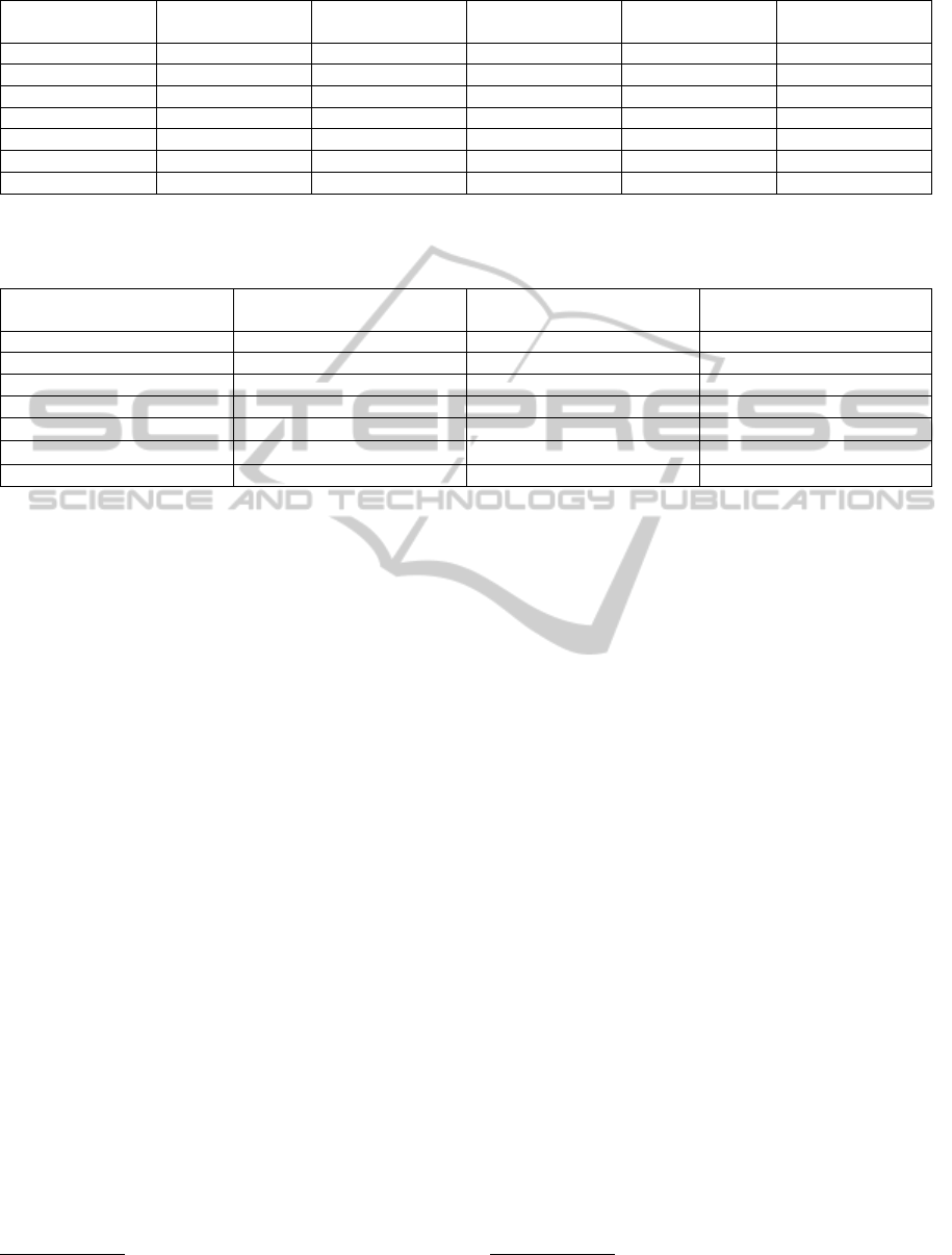
Table 1: Tool comparison: supported diagrams.
package dia-
grams
class diagrams statecharts use case dia-
grams
activity diagrams
RSA + + + + +
Topcased ◦
∗
+ + + +
UML2Tools ◦
∗
+ + + +
Papyrus + + + + +
UML Lab - + - - -
EMF - + - - -
Valkyrie + + + + +
∗
only supported within class diagrams.
Table 2: Tool comparison: code generation features.
static structure advanced association han-
dling
statecharts
RSA + - -
Topcased + - +
UML2Tools - - -
Papyrus - - -
UML Lab + ◦
†
-
EMF + ◦
†
-
Valkyrie + + +
†
upper bounds are not considered, associations may only have two member ends
4.2 Topcased
For many years, Topcased
9
has been the standard
graphical editor for Eclipse UML2 models. Its di-
agram editors are based on the Graphical Editing
Framework (GEF). It provides support for the fol-
lowing diagrams: class diagrams, use case diagrams,
activity diagrams, state machine diagrams, sequence
diagrams, deployment diagrams, composite structure
diagrams and component diagrams. Package dia-
grams are not supported explicitly. Hence, the mod-
eler can create package hierarchies and import rela-
tionships in the class diagram editor. The visibili-
ties defined by these import relationships are not con-
sidered. In the class diagram editor, attributes and
operations have to be entered using mouse and key-
board. First, the respective tool has to be activated
in the graphical editor’s palette and applied to the
desired classifier. Then the attributes of the newly
added element have to be edited using the property
view. Like our tool, Topcased supports code gener-
ation from class diagrams and statecharts. The code
generation can be invoked by right clicking on the se-
mantic model in the Eclipse navigator and choosing
the appropriate entry from the popup menu. How-
ever, in terms of handling associations it provides no
support at all, since associations seem to be omitted
during the code generation process.
9
http://www.topcased.org
4.3 UML2Tools
The UML2Tools project is part of the Eclipse
MDT (model development tools)
10
project. The
UML2Tools project provides a set of GMF-based ed-
itors for viewing and editing UML models. Its fo-
cus lies on (possibly) automatic generation of editors
for all UML diagram types. In its current state, edi-
tors are available for the following diagrams: activ-
ity diagrams, class diagrams, component diagrams,
composite structures diagrams, deployment diagrams,
profile definition diagrams, sequence diagrams, state
machine diagrams and use case diagrams. Like Top-
cased, UML2Tools does not offer a dedicated editor
for package diagrams. Packages can be added to class
diagrams. Building complex package hierarchies is
not possible that way because once a package is added
to the class diagram and a nesting package is added,
the nesting package can not be further refined with
child elements. Attributes or operations can be added
to class diagram elements using the editor’s palette.
Modifying their default names and values is only pos-
sible using the property view. Since the project aims
at providing automatically generated editors, there is
no code generation for UML models designed with
the tool included in the tool distribution.
10
http://www.eclipse.org/mdt
ICSOFT2012-7thInternationalConferenceonSoftwareParadigmTrends
154

4.4 Papyrus
Papyrus
11
is another subproject of the Eclipse MDT
project. It is dedicated to provide an integrated envi-
ronment for editing any kind of EMF-based models
and in particular it supports UML and SysML mod-
els. Furthermore, Papyrus offers advanced support
for UML profiles and enables modelers to create their
own domain specific languages based on UML2 stan-
dards and its extension mechanisms. In addition to
this feature, the user can highly customize the Pa-
pyrus perspective to adopt it to a similar look and
feel as a native DSL editor. Papyrus is shipped with
graphical editors for the following diagrams: Activity
diagrams, class diagrams, communication diagrams,
component diagrams, composite structure diagrams,
deployment diagrams, sequence diagrams, state ma-
chine diagrams, use case diagrams and package dia-
grams. On the level of packages, it allows to build
and visualize complex hierarchies and define import
relationships among package diagram elements. The
visibility constraints defined by those import relation-
ships are not considered during the editing process.
To add attributes or operations to classifiers in the
class diagrams, the user has to activate the corre-
sponding tool in the palette, add it to the diagram
and adjust the respective values using the property
view. Please note that there is another tool named Pa-
pyrus
12
, which also provides support for UML2 mod-
els. It is the predecessor of the current Papyrus project
which is now ran under the Eclipse flag. Since the
”new“ Papyrus does not provide code generation fa-
cilities at the moment, we compared our generated
code to the one that is generated by the ”old“ Pa-
pyrus tool. Its Java code generation is also based on
the Acceleo framework. In terms of treating associa-
tions, the tool just generates attributes to the respec-
tive classes. There is no support for referential in-
tegrity as even accessor methods are missing in the
generated code.
4.5 UML Lab
UML Lab
13
aims to provide support for agile
modeling, custom codegeneration and Roundtrip −
Engineering
NG
. UML Lab puts strong emphasis on
class diagrams, code generation and the user inter-
face. Package diagrams are not supported all. The
user can only add single packages to a class dia-
gram and define imports between them. The visib-
lity constraints defined by these imports are neglected
11
http://www.eclipse.org/modeling/mdt/papyrus/
12
http://www.papyrusuml.org/
13
http://www.uml-lab.com/en/uml-lab/
in class diagrams. Furthermore, the packages which
have been added to the class diagram can not be re-
fined with other contained elements like nested pack-
ages or classifiers. As a result, building complex
package hierarhies is not possible. The user inter-
face comprises classic tools like the palette as well
as gesture recognition, context sensitive hints and
model autocompletion. Support for domain specific
requirements is provided by the UML profile mech-
anism. Using Roundtrip − Engineering
NG
, the mod-
eler can change model and code simultaneously and
changes are automatically propagated between model
and code and vice versa. A template-based approach
is used for reverse engineering which is based on the
work presented in (Bork et al., 2008). Furthermore,
code generation templates for Java and PHP are in-
cluded which can be customized to match specific
coding conventions for example. While the Java code
generation provides support for referential integrity of
bi-directional associations, UML Lab only supports
classifiers as owners of association member ends.
4.6 EMF
The Eclipse Modeling Framework (EMF) (Steinberg
et al., 2009) is based on EMOF (essential MOF)
which contains a subset of MOF (OMG, 2011b). It
provides the user with modeling capabilites for the
static structure using class diagrams. Packages are
supported, but there is no support for defining rela-
tions between them based on import dependencies.
Furthermore, class modeling capabilities are limited
compared to UML. For example, there is no equiva-
lent to associations. Relationships between classifiers
are expressed using references. References are always
directed by default. A bidirectional association can be
simulated by using two references in opposite direc-
tions. EMF provides a Java code generation based
on JET (Java Emitter Templates). It provides support
for referential integrity of references. Furthermore, it
provides support for multiple inheritance. Classes are
always transformed into interfaces and corresponding
implementation classes. Multiple inheritance is real-
ized by interface inheritance.
5 CONCLUSIONS AND FUTURE
WORK
In this paper we presented the current state of
Valkyrie, our modeling environment for UML in
Eclipse. At the moment the following UML diagrams
are supported by our tool: Package diagrams, class
diagrams, use case diagrams, activity diagrams and
Valkyrie:AUML-basedModel-drivenEnvironmentforModel-drivenSoftwareEngineering
155

statecharts. Currently, work is adressed to implement
an editor for object diagrams. Additional diagrams,
which will be implemented in the near future, are se-
quence diagrams and component diagrams. Further-
more, we are working on a mechanism for roundtrip
engineering of UML models and source code which
is inspired by Triple Graph Grammars (Sch
¨
urr, 1994).
It is targeted to allow seamless editing of model and
source code. First results are very promising. An-
other area which is currently covered by a master
thesis is the generation of test cases based on use
case diagrams and activity diagrams. Future exten-
sion to the code generator comprise the support for
derived attributes which can already be expressed in
the class diagram editors using OCL constraints, and
the generation of operation behavior expressed by ac-
tivity diagrams and UML Action Language respec-
tively. UML2 supports extensibility and domain spe-
cific customization via profiles. Future work will
comprise the integration of the profile concept in our
tool. Since we use the Eclipse UML2 meta model
which is based on Ecore, our tool can be easily ex-
tended with research results from other projects at our
chair in the fields of modeling with graph transfor-
mations , the model-driven development of software
product lines and differencing and merging of mod-
els. Finally, our tool is used and evaluated in our un-
dergraduate teaching course Software Engineering I.
ACKNOWLEDGEMENTS
The author wants to thank the following students
for contributing to the implementation of Valkyrie
in various ways (in alphabetical order): Christopher
B
¨
ar, Matthias Kufer, Stefan Matthaei, Stefan Oehme,
Patrick Pezoldt, Alexander Rimer and Frank Wein.
REFERENCES
B
´
ezivin, J., Jouault, F., Rosenthal, P., and Valduriez, P.
(2005). Modeling in the large and modeling in the
small. In Model Driven Architecture, European MDA
Workshops: Foundations and Applications, MDAFA
2003 and MDAFA 2004, volume 3599 of LNCS, pages
33–46, Twente, The Netherlands.
Bork, M., Geiger, L., Schneider, C., and Z
¨
undorf, A. (2008).
Towards roundtrip engineering - a template-based re-
verse engineering approach. In Schieferdecker, I.
and Hartman, A., editors, ECMDA-FA, volume 5095
of Lecture Notes in Computer Science, pages 33–47.
Springer.
Bruneliere, H., Cabot, J., Jouault, F., and Madiot, F. (2010).
Modisco: a generic and extensible framework for
model driven reverse engineering. In Proceedings
of the IEEE/ACM international conference on Auto-
mated software engineering, ASE ’10, pages 173–
174, New York, NY, USA. ACM.
Buchmann, T., Dotor, A., and Westfechtel, B. (2011).
Model-driven software engineering: concepts and
tools for modeling-in-the-large with package dia-
grams. Computer Science - Research and Develop-
ment, pages 1–21. 10.1007/s00450-011-0201-1.
Eclipse Foundation (2012). Model
development tools (mdt).
http://www.eclipse.org/modeling/mdt/?project=uml2.
last visited: 2012/02/27.
Eichelberger, H., Eldogan, Y., and Schmid, K. (2009). A
comprehensive survey of uml compliance in current
modelling tools. In Liggesmeyer, P., Engels, G.,
M
¨
unch, J., D
¨
orr, J., and Riegel, N., editors, Software
Engineering, volume 143 of LNI, pages 39–50. GI.
Fowler, M. (1999). Refactoring: Improving the Design of
Existing Code. Addison-Wesley, Boston, MA, USA.
Gamma, E., Helm, R., Johnson, R., and Vlissides, J.
(1994). Design Patterns - Elements of Reusable
Object-Oriented Software. AW, AWADDR.
Gronback, R. C. (2009). Eclipse Modeling Project:
A Domain-Specific Language (DSL) Toolkit. The
Eclipse Series. AW, Boston, MA, 1st edition.
Jouault, F., Allilaire, F., B
´
ezivin, J., and Kurtev, I. (2008).
Atl: A model transformation tool. Science of Com-
puter Programming, 72(12):31 – 39. Special Issue
on Second issue of experimental software and toolkits
(EST).
Jouault, F. and Kurtev, I. (2006). Transforming models with
atl. In Bruel, J.-M., editor, Satellite Events at the
MoDELS 2005 Conference, volume 3844 of Lecture
Notes in Computer Science, pages 128–138. Springer
Berlin / Heidelberg. 10.1007/11663430 14.
Mellor, S. J., Kendall, S., Uhl, A., and Weise, D. (2004).
MDA Distilled. Addison Wesley Longman Publishing
Co., Inc., Redwood City, CA, USA.
OMG (2008). MOF Model to Text Transformation
Language, Version 1.0. OMG, Needham, MA,
formal/2008-01 edition.
OMG (2010a). Action Language for Foundational UML
(Alf). Object Management Group, Needham, MA,
ptc/2010-10-05 edition.
OMG (2010b). OMG Unified Modeling Language (OMG
UML), Superstructure, Version 2.3. OMG, Needham,
MA, formal/2010-05-05 edition.
OMG (2011a). Meta Object Facility (MOF) 2.0
Query/View/Transformation, v1.1. Object Manage-
ment Group, Needham, MA, formal/2011-01-01 edi-
tion.
OMG (2011b). Meta Object Facility (MOF) Core. Object
Management Group, Needham, MA, formal/2011-08-
07 edition.
OMG (2011c). UML Infrastructure. Object Management
Group, Needham, MA, formal/2011-08-05 edition.
OMG (2011d). UML Superstructure. Object Management
Group, Needham, MA, formal/2011-08-06 edition.
ICSOFT2012-7thInternationalConferenceonSoftwareParadigmTrends
156

OMG (2012). Object Constraint Language. Object Man-
agement Group, Needham, MA, formal/2012-01-01
edition.
Sch
¨
urr, A. (1994). Specification of Graph Translators with
Triple Graph Grammars. In Tinhofer, G., editor, 20th
Int. Workshop on Graph-Theoretic Concepts in Com-
puter Science, volume 903 of Lecture Notes in Com-
puter Science (LNCS), pages 151–163, Heidelberg.
Springer Verlag.
Steinberg, D., Budinsky, F., Paternostro, M., and Merks,
E. (2009). EMF Eclipse Modeling Framework. The
Eclipse Series. AW, Boston, MA, 2 edition.
Valkyrie:AUML-basedModel-drivenEnvironmentforModel-drivenSoftwareEngineering
157
