
Development of Parallel Two-wheel Vehicle with Lower Gravity Center
of Vehicle Body
Yoshiyuki Noda
1
, Yukinori Sago
2
, Kazuhiko Terashima
2
, Kiyoaki Kakihara
3
and
Hirotoshi Kawamura
4
1
Department of Mechanical Engineering, University of Yamanashi, 4-3-11, Takeda, Kofu, 400-8511, Japan
2
Department of Mechanical Engineering, Toyohashi University of Tech.,
1-1, Hibarigaoka, Tempaku, Toyohashi, 441-8580, Japan
3
KER Co., Ltd., 215, Toyogaoka, Toyokawa, 442-0808, Japan
4
Sinfonia Technology Co., Ltd., 150, Motoyashiki, Mitsuya, Toyohashi, 441-3195, Japan
Keywords:
Parallel Two-wheel Vehicle, Lower Gravity Center, Sway Suppression Control of Vehicle Body, Active Mass
Damper, Backstepping Control.
Abstract:
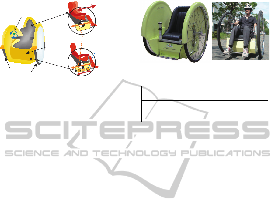
This paper presents an advanced parallel two-wheel vehicle which has lower gravity center of vehicle body.
The gravity center is assigned at the lower position than the wheel axis. Therefore, the vehicle has a structure
of the pendulum, and enables the vehicle body with the passenger to always keep the stable posture, even if
the vehicle is in the power-off or control-off condition. And, 2-DOF joystick which has operation with back-
and-forth direction and rotation is applied to the proposed vehicle. The elderly or handicapped passenger
can operate easily the vehicle by this joystick. Moreover, in order to suppress the sway of the vehicle body
as a pitching oscillation while driving the vehicle, the sway suppression control system with an active mass
damper system is proposed in this paper. The control system is designed by a backstepping method. The
effectiveness of the proposed sway suppression control system with the active mass damper system is verified
by the experiments using the proposed parallel two-wheel vehicle with lower gravity center.
1 INTRODUCTION
In recent years, barrier-free society is advancing, and
welfare environment has been gradually improved.
There have been many studies about an electric
wheelchair as welfare device for elderly and people
with lower physical ability. And the demand for the
electric wheelchair will be increased in the future.
In addition, many researches and developments have
also focused on personal vehicle with low energy re-
quirement, which is required to support for short-
distance transport, (Hun-ok Lim and Tamai, 2008),
(Y. Ueno and Kitagawa, 2009) and (Y. Noda and
Terashima, 2010).
The typical electric wheelchair is drivenwith four-
wheel which is composed of the front casters and the
rear wheels. However since these wheelchairs have
the large turning radius, it is difficult to pass through
in a narrow passage. A parallel two-wheel vehicle
with structure of inverted pendulum, which has small
turning radius, has been developed in recent years,
(M. Sasaki, 2005). In such vehicle, an inverted pen-
dulum control system is used for standing the vehicle
stably by only using the two driving parallel wheels,
(C. Nakagawa and Hirayama, 2011) and (Karkoub
and Parent, 2004). Therefore, the gravity center of
the vehicle body is higher than the wheel axis, and
the vehicle is moved by tilting the vehicle body for-
ward or backward by moving the gravity center. How-
ever, when the vehicle is in the power-off or control-
off conditions which are caused by a breakdownin the
vehicle, the vehicle cannot keep the standing posture.
Moreover, we consider the vehicle with the passen-
ger sitting which can be used by elderly and handi-
capped people. In this case, since the gravity center
is lower than the standing posture, the larger action of
the passenger’s upper body is required for operating
the vehicle. The elderly or handicapped passenger is
difficult to the large action in the vehicle.
Therefore, we propose a parallel two-wheel vehi-
cle with safety and easy operation which can be used
by elderly and handicapped people. The proposed ve-
hicle has the lower gravity center of the vehicle body
as shown in Figure 1. The position of the gravity cen-
70
Noda Y., Sago Y., Terashima K., Kakihara K. and Kawamura H..
Development of Parallel Two-wheel Vehicle with Lower Gravity Center of Vehicle Body.
DOI: 10.5220/0004036400700076
In Proceedings of the 9th International Conference on Informatics in Control, Automation and Robotics (ICINCO-2012), pages 70-76
ISBN: 978-989-8565-22-8
Copyright
c
2012 SCITEPRESS (Science and Technology Publications, Lda.)
2-DOF Joystick with
Forth-and-back and
Turns Operation
Large Diameter Wheels
Active Mass
Damper System
Seat Moving
Move Gravity Center
(Weight Moving)
Vehicle Body
Figure 1: Illustration of parallel two-wheel vehicle with
lower gravity center of vehicle body.
ter of this vehicle with the passenger sitting is lower
than the wheel axis, since the vehicle has the large
diameter wheels and the battery, the actuators and
the control devices are placed under the wheel axis.
Therefore, it allows the vehicle to always stand stably
without electric power supply. And, 2-DOF joystick
with both back-and-forth and rotating operation is ap-
plied to the proposed vehicle for operating easily.
However, when the passenger rides on the pro-
posed vehicle, the vehicle body is leaned by moving
the gravity center due to sit the passenger on the vehi-
cle. In the proposed vehicle, the posture of the vehicle
body with the passenger is compensated by adjusting
automatically the position of the seat with the passen-
ger. Moreover, in order to suppress the sway of the
vehicle body as a pitching oscillation while driving
the vehicle, the sway suppression control system of
the vehicle body is proposed in this paper. In the con-
trol system, an active mass damper system is installed
inside the vehicle body. In the design of the control
system, the vehicle body dynamics is modeled using
Lagrange equation of motion. And, the control sys-
tem of the sway suppression control with the active
mass damper system is designed by a backstepping
method, (Fu and Zao, 2007).
The effectiveness of the proposed sway suppres-
sion control system is verified by the experiments
using the proposed parallel two-wheel vehicle with
lower gravity center.
2 OVERVIEW OF PARALLEL
TWO-WHEEL VEHICLE WITH
LOWER GRAVITY CENTER
The parallel two-wheel vehicle with lower gravity
center consists of two large diameter driving wheels
and the vehicle body where the passenger sits on as
shown in Figure 1. The power-supply, the control de-
Figure 2: Photos of developed two-wheel vehicle.
Table 1: Specification of Vehicle.
Size (m) W0.90×D1.20×H1.70
Mass (kg) 137
Wheel Diameter (mm) 1041
Driving Power (W) 300
Driving Voltage (V) 24
vices and actuators are set on the lower position than
the wheel axis. As a result, the gravity center of this
vehicle with the passenger sitting on the seat is lower
than the wheel axis. Therefore, it allows the vehicle
to always stand stably without electric power supply.
A conventional parallel two-wheel vehicle has high
gravity center of the vehicle body with the passenger,
and an inverted pendulum control system is applied
for stably standing the vehicle body and operating the
vehicle by moving the gravity center of the passenger.
However, in the proposed vehicle, it is difficult to op-
erate the vehicle by moving the gravity center of the
passenger, because the passenger sits on the seat and
the gravity center of the vehicle body is in low posi-
tion. Therefore, the vehicle is operated by the 2DOF
joystick. This joystick has both forth-and-back and
rotating operation. It is easy to operate the vehicle,
since the movement of the joystick is the same as the
movement of the vehicle.
When the passenger sits on the seat of the vehi-
cle, the vehicle body is leaned statically by moving
the gravity center of the vehicle body with the pas-
senger. For compensating the vehicle body leaning,
the seat positioning control system is installed to the
seat supporting structure in the vehicle body. And,
while the vehicle moving, the vehicle body is swayed
by the acceleration of the vehicle. In order to suppress
the vehicle body swaying, the sway suppression con-
trol system with the active mass damper is proposed
in this paper. The sway suppression control system is
located on the bottom of the vehicle body.
The parallel two-wheel vehicle with lower gravity
center developed by the present authors is shown in
Figure 2, and the specification of the developed two-
wheel vehicle is shown in Table 1.
DevelopmentofParallelTwo-wheelVehiclewithLowerGravityCenterofVehicleBody
71
A/D Board
Count Board
D/A Board
Tilt Sensor
Gyro Sensor
PCPC
4ch outputs
6ch inputs
2ch inputs
Drive Weight
12V Battery 4
Joystick
Drive Seat
Drive Wheel
BusBridge
X
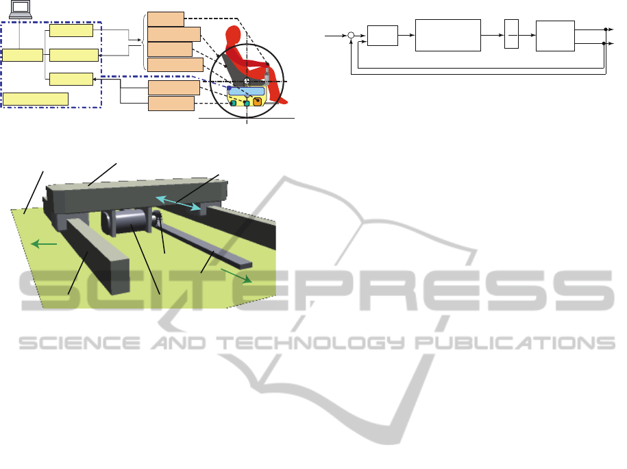
Figure 3: Control system of vehicle.
Pinion
Weight
Motor and Encoder
Linear Slider
Rack
Vehicle Body
Transfer Direction
of Weight
Front of
Vehicle
Right of
Vehicle
Figure 4: Active mass damper system.
2.1 Control Apparatus of Vehicle
The construction of the control system in the paral-
lel two-wheel vehicle is shown in Figure 3. The right
and left wheels are rotated by DC servomotors, re-
ducers and pulley mechanisms. The rotations of the
wheels are detected by the rotary encoders fitted on
the servomotors. The forth-and-back tilting and rotat-
ing of the joystick are detected by the rotary encoders
fitted on each axis. The weight in the active mass
damper system is transferred by DC servomotor, re-
ducer, rack-and-pinion and linear sliders as shown in
Figure 4. The position of the weight is detected by
the rotary encoder fitted on the servomotor. The seat
transfer system is also the same mechanism as the ac-
tive mass damper system. The tilting angle and the
angular velocity of the vehicle body are detected by
the tilt sensor and the gyro sensor respectively located
on the bottom of the vehicle body.
The signals detected by the encoders, the tilt and
the gyro sensors are collected into the PC through the
A/D and the counter boards. Then, the input signals
are added to the servomotors through the D/A board.
3 SEAT POSITIONING CONTROL
SYSTEM
When the passenger sits on the seat of the vehicle, the
vehicle body is leaned by moving the gravity center
of the vehicle body with the passenger. For compen-
sating the vehicle body leaning, the seat positioning
Velocity Feedback
Control System to
Seat Transfer
Velocity of
Seat Transfer
x
c
.
1
s
Position of
Seat
x
c
Behavior
of Vehicle
Body
Tilt Angle of
Vehicle Body
θ
PD
Control
u
c
Input
Reference Angle
of Vehicle Body
θ
r
+
-
θ
.
Angular
Velocity
Figure 5: Block diagram of seat positioning control.
control system is proposed in this paper. The vehi-
cle body’s posture leaned statically can be compen-
sated by the proposed control system. The proposed
seat positioning control system is shown in Figure 5.
In the control system, the tilting angle of the vehicle
body is detected by the tilt sensor, and the angular ve-
locity is detected by the gyro sensor. The control in-
put to the servomotor system is generated by PD con-
trol which consists of P control to the error between
the reference angle and the tilting angle of the vehicle
body, and D control to the angular velocity of the ve-
hicle body. The servomotor system consists of the ve-
locity feedback control system. The seat is transferred
by driving the servomotor. By moving the seat with
the passenger, the posture of the vehicle body is com-
pensated. In PD control, the proportional and deriva-
tive gains are given as 0.08 and 0.05 respectively by
adjusting in the experiments.
This control system works only static condition of
the vehicle, because of the compensation to the vehi-
cle body’s posture leaned statically. Therefore, while
driving the vehicle, the seat is secured on the vehicle
body.
4 SWAY SUPPRESSION
CONTROL SYSTEM OF
VEHICLE BODY
While the vehicle moving, the vehicle body is swayed
as a pitching oscillation by the acceleration of the ve-
hicle driving. In order to suppress the vehicle body
swaying, the sway suppression control system with an
active mass damper is proposed in this paper. For de-
signing the control system, the dynamics of the pitch
angle to the vehicle body swaying is modeled by us-
ing Lagrange equation of motion. Then, the control
system is designed by an backstepping method, (Fu
and Zao, 2007).
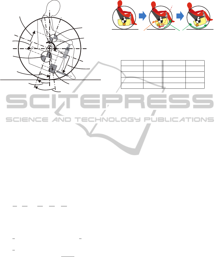
4.1 Modeling Behavior of Vehicle Body
The illustration about the vehicle body behavior is
shown in Figure 6. In Figure 6, m
1
, m
2
and m
3
[kg]
are the masses of the vehicle body, the weight in the
active mass damper system and the passenger, respec-
ICINCO2012-9thInternationalConferenceonInformaticsinControl,AutomationandRobotics
72
[kg]
θ
b[m]
[m]
[m]
[m]
φ
l
m
1
[kg]m
3
τ
θ
[Nm]
d [kg/s]
θ
[kg]m
2
[rad]
[rad]
3
l
1
l
2
Figure 6: Model parameters concerned with vehicle body
behavior.
tively. And, l
1
, l
2
and l
3
[m] show the height of the
gravity centers of the vehicle body, the weight in the
active mass damper system and the passenger, respec-
tively. θ[rad] is the pitch angle between the line con-
necting the gravity center of the vehicle body with the
wheel axis and the vertical axis. φ[rad] is the angle
between the line connecting the gravity center of the
weight with the wheel axis and that connecting the
gravity center of the vehicle body with the wheel axis.
b[m] is the horizontal position of the weight on stand-
ing the vehicle body. τ
θ
[Nm] and d
θ
[kg/s] are the ex-
ternal torque around the wheel axis which is occurred
by driving the wheels and the viscosity damping co-
efficient to rotate the wheels, respectively. Lagrange
equation of motion to the behavior of the vehicle body
is shown as
d
dt
∂T
∂
˙
θ
−
∂T
∂θ
+
∂D
∂
˙
θ
+
∂U
∂θ
= τ
θ
, (1)
where T is the kinetic energy, U is the potential en-
ergy, and D is the dissipative energy. These energies
are represented as
T =
1
2
(m
1
l
2
1
+ m
2
(l
2
2
+ b
2
) + m
3
l
2
3
)
˙
θ
2
+
1
2
m
2
˙
b
2
, (2)
D =
1
2
d
θ
˙
θ
2
, (3)
U = m
1
gl
1
(1− cosθ) + m
2
g
q
l
2
2
+ b
2
·(1− cos(θ− φ)) + m
3
gl
3
cosθ, (4)
where g[m/s
2
] is the gravity acceleration. By substi-
tuting Eqs.(2)-(4)into Eq.(1), the differentialequation
can be obtained as
A
11
¨
θ+ A
12
˙
θ+ A
13
sinθ − m
2
gbcosθ = τ
θ
, (5)
Weight Moving
Gravity Center Moving
Vehicle Body Swaying
Figure 7: Experiment procedure for model parameters iden-
tification.
Table 2: Model parameters.
Notation Values Notation Values
l
1
(m) 0.382 m
1
(kg) 110.30
l
2
(m) 0.380 m
2
(kg) 26.70
l
3
(m) 0.628 m
3
(kg) 60.25
d
θ
(kg/s) 32.325
where
A
11
= m
1
l
2
1
+ m
2
(l
2
2
+ b
2
) + m
3
l
2
3
,
A
12
= 2m
2
b
˙
b+ d
θ
,
A
13
= (m
1
l
1
+ m
2
l
2
− m
3
l
3
)g.
4.2 Identification of Model Parameters
In the model of the behavior of the vehicle body in
previous section, τ
θ
is the external torque such as
the torque generated by the servomotors for driving
wheels. The tilt angle θ and the angular velocity
˙
θ of
the vehicle body and the position b and the velocity
˙
b of the weight are the state variables in the model.
The mass m
1
, m
2
and m
3
, the height l
1
, l
2
and l
3
, and
the viscosity damping coefficient d
θ
are the constant
parameters. The mass m
1
, m
2
and m
3
are measured
by a weigher. The parameters l
1
, l
2
, l
3
and d
θ
are the
unknown parameters, and are identified by minimiz-
ing the error between the vehicle body’s behaviors in
the experiment and the simulation. In the experiment
for the identification, the weight in the active mass
damper system is moved as shown in Figure 7. Then,
the vehicle body is swayed by moving the weight.
The parameters are searched by minimizing the error
using a downhill simplex method, (Nelder and Mead,
1965).
As the result, the identified model parameters are
shown in Table 2. And, the comparison between the
behaviors of the vehicle body in the experiment and
the simulation are shown in Figure 8. (a) and (b) show
the position and the velocity of the weight transfer in
the active mass damper system. (c) and (d) show the
tilt angle and the angular velocity of the vehicle body.
In Figure 8(c) and (d), the solid lines are the experi-
mental results, and the broken lines are the simulation
results. As seen from Figure 8, the sway of the vehi-
cle body can be represented precisely by the proposed
DevelopmentofParallelTwo-wheelVehiclewithLowerGravityCenterofVehicleBody
73

0 2 4 6 8 10 12 14 16 18 20
-0.1
0
0.1
Weight
Position(m)
0 2 4 6 8 10 12 14 16 18 20
-0.1
0
0.1
Weight Transfer
Velocity(m/s)
0 2 4 6 8 10 12 14 16 18 20
-0.2
0
0.2
Angle of
Vehicle Body(rad)
0 2 4 6 8 10 12 14 16 18 20
-0.2
0
0.2
Angular Velocity
of Vehicle Body
(rad/s)
Time(s)
Experiment Simulation
(a)
(b)
(c)
(d)
Figure 8: Comparison between behaviors of vehicle body
in experiment and simulation.
model. The proposed model is used for designing the
sway suppression control system with the active mass
damper system.
4.3 Design of Sway Suppression Control
based on Backstepping Method
For designing the sway suppression control system,
the model of behavior of the vehicle body is simplified
by linearization. It is assumed that the sway angle of
the vehicle body is small. Eq.(5) is linearized as
A
11
¨
θ+ A
12
˙
θ+ A
13
θ− m
2
gb = τ
θ
. (6)
Moreover, Eq.(6) is transformed to the spring-mass-
damper system as
M(b)
¨
θ+C(b,
˙
b)
˙
θ+ Kθ = d(τ
θ
) + u(b), (7)
where
M(b) = m
1
l
2
1
+ m
2
(l
2
2
+ b
2
) + m
3
l
2
3
,
C(b,
˙
b) = 2m
2
b
˙
b+ d
θ
,
K = (m
1
l
1
+ m
2
l
2
− m
3
l
3
)g,
d(τ
θ
) = τ
θ
, u(b) = m
2
gb.
In Eq.(7), τ
θ
is the external torque to sway the ve-
hicle body, and is treated as the disturbance d in the
control system design. b is the weight position, and
the torque m
2
gb generated by the weight position is
treated as the control input u to stabilize the posture
of the vehicle body.
Here, the model in Eq.(7) is a LPV (Linear Param-
eter Varying) system, and has two control variables θ
and
˙
θ. Many control approaches to the LPV system
have been proposed in the previous studies. In this
paper, the backstepping method as one of the control
approaches to the nonlinear system is applied to de-
sign the sway suppression control. It enables to de-
sign easily to the LPV or nonlinear system with small
number of the control variables. The backstepping
method is the control design which a Lyapunov func-
tion is sequentially-constructed with respect to each
state variable based on the formal Lyapunov function
as
U
(x,y)
= V
(x)
+
1
2
y− µ
(x)
2
, (8)
where x is the state variable, y is the controlled vari-
able. In this paper, the state variable x consists of
(θ,
˙
θ), and the controlled variable y is the tilt angle
θ of the vehicle body. At first step, based on Eq.(8),
the candidate Lyapunov function to the state variable
θ in the model is given as
V
1
=
1
2
z
2
1
=
1
2
(y− y
r
)
2
, (9)
where y
r
is the reference tilt angle of the vehicle body.
z
1
is the error between the actual and reference tilt an-
gles. In this paper, the reference y
r
is 0, because the
purpose of the control system is to stabilize the vehi-
cle body on the standing posture. Thus, the Lyapunov
function in Eq.(9) is represented as
V
1
=
1
2
z
2
1
=
1
2
y
2
. (10)
The time derivative of Eq.(10) is shown as
˙
V
1
= z
1
˙z
1
= y˙y. (11)
Here, since ˙z
1
= ˙y =
˙
θ, Eq.(9) is replaced as
˙
V
1
= z
1
˙z
1
= y˙y = y
˙
θ. (12)
By arranging
˙
θ as
˙
θ = −c
1
y,(c
1
≥ 0), (13)
Eq.(12) is represented as
˙
V
1
= − c
1
y
2
≤ 0. (14)
Therefore, it can be obtained as a certain Lyapunov
function. Here, the ideal state variable α to the state
variable
˙
θ is introduced as
α = −c
1
y. (15)
At second step, the error z
2
between the actual
state
˙
θ and the ideal state α is shown as
z
2
=
˙
θ− α. (16)
Based on Eq.(8), the candidate Lyapunov function V
2
involving the state z
2
is given as
V
2
= V
1
+
1
2
z
2
2
. (17)
The time derivative of Eq.(17) is shown as
˙
V
2
=
˙
V
1
+ z
2
˙z
2
. (18)
ICINCO2012-9thInternationalConferenceonInformaticsinControl,AutomationandRobotics
74

Here, by substituting Eqs.(15) and (16) into Eq.(12),
the time derivative of the Lyapunov function
˙
V
1
is rep-
resented as
˙
V
1
= y(z
2
+ α) = y(z
2
− c
1
y) = −c
1
y
2
+ yz
2
. (19)
And, the model shown in Eq.(7) and the time deriva-
tive of the ideal state α in Eq.(15) are substituted into
the time derivative of Eq.(16) as
˙z
2
=
¨
θ−
˙
α =
¨
θ+ c
1
˙y
=
1
M(b)
u(b) − (
C(b,
˙
b)
M(b)
− c
1
)
˙
θ−
K
M(b)
θ, (20)
where the disturbance d is removed from the model of
Eq.(7) for substituting. By substituting Eqs.(19) and
(20) into Eq.(18),
˙
V
2
is represented as
˙
V
2
= − c
1
y
2
+ yz
2
+ z
2
˙z
2
= − c
1
y
2
+ z
2
(˙z
2
+ θ)
= − c
1
y
2
+ z
2
(
1
M(b)
u(b)
−(
C(b,
˙
b)
M(b)
− c
1
)
˙
θ− (
K
M(b)
− 1)θ). (21)
By arranging −c
2
z
2
as
−c
2
z
2
=
1
M(b)
u(b) − (
C(b,
˙
b)
M(b)
− c
1
)
˙
θ
−(
K
M(b)
− 1)θ, (c
2
≥ 0), (22)
˙
V
2
is represented as
˙
V
2
= − c
1
y
2
− c
2
z
2
2
≤ 0. (23)
Therefore, the state variables θ and
˙
θ are in Lyapunov
stability by constructing the Lyapunov function V
2
.
By substituting Eqs.(15) and (16) into Eq.(22), the
control input u is obtained as
u(b) = (C(b,
˙
b) − M(b)(c
1
− c
2
))
˙
θ
+(K − M(b)(1+ c
1
c
2
))θ. (24)
Since u(b) = m
2
gb as shown in Eq.(7), the weight po-
sition b with the state feedback law is derived as
b =
1
m
2
g
{(C(b,
˙
b) − M(b)(c
1
− c
2
))
˙
θ
+(K − M(b)(1+ c
1
c
2
))θ}. (25)
The block diagram of the sway suppression control
system with the active mass damper system designed
by the backstepping method is shown in Figure 9. The
input torque u is calculated using the tilt angle mea-
sured by the tilt sensor and the angular velocity mea-
sured by the gyro sensor. The weight position b is
obtained from the input torque, and is realized by the
weight positioning system in the active mass damper
system. In the feedback control law, b is given from
m g
Disturbance
τ
θ
(Nm)
2
b(m)
+
+
u(Nm)
Behavior of
Vehicle Body
Weight Position
Input Torque
1
Tilt Angle
Angular Velocity
θ
(rad/s)
θ
(rad)
d
dt
2
1
C(b,b) - M(b)(c + c )
.
2
1
K - M(b)(1+c c )
Figure 9: Block diagram of sway suppression control sys-
tem.
the weight position measured by the rotary encoder
fitted on the servomotor in the active mass damper
system.
˙
b is derived as the approximate derivative of
the weight position b measured by the rotary encoder.
In this paper, since it is assumed that the response
of the weight positioning system in the active mass
damper system is much faster than that of the behav-
ior of the vehicle body, the dynamics of the weight
positioning system is not considered.
In this sway suppression control system, the tilt
angle θ and the angular velocity
˙
θ of the vehicle body
are converged fast with increasing the design param-
eters c
1
and c
2
as seen from Eq.(23). However, the
control system with increased design parameters is
influenced by the noise in the signal measured by
the sensors. Moreover, it is hard to track the actual
weight position in the active mass damper system to
the ideal weight position generated by the control law
in the sway suppression control system. In this pa-
per, the design parameters are adjusted by performing
the experiments and the simulations, and obtained as
c
1
= 2.37 and c
2
= 2.37.
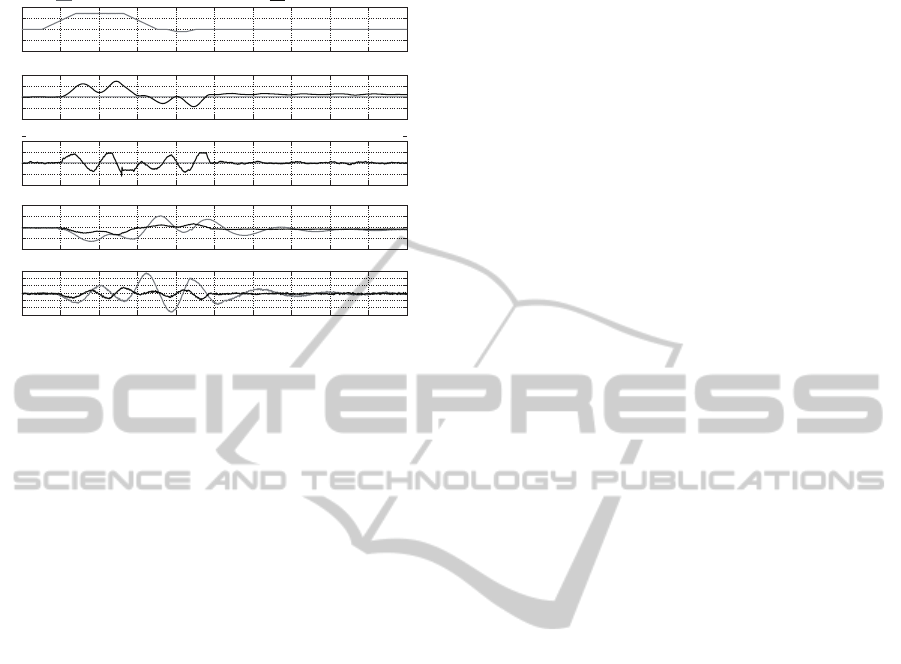
5 EXPERIMENTAL RESULTS
In order to verify the effectiveness of the proposed
sway suppression control system with the active mass
damper system, the experiments using the proposed
parallel two-wheel vehicle are performed. In the ex-
periments, the behavior of the vehicle body with the
sway suppression control system is compared with
that without the sway suppression control system. In
the vehicle without the sway suppression control sys-
tem, the weight in the active mass damper stays at the
center of vehicle body. The experimental results are
shown in Figure 10. In Figure 10, (a) shows the in-
put voltage added to the servomotor for driving the
wheel. (b) and (c) show the position and the veloc-
ity of the weight transfer in the active mass damper,
DevelopmentofParallelTwo-wheelVehiclewithLowerGravityCenterofVehicleBody
75
0 2 4 6 8 10 12 14 16 18 20
-1
-0.5
0
0.5
1
Input Voltage to Motor
for Rotating Wheel(V)
0 2 4 6 8 10 12 14 16 18 20
-0.1
-0.05
0
0.05
0.1
Position of Weight
Transfer(m)
0 2 4 6 8 10 12 14 16 18 20
-0.2
-0.1
0
0.1
0.2
Velocity of Weight
Transfer(m/s)
0 2 4 6 8 10 12 14 16 18 20
-20
-10
0
10
20
Angle of Vehicle
Body(rad)
0 2 4 6 8 10 12 14 16 18 20
-30
-20
-10
0
10
20
30
Angular Velocity of
Vehicle Body(rad/s)
Time(s)
Without Sway Suppression Control (Fixed Weight)
With Sway Suppression Control
x π/180
x π/180
(a)
(b)
(c)
(d)
(e)
Figure 10: Experimental results.
respectively. (d) and (e) show the tilt angle and the
angular velocity of the vehicle body, respectively. In
Figure 10(b)-(e), the black and the gray lines are the
experimental results by the vehicle with and without
the sway suppression control, respectively. As seen
from Figure 10(d), the sway angle of the vehicle body
in the vehicle without the sway suppression control is
over 12.0×π/180(rad). On the other hand, the sway
angle in the vehicle with the sway suppression con-
trol can be suppressed within 7.0×π/180(rad). More-
over, the residual vibration of the sway after driving
the wheel also suppressed by the proposed sway sup-
pression control. Therefore, the proposed sway sup-
pression control is useful to the safety aspect of the
parallel two-wheel vehicle with lower gravity center.
6 CONCLUSIONS
In this paper, the novel parallel two-wheel vehicle
with lower gravity center has been proposed. It has
the advantage of safety than the conventional two-
wheel vehicle with an inverted pendulum structure,
because the proposed vehicle has the stable struc-
ture which the gravity center of the vehicle body is
lower than the wheel axis. And, in order to suppress
sway of the vehicle body while driving the vehicle,
the sway suppression control system with the active
mass damper system is proposed. The control sys-
tem is designed by the backstepping method. By the
experiments using the proposed two-wheel vehicle, it
has been shown that the proposed sway suppression
control system is effective in the sway suppression of
the vehicle body, and useful for the safety aspect to
the proposed two-wheel vehicle.
REFERENCES
C. Nakagawa, K. Nakano, Y. S. and Hirayama, Y. (2011).
Stability of the two-wheeled inverted pendulum vehi-
cle moved by human pedaling. In Journal of System
Design and Dynamics, volume 5, pages 389–402.
Fu, J. and Zao, J. (2007). A new adaptive backstepping
method for nonlinear control of turbine main steam
valve. In Journal of Control Theory and Applications,
volume 5, pages 17–22.
Hun-ok Lim, M. Y. and Tamai, H. (2008). Development of a
portable motor vehicle for personal transportation. In
Proceedings of International Conference on Control,
Automation and Systems 2008, pages 2742–2747.
Karkoub, M. and Parent, M. (2004). Modeling and non-
linear feedback stabilization of a two-wheel vehicle.
In Journal of Systems and Control Engineering, vol-
ume 218, pages 675–686.
M. Sasaki, N. Yanagihara, e. a. (2005). Steering control
of the personal riding-type wheeled mobile platform
(pmp). In Proceedings of IEEE/RSJ International
Conference on Intelligent Robots and Systems, pages
3821–3826.
Nelder, J. and Mead, R. (1965). A simplex method for func-
tion minimization. In Computer Journal, volume 7,
pages 308–313.
Y. Noda, A. K. and Terashima, K. (2010). A mechatronics
vision for smart wheelchairs. In Mobile Robots Navi-
gation, pages 609–628. IN-TECH Book, 1st edition.
Y. Ueno, T. Ohno, K. T. and Kitagawa, H. (2009). The
development of driving system with differential drive
steering system for omni-directional mobile robot.
In Preprints of the IEEE International Conference
on Mechatronics and Automation proceedings 2009,
pages 1089–1094.
ICINCO2012-9thInternationalConferenceonInformaticsinControl,AutomationandRobotics
76
