
Construction and Modeling of a Variable Collective Pitch Coaxial UAV
Jinqiang Cui
1
, Fei Wang
1
, Zhengyin Qian
2
, Ben M. Chen
2
and Tong H. Lee
2
1
NUS Graduate School for Integrative Sciences & Engineering, National University of Singapore, Singapore, Singapore
2
Department of Electrical & Computer Engineering, National University of Singapore, Singapore, Singapore
Keywords:
Coaxial Helicopter, Unmanned Aerial Vehicle, Flapping Dynamics, Model Identification.
Abstract:
This paper describes the construction and modeling of a coaxial unmanned aerial vehicle for in-forest op-
eration. The bare helicopter platform is upgraded and mounted with an onboard navigation system, which
includes central processing units and sensors such as inertial measurement unit, camera and scanning laser
range finder. The model structure of the helicopter is formulated, in which the model of rotor thrust and roll-
pitch dynamics are described in details. The flapping dynamics of the rotor and the stabilizer bar are presented
and lumped into a state-space model. The parameters of the state-space model are identified in frequency
domain using CIFER. Time domain verification with a new set of flight data exhibits excellent agreement with
the prediction of the identified model.
1 INTRODUCTION
With the rapid development of unmanned aerial ve-
hicles (UAVs), a wide range of platforms have been
developed. Model-scale helicopter is one of the more
popular type due to its vertical take-off and landing
capability. A single rotor UAV based on Yamaha R-
50 with a rotor diameter of 3.07 m has been devel-
oped by Carnegie Mellon Univerisity (Mettler et al.,
1999; Mettler, 2002) and the linear UAV models for
hover and cruise flight have been identified. A com-
prehensive nonlinear model for a similar small-scale
single-rotor UAV has been presented by researchers
in National University of Singapore (Cai et al., 2012).
A micro coaxial indoor UAV (muFly) with a rotor di-
ameter of 0.34m has been modeled and identified by
researchers in ETH Z¨urich (Schafroth et al., 2010).
Now muFly is commercially available from Skybotix
(CoaX), which can be an ideal platform for indoor op-
eration and advanced controller design (Fankhauser
et al., 2011).
In our research scope, we intend to develop a UAV
that is capable of flying through the forest. Thus the
platform has to be compact enough to fly among tree
trunks. Compared to single rotor helicopters, coax-
ial helicopters produce better lift efficiency by avoid-
ing power losses from the tangential airflow. What’s
more, coaxial helicopter is also inherently more stable
than single rotor helicopters. Therefore, we choose a
coaxial helicopter as the main frame of our UAV plat-
form.
In this paper, we first describe the mechanical
structure of the coaxial helicopter and the onboard
navigation system in section 2. In section 3, we first
present the model structure of the coaxial helicopter,
then we derive the dual rotor thrust empirically based
on the near-hover flight assumption. The flapping dy-
namics of the rotor and stabilizer bar are presented
separately before they are lumped into a state-space
model. Following this, the lumped system is identi-
fied in frequency domain and verified in time domain.
Section 4 concludes the paper.
2 PLATFORM DEVELOPMENT
2.1 Bare Helicopter
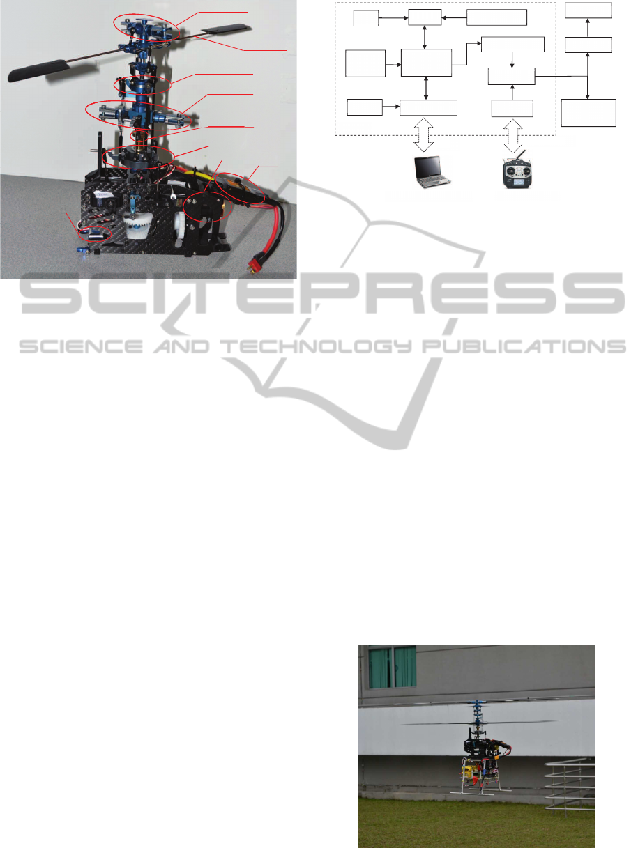
The ‘Kaa-350’ is a coaxial helicopter made in Ger-
many according to the design of full scale coaxial he-
licopter from the Kamov design bureau. This heli-
copter has a rotor diameter of 0.7m and weighs 990g
without battery. Its rotor head is equipped with in-
tegrated hinges and shock resistant dampers. With
the recommended configuration of motor, electronic
speed controller (ESC) and blades, it can fly safely
with a total weight of 2.3 kg. The mechanical struc-
ture of ‘Kaa-350’ is shown in Fig. 1. The rotor blades
are not assembled in order to better illustrate the struc-
286
Cui J., Wang F., Qian Z., Chen B. and Lee T..
Construction and Modeling of a Variable Collective Pitch Coaxial UAV.
DOI: 10.5220/0004039502860291
In Proceedings of the 9th International Conference on Informatics in Control, Automation and Robotics (ICINCO-2012), pages 286-291
ISBN: 978-989-8565-22-8
Copyright
c
2012 SCITEPRESS (Science and Technology Publications, Lda.)
H
G
y
H
eadlock
y
roscope
U
p
To
p
Y
p
per Rotor
p
Swashpla
LowerRo
t
LowerS
w
Moto
S
Y
awContr
te
t
or
w
ashplate
r
S
tabilizer
b
ESC
ol
b
ar
Figure 1: Description of bare helicopter.
ture. The helicopter consists of two contrarotating ro-
tors: the upper rotor and the lower rotor. The pitch an-
gles of the two rotors are controlled by the top swash-
plate and the lower swashplate respectively. The two
swashplates are always parallel to each other since
they are connected by three linkages which rotate with
the top swashplate. The upper rotor is equipped with a
stabilizer bar through a Bell-Hiller mixer which also
influences the cyclic pitch of the upper rotor blade.
The upper rotor and lower rotor are driven by the
same brushless DC electric motor powered by a 3-cell
lithium-polymer battery through the ESC. The rota-
tion speed of the upper rotor and the lower rotor are
thus always the same. Collective and cyclic inputs
from servos are transferred to the lower swashplate
and top swashplate simultaneously, resulting in dy-
namic movement of the helicopter in heave direction
or pitch-roll direction. The yaw direction control is
realized by changing the collective pitch of the lower
rotor.
2.2 Onboard System
The helicopter gains autonomous capability provided
that it is equipped with an onboard navigation sys-
tem. This system consists of various sensors and sig-
nal processing units. As shown in Fig. 2, the avionic
system includes sensors such as inertial measurement
unit (IMU), magnetometer,GPS, scanning laser range
finder and camera. The central processing units are
two gumstix (Overo Fire) units. One gumstix imple-
ments the autonomous control of the helicopter while
the other gumstix is responsible for processing im-
age sequences captured by the camera. Serial com-
Receiver
Control
Gumstix
2.4GHz radio
Vision Gumstix
Multiplexer
Servo Controller
IMU
GPS
Magnetometer
Tail Servo
Ground Control Station
Manual Control
WiFi
Camera
Laser
Scanner
LionHub
Headlock
Three Servos
to swashplate
Figure 2: Avionic System Configuration.
munication is established between the two gumstix
units. The control gumstix also reads the outputs
of onboard sensors and generates autonomous con-
trol signals which are passed to the servo controller
and fed into the multiplexer. The multiplexer has two
4-channel input ports and one 4-channel output port.
Manual control signals from the pilot are transmitted
to the receiver via 2.4GHz radio and fed into the mul-
tiplexer. The outputs of multiplexer are connected to
the three servos controlling the swashplates and the
headlock gyro mixer. The headlock gyro mixer mixes
the yaw control signal and the output of the headlock
gyroscope to generate a composite yaw control signal
that controls the yaw servo. The multiplexer is in-
dispensable since the helicopter may encounter unex-
pected situations during flight where an instant switch
to manual control is required to save the helicopter.
During manual flight or autonomous flight, helicopter
states and sensor outputs are logged online and crit-
ical information are transferred to ground station via
WiFi communication. Control command from ground
station could also be transmitted to the helicopter in
autonomous flight mode. Fig. 3 shows the completed
UAV platform operating in the air.
Figure 3: Helicopter flying in the air.
ConstructionandModelingofaVariableCollectivePitchCoaxialUAV
287
Headlock
controller
Lowerrotor
flappingdynamics
Upperrotor
Fuselage
Lowerrotor
+
6ͲDOF
rigidͲbody
dynamics
ForcesandMoments
F
b
M
b
Kinematics
߶ǡ ߠǡ ߰
V
wind
ݔǡ ݕǡ ݖ
ݑǡ ݒǡ ݓ
mg
ܽ
ௗ௪
ǡ ܾ
ௗ௪
ǡ ݍǡ ݎ
ߜ
ߜ
௧
ߜ
ߜ
ҧ
ௗ
ܽ
௨
ǡ ܾ
௨
ߜ
ௗ
Upperrotor
flappingdynamics
r
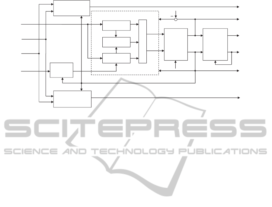
Figure 4: Model Structure Overview.
3 MODELING AND PARAMETER
IDENTIFICATION
3.1 Model Structure
The UAV model structure is shown in Fig. 4. The col-
lective input δ
col
controls the collective pitch angles
of both upper and lower rotors through the two paral-
lel swashplates. The cyclic inputs δ
lat
and δ
lon
tilt the
upper and lower swashplates and generate flapping
motion for both rotors, causing the longitudinal and
lateral movements of the helicopter. The yaw chan-
nel control δ
ped
is first mixed with the output of the
headlock gyro (PI controller) before it is applied on
the collective pitch of the lower rotor. The model is
denoted in a compact form as follows,
˙
x = f(x,u,w) , (1)
where
x = (
x y z u v w φ θ ψ· ··
·· · p q r a
up
b
up
a
dw
b
dw
r
f
)
T
,
u = (
δ
lat
δ
lon
δ
col
δ
ped
)
T
,
w = (
ω
u
ω
v
ω
w
)
T
.
x is the state vector, u is the input vector, δ
col
, δ
lat
,
δ
lon
and δ
ped
are the collective, lateral, longitudinal
and pedal inputs to the whole system. w
w
stands for
the wind disturbance velocity. The overall dynamics
of the helicopter could be separated into three sub-
systems: the roll-pitch dynamics, the yaw dynamics
and the heave dynamics. The roll-pitch dynamics,
capturing the angular responses of helicopter to the
cyclic inputs, constitutes the core of helicopter dy-
namics (Mettler et al., 1999). Thus we mainly present
our results in the modeling and identification of the
roll-pitch dynamics in this paper.
3.2 Thrust Formulation
It is a very complex issue to address the coaxial rotor
aerodynamics. A comprehensive survey (Coleman,
1997) has covered the major aerodynamic experi-
ments and computational models dealing with coax-
ial rotor systems. It covered issues of separation dis-
tance, load sharing between rotors, wake structure,
solidity effects, swirl recovery, and the effects of hav-
ing no tail rotor. (Lim et al., 2009) investigated the
ground and rotor spacing effects and Reynolds num-
ber scaling effect by comparing three rotor configu-
rations, concluding that the coaxial rotor spacing ef-
fect on hover performance was minimal for the rotor
spacing larger than 20% of the rotor diameter. Re-
searchers (Kim and Brown, 2008; Kim and Brown,
2006) at Glasgow University has developed a Vor-
ticity Transport Model (VTM) to study the aerody-
namics of coaxial rotor systems. They stated that the
state-of-the-art computational modeling of helicopter
aerodynamics had managed to model the interactive
aerodynamic flow field associated with a coaxial ro-
tor system.
Since the designed UAV will work at near-hover
condition, we decide to first extract an empirical rela-
tionship between dual rotor thrust T
mr
and collective
input δ
col
. A test bench is utilized to facilitate a series
of tests where the dual rotor thrust and collectiveinput
are recorded simultaneously. Fig. 5 shows the results
of five tests performed on two fully charged batteries.
After fitting the results using the least square method
and averaging the five groups of coefficients, a linear
ICINCO2012-9thInternationalConferenceonInformaticsinControl,AutomationandRobotics
288

−0.25 −0.2 −0.15 −0.1 −0.05 0 0.05
17.5
18
18.5
19
19.5
20
20.5
21
δ
col
(−1,1)
Force(N)
Dual Rotor Force vs Collective Input
Test 1 with battery 1
Test 2 with battery 1
Test 1 with battery 2
Test 2 with battery 2
Test 3 with battery 2
Figure 5: Thrust of dual rotor against collective input.
relationship is obtained as:
T
mr
= K
t
δ
col
+ T
0
, (2)
where K
t
= 10.09N and T
0
= 20.812N.
For near-hover flight, the direction of the rotor
thrust can be assumed to remain perpendicular to the
rotor tip-path-plane. The projections of main rotor
thrust on the helicopter body axes are defined as:
X
mr
= −T
mr
sina
s
, (3)
Y
mr
= T
mr
sinb
s
, (4)
Z
mr
= −T
mr
cosa
s
cosb
s
. (5)
The moments generated by the main rotor are:
L
mr
= (K
β
+ T
mr
H
mr
) sin(b
s
), (6)
M
mr
= (K
β
+ T
mr
H
mr
) sin(a
s
), (7)
where K
β
is the spring constant, H
mr
is the distance
from center of gravity (CG) to the middle of two ro-
tor planes, a
s
and b
s
are the equivalent longitudinal
and lateral flapping angles respectively. The torques
from upper rotor and lower rotor are balanced when
no heading change is required.
3.3 Flapping Dynamics
3.3.1 Bare Rotor Flapping Dynamics
One way to represent the rotor dynamics is to regard
it as a rigid disc which can tilt about the longitudi-
nal and lateral axes. Detail description of the rotor
equations are extremely complicated. Here, a sim-
plified formulation is adopted, where the rotor forces
and moments are expressed as a polynomial function
of the rotor state variables (Mettler, 2002). Moreover,
by removing the higher order terms of the Tip-Path-
Plane (TPP) equation, the remaining first-order rotor
dynamics could be expressed as:
τ
r
˙
b
i
= −b
i
− τ
r
p+ B
a
a
i
+ θ
cyc,bi
, (8)
τ
r
˙a
i
= −a
i
− τ
r
q+ A
b
b
i
+ θ
cyc,ai
, (9)
where
A
b
= −B
a
=
8K
β
γ
dw
Ω
2
mr
I
β,mr
, (10)
τ
r
=
16
γ
r
Ω
mr
1−
8e
mr
3R
mr
−1
, (11)
γ
r
=
ρc
mr
C
lα,mr
R
4
mr
I
β,mr
. (12)
a
i
and b
i
(i represents { up, dw}) are the first-order
TPP flapping angles in the longitudinal and lateral
directions for upper and lower rotors. τ
r
and γ
r
are
the flapping time constant and the lock number of the
rotor blades respectively, I
β,mr
is the blade moment
of inertia. θ
cyc,a
and θ
cyc,b
are the longitudinal and
lateral cyclic pitch of rotor blade. The approximate
formulation in Eq.(8-9) characterizes the crucial TPP
responses with respect to cyclic control inputs and he-
licopter motion.
3.3.2 Stabilizer Bar Flapping Dynamics
The stabilizer bar, which is attached to the upper main
rotor shaft via a free-teetering hinge, can be regarded
as a secondary rotor. It consists of two paddles and
a steel rod. The stabilizer bar is not designed to pro-
duce thrust or moment on the main hub, whereas its
main function is to adjust the helicopter dynamics via
the Bell-Hiller mixer by augmenting the cyclic pitch
command of the upper rotor. It serves as a feed-
back system which increases the helicopter robustness
against wind gust and turbulence (Cai et al., 2011).
The flapping dynamics of stabilizer bar can be ex-
pressed as two first-order differential equations:
˙c
s
= −q −
1
τ
sb
c
s
+
C
lon
τ
sb
δ
lon
, (13)
˙
d
s
= −p−
1
τ
sb
d
s
+
D
lat
τ
sb
δ
lat
, (14)
where τ
sb
is the stabilizer bar flapping time constant,
and it can be calculated as
τ
sb
=
16
γ
sb
Ω
mr
, (15)
where γ
sb
is the stabilizer bar Lock number:
γ
sb
=
ρc
sb
C
lα,sb
R
4
sb
− r
4
sb
I
β,sb
. (16)
ConstructionandModelingofaVariableCollectivePitchCoaxialUAV
289
The free-teetering hinge does not constrain the flap-
ping of stabilizer bar, thus there is no coupling be-
tween the longitudinal and lateral flapping motions.
The augmented rotor cyclic pitch of upper rotor can
be expressed as
θ
cyc,aup
= A
lon
δ
lon
+ K
sb
c
s
, (17)
θ
cyc,bup
= B
lat
δ
lat
+ K
sb
d
s
, (18)
where K
sb
is the ratio of rotor blade cyclic pitch to
stabilizer bar flapping.
3.3.3 Lumped Flapping Dynamics
In this coaxial helicopter configuration, the upper ro-
tor and the lower rotor receive the same cyclic input
(δ
lon
,δ
lat
) since the top swashplate and bottom swash-
plate are always parallel. To minimize the overall
complexity of the model, the two counter rotating ro-
tor discs are treated as one equivalent rotor disc with
respect to flapping motions. Thus there exists only
two equivalent flapping angles (a
s
, b
s
). This assump-
tion produces accurate results which are shown in sec-
tion 3.3.4. Combining Eq. 8-18, the lumped flapping
dynamics subsystem could be represented in the fol-
lowing state space model:
˙
x = A x+ B u, (19)
˙
y = C x, (20)
where
A =
0 0 0 L
b
0 0 M
a
0
0 −1 −
1
τ
A
b
τ
−1 0
B
a
τ
−
1
τ
, (21)
B =
0 0
0 0
0 A
′
lon
B
′
lat
0
, (22)
C =
1 0 0 0
0 1 0 0
, (23)
x =
p
q
a
s
b
s
, u =
δ
lat
(t − τ
lat
)
δ
lon
(t − τ
lon
)
, y =
p
q
, (24)
L
b
=
mgH
mr
+ K
β
J
xx
, M
a
=
mgH
mr
+ K
β
J
yy
. (25)
The rotor spring constant K
β
, the lateral and longi-
tudinal control derivatives B
′
lat
, A
′
lon
, the lateral and
longitudinal control delay τ
lat
, τ
lon
, and the equiva-
lent flapping time constant τ are to be identified via
frequency domain identification in section 3.3.4. The
coupling term A
b
and B
a
are neglected.
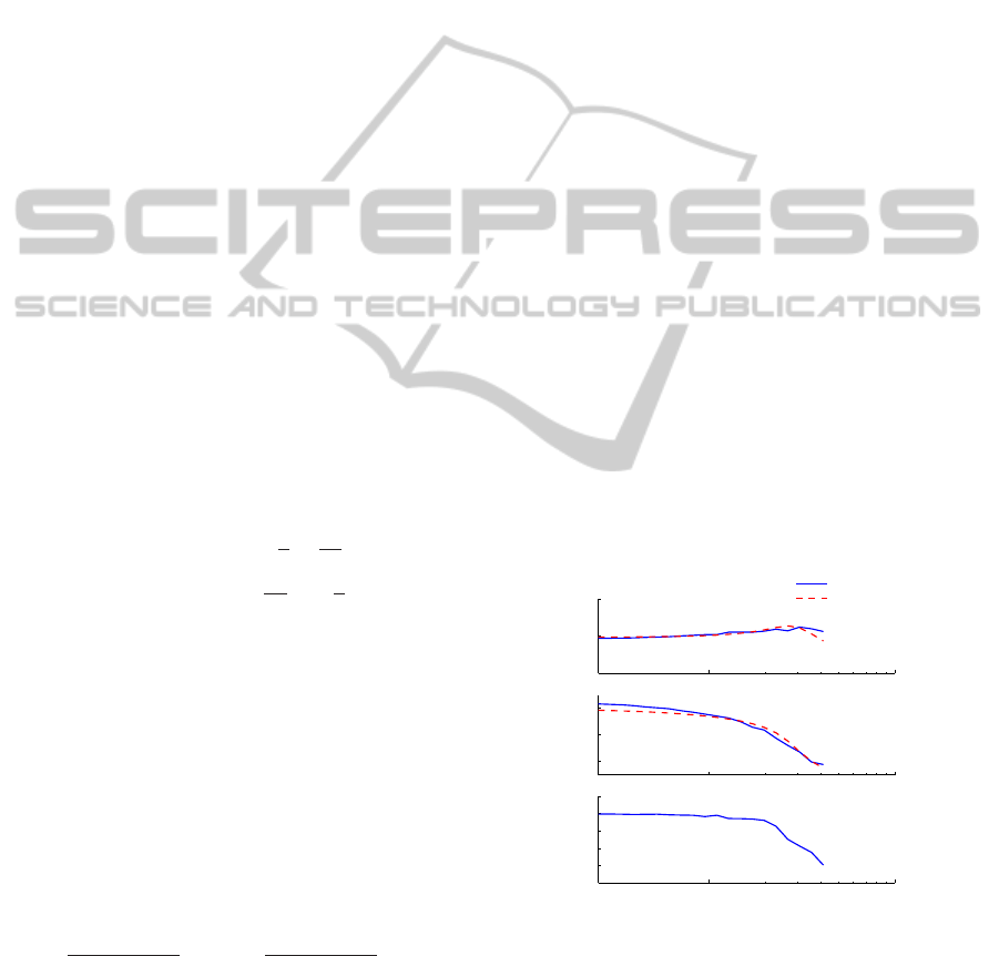
3.3.4 Roll-Pitch Dynamics Identification
The flapping dynamics identification makes full use
of a toolkit called CIFER developed by the U.S.
Army and NASA specifically for rotorcraft applica-
tions (Mettler et al., 1999). It incorporates a range of
utilities to support the various steps of the identifica-
tion process. Flight tests featuring frequency-sweep
input in the longitudinal and lateral directions are per-
formed multiple times. During the flights, the control
inputs and the helicopter angular rates are recorded
online with a sampling rate of 50Hz. CIFER identi-
fies the model parameters by searching for the best-
fit parameters to match frequency responses between
the flight test data and the hypothetic model. Fig. 6
shows the on-axis pitch angular rate response with re-
spect to longitudinal input. The coherence level re-
mains above 0.6 up to 30 rad/s. This good coherence
indicates the good linearity of the helicopter in hover
flight (Tischler and Remple, 2006). Time domain ver-
ification is also performed with another flight test data
which is not used in the identification process. Fig.7
shows excellent agreement between the model simu-
lation and the flight data in both longitudinal direc-
tion. The same process is applied to the lateral direc-
tion where the roll dynamics is identified in frequency
domain and verified in time domain. Table. 1 lists the
values of the identified parameters together with their
Cramer-Rao percent and insensitivity. The Cramer-
Rao percent and insensitivity are less than 15% and
5% respectively, indicating the high accuracy of the
identified parameter.
10
1
10
2
−20
0
20
Magnitude (DB)
δ
lon
−− q
Experiment
Simulation
10
1
10
2
−200
−100
0
Phase (deg)
10
1
10
2
0.2
0.4
0.6
0.8
1
1.2
Coherence
Frequency(Rad/Sec)
Figure 6: Comparison of frequency response from longitu-
dinal input to pitch angular rate.
4 CONCLUSIONS AND FUTURE
WORK
In this paper we have presented our current progress
ICINCO2012-9thInternationalConferenceonInformaticsinControl,AutomationandRobotics
290
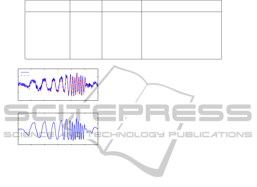
Table 1: Parameters identified from CIFER.
Parameter
Cramer-Rao
Insensitivity(%) Physical meaning
Percent(%)
L
b
= 675.8s
−2
7.171 2.433 Lateral rotor spring derivative
M
a
= 794.7s
−2
7.525 2.589 Longitudinal rotor spring derivative
τ = 0.068s 9.301 3.537 Equivalent flapping time constant
A
′
lon
= 0.898rad/s 4.152 1.962 Longitudinal control derivative
B
′
lat
= 1.069rad/s 4.157 1.935 Lateral control derivative
τ
lat
= 0.03355s 12.08 4.477 Lateral control delay
τ
lon
= 0.03390s 12.17 4.440 Longitudinal control delay
K
β
= 11.5029Nm NA NA Rotor spring constant
0 2 4 6 8 10 12
−2
−1
0
1
2
q (rad/s)
Experiment
Simulation
0 2 4 6 8 10 12
−1.5
−1
−0.5
0
0.5
1
1.5
Time(s)
δ
lon
Figure 7: Time domain verification of longitudinal input to
pitch angular rate.
regarding the development and modeling of a coaxial
UAV platform. For platform construction, the payload
capability of the bare coaxial helicopter is guaranteed
by careful selection of the key components such as
motor, blade and ESC. The onboard avionic system
is designed and assembled onto the helicopter frame
using mechanical dampers. For modeling of the heli-
copter, the model structure of the platform has been
laid out. The coaxial rotor thrust has been empir-
ically derived. More importantly, the roll-pitch dy-
namics of the helicopter are formulated. Through fre-
quency domain identification in CIFER, the equiva-
lent flapping time constant and spring constant are
fine-tuned. Time domain verification using a new set
of test data has validated the fidelity of the identi-
fied roll-pitch dynamics. Future research work will
focus on the modeling of heave dynamics and yaw
dynamics which will produce a complete model. Ad-
ditional effort will be made to study the coaxial rotor
wake structure so that an optimal coaxial configura-
tion could be achieved.
ACKNOWLEDGEMENTS
The authors would like to thank Dr. Feng Lin and Dr.
Guowei Cai from NUS Temasek Laboratories for the
constructive discussion and genuine help. We would
also like to thank ‘Temasek Defence Systems Insti-
tute’ for funding the project.
REFERENCES
Cai, G., Chen, B. M., and Lee, T. H. (2011). Unmanned
Rotorcraft Systems. Springer, London.
Cai, G., Chen, B. M., Lee, T. H., and Lum, K.-Y. (2012).
Comprehensive nonlinear modeling of a miniature un-
manned helicopter. Journal of the American Heli-
copter Society, 57(1):1–13.
Coleman, C. P. (1997). A survey of theoretical and experi-
mental coaxial rotor aerodynamic research. Technical
report, NASA Ames Research Center.
Fankhauser, P., Bouabdallah, S., Leutenegger, S., and Sieg-
wart, R. (2011). Modeling and decoupling control of
the coax micro helicopter. In Proc. of the IEEE/RSJ
International Conference on Intelligent Robots and
Systems (IROS).
Kim, H. and Brown, R. (2006). Coaxial rotor performance
and wake dynamics in steady and manoeuvring flight.
In American Helicopter Society 62nd Annual Forum
Proceedings, volume 62, page 20.
Kim, H. and Brown, R. (2008). Modelling the aerodynam-
ics of coaxial helicopters–from an isolated rotor to a
complete aircraft. In Proceedings of the EU-Korea
Conference on Science and Technology, pages 45–59.
Lim, J. W., McAlister, K. W., and Johnson, W. (2009).
Hover performance correlation for full-scale and
model-scale coaxial rotors. Journal of the American
Helicopter Society.
Mettler, B. (2002). Identification Modeling and Charac-
teristics of Miniature Rotorcraft. Kluwer Academic
Publisher, Nowell, MA.
Mettler, B., Tischler, M. B., and Kanade, T. (1999). System
identification of small-size unmanned helicopter dy-
namics. In American Helicopter Society 55th Annual
Forum Proceedings, volume 2, pages 1706–1717.
Schafroth, D., Bermes, C., Bouabdallah, S., and Siegwart,
R. (2010). Modeling and system identification of
the mufly micro helicopter. Journal of intelligent &
robotic systems, 57(1):27–47.
Tischler, M. and Remple, R. (2006). Aircraft and rotor-
craft system identification: Engineering Methods with
Flight Test Examples. AIAA.
ConstructionandModelingofaVariableCollectivePitchCoaxialUAV
291
