
Optimized Chipping Processes with a New Mechatronic Tool System
Application of Strain Gauge Sensors and Piezoelectric Actuators
Franz Haas
1
, Elke Nuspl
2
and Manfred Pauritsch
1
1
Department of Automation Technology, FH CAMPUS 02, Körblergasse 126, A-8010 Graz, Austria
2
TCM International Tool Consulting & Management GmbH, Technologiepark 3, A-8510 Stainz, Austria
Keywords: Chipping Technology, Mechatronic Tool System, Condition Monitoring, Piezoelectric Actuators.
Abstract: The paper introduces a new measurement device which allows collecting the chipping force in three
directions and additionally the process temperature. The apparatus consists of a specially designed tool
holder with integrated strain gauges, the electronic measuring equipment and the evaluation software.
During the first period a new device for research and development purposes has been designed, experiments
on innovative materials are presented including the comparison with simulation results. The next step of the
project incorporates the product development based on the previous experience with targets accuracy, cost
effectiveness, reliability and the possibility of active damping of tool vibrations. To achieve the last
mentioned demand a piezoelectric actuator is integrated into the tool shank and works against the vibration
forces.
1 INTRODUCTION
Chipping technologies (e.g. turning, milling or
grinding) are still of high importance in the field of
industrial production. For instance both combustion
engine and electrically driven automobiles need
many parts that have to be produced or finished by
chipping processes because of accuracy and cost
effectiveness. Some of the current developments in
this field are listed below:
Increasing number of parts made of innovative
materials (e.g. titanium, composites) for
lightweight constructions;
High temperatures caused by hard machining
and dry processing;
General demand of optimized cutting
parameters and less vibration;
Hybrid machine tools characterized by
integration of several techniques (e.g. turning
and laser heat treatment or milling and friction
stir welding).
Therefore the demand to integrate mechatronics
into the tool holders is evident. Preconditions are the
robust and simple sensor and/or actuator application
at acceptable prices.
2 STATE OF THE ART
This chapter gives a summary of useful basics in the
area of test methods and represents an overview of
new cutting tools and cutting materials.
Concerning the measurement of cutting forces
two different principles can be divided. Most of the
laboratory devices use a dynamometer based on the
piezoelectric effect. The sensor delivers electric
charges that are transported to a charge amplifier
through an insulated cable. The amplifier converts
the charges into an output voltage (Kistler, 2009).
As standard a special platform with four sensors is
used to enable a multi-component measurement of
forces and torques. In the case of chipping the
orthogonal components F
x
, F
y
, F
z
and the drive
torque M
z
at the main spindle are of special interest.
Turning as a process with a rotating workpiece
and tool inserts of defined geometry represents the
typical example to measure the orthogonal process
force components.
Strain gauge and piezoelectric force
measurement devices are presented in (Audy, 2006)
with a detailed discussion and classification of the
error sources. It is pointed out that a two-component
metal machining dynamometer equipped with strain
gauges doesn´t have satisfying long term stability
without any compensation because of temperature
614
Haas F., Nuspl E. and Pauritsch M..
Optimized Chipping Processes with a New Mechatronic Tool System - Application of Strain Gauge Sensors and Piezoelectric Actuators.
DOI: 10.5220/0004044006140617
In Proceedings of the 9th International Conference on Informatics in Control, Automation and Robotics (ICINCO-2012), pages 614-617
ISBN: 978-989-8565-21-1
Copyright
c
2012 SCITEPRESS (Science and Technology Publications, Lda.)
effects on the strain gauges.
A small three-component dynamometer with
circular holes is described in (Tani, 1983). The
linearity of output is excellent without hysteresis.
The calibration of all three directions can be carried
out with low interaction between measurement
directions.
3 LABORATORY DEVICE
3.1 Mechanics and Sensors
The mechatronic tool is constructed similar to a
standard tool holder consisting of a shank and the
cutting part with the carbide metal inserts. In
comparison with standard tool holders the fixation of
modules with different insert geometries is enabled.
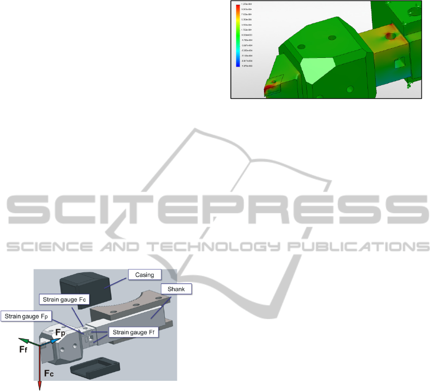
The basic measurement principle is very simple
and can also be utilized in low cost products (Haas,
2011). The tool shank has the function of a beam in
bending as the result of cutting and feed force
components (see Fig. 1).
Figure 1: Dynamometer with strain gauges.
The very small deflections cause output signals
of each bridge circuit with four strain gauges to
compensate for temperature effects. Concerning the
third axis the deformation near a rectangular hole is
picked up by additional strain gauges, but the signal
is small in relation to the others and calibration is
much more difficult.
The FEM analysis (Fig. 2) of the mechatronic
tool is helpful to estimate the strain values at the
virtual model to select the suitable strain gauge
types.
Another benefit of simulation is the optimization
of stiffness to ensure that distortion und stresses are
below the limits.
The force components F
c
, F
f
and F
p
can be
calculated according to the equations (1) to (3). The
specific force values (kc1.1, kf1.1, kp1.1) are
Figure 2: X-component of strain (F
c
= 1200 N).
multiplied with the width (b) and thickness (h) of the
chips. The exponent (m
c-1) considers the decreasing
amount of the specific forces with higher values of
(h) in the case of cutting force.
F
c
= k
c1.1
b h
()
(1)
F
f
= k
f1.1
b h
(
)
(2)
F
p
= k
p
1.1
b h
()
(3)
To complete the test equipment it is necessary to
measure the temperature at the deformation zone
simultaneously. In this case a dynamic test shows
the direct consequence of tool wear with regard to
the process forces and to the thermal load that tool
insert and work piece have to withstand. Especially
thin and lightweight parts are sensitive to higher
temperatures, distortion and failure costs may be the
results. Dry processing and hard machining accept
higher temperatures to reduce the costs for cooling
lubricants and to avoid environmental pollution.
These machining strategies require thermal test
results to detect the speed limits.
Therefore an infrared temperature sensor with a
range of 200°C to 1000°C is integrated into the
measuring and evaluation concept. The temperature
level is able to be influenced by location and
intensity of heat sources, the heat conductance value,
the dimensions of heat dissipation parts, time
interval of direct contact and at last external cooling.
3.2 Electronics
The interface electronics fulfils functions that
exceed commercially available equipment. Four
voltage signals can be processed as a multichannel
measurement, three bridge circuit values from the
dynamometer and the temperature sensor output.
The main item on the printed board (see Fig. 3)
is the analogue digital converter with a sampling rate
of 70 kHz and a resolution of 24 bit.
In relation to commonly used boards for strain gauge
bridges the new design enables the highly dynamic
digitalization of the analogue signals.
As electronic protective method a high frequency
OptimizedChippingProcesseswithaNewMechatronicToolSystem-ApplicationofStrainGaugeSensorsand
PiezoelectricActuators
615

Figure 3: Interface electronics, PCB-layout.
noise filter and an over-voltage protection are
integrated per channel. The measuring board
consists of a USB connector to communicate with
the PC. By default the communication is done by a
WLAN module with 2.4 GHz transmission
frequency, therefore it is also possible to access the
device worldwide per internet. This feature ensures a
high reliability of the remote data transfer even
under rough conditions on the factory floor. In
addition an external analysis or remote maintenance
is possible.
In the case of turning operation tests can also be
triggered by indication at the main spindle. A
microcontroller is responsible for internal
measurement control and communication.
Configuration and status information are displayed
on a small screen.
3.3 Calibration and Errors
During calibration exactly weighted loads are
applied to the dynamometer. As consequence each
mass causes deformation and defined output
voltages at the bridge circuits. One calibration curve
per direction must be calculated as a result of output
voltages, the applied masses and calibration setup
dimensions. Possible device errors are caused by
long term and temperature drift, nonlinearity of
strain gauge signals. As basic requirements of
measurement calibration has been finished and
comparisons with other systems and with calculated
force results has been done
4 MEASUREMENT RESULTS
The new device offers benefits for a lot of
applications, for example research and development
as well as large-scale production or education. The
independent comparison between measuring results
and chipping process simulation illustrates a
sufficient compliance.
4.1 Turning Process
First straight turning measurements are presented.
To achieve reliable results system calibration should
be performed before data collection.
Figure 4 shows force values and the process
temperature for hardened steel machining, which
becomes more and more important for economic and
sustainable production. In this case the dominant
factors are heat production, thermal resistance of
inserts and efficient cooling.
As a result of cutting depth, cutting speed and
feed velocity, the temperature rises up to about
260°C as a constant condition (see Fig. 4 at the right
axis).
Figure 4: Straight turning of hardened steel (F
c
,
F
f,.
T).
The following diagram (Fig. 5) introduces results
of stainless steel machining.
Figure 5: Straight turning of stainless steel.
One of the promising materials of lightweight
constructions is titanium, but it is difficult to be
machined with chipping processes. Figure 6 shows
the increase of the measurement values after the tool
starts with machining. The alternating temperature
profile is caused by discontinuous chip formation.
ICINCO2012-9thInternationalConferenceonInformaticsinControl,AutomationandRobotics
616
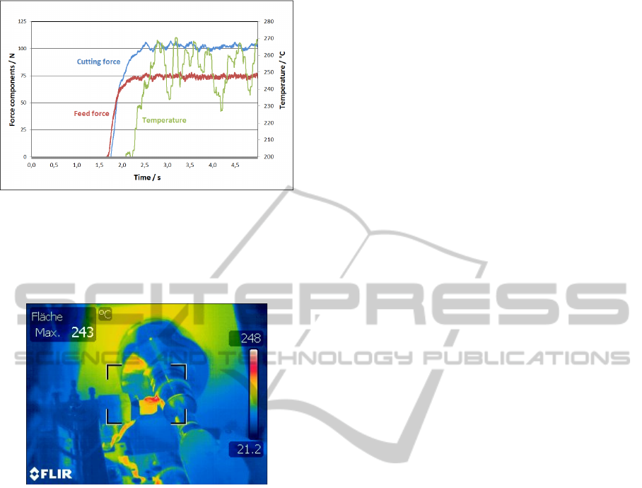
Figure 6: Cutting force, feed force and temperature,
straight turning of titanium alloy with carbide inserts.
Infrared camera pictures and videos have been
shot to validate the temperature results and to get an
impression of the whole thermal field (Fig. 7).
Figure 7: Infrared picture of titanium machining.
It should be pointed out that satisfying
correlation between the thermal radiation result (see
Fig. 6) and the infrared method could be achieved
(maximum temperature of about 250°C).
4.2 Simulation
Optimization of chipping processes based on
measurements should be extended to simulation. The
target of this project (Blaha, 2010) is the FEM
simulation of turning operations for three materials
(C45, X2CrNiMo17-13-2 and Ti6Al4V).
As the most important simulation assessment criteria
cutting forces have to be analysed and compared
with measurements mentioned above.
The required tribologically parameters have to be
determined by special tests (Horwatitsch, 2007). The
comparison of measurement versus simulation has
shown a satisfying compliance in the case of
numerical integration of the local cutting forces
along the comma-shaped chip (Blaha, 2010).
Depending on the material the deviation varies
between 2 and 12 percent considering the cutting
force results.
5 CONCLUSIONS
The triangle relationship between workpiece, cutting
tool and machine tool finally determines the
economic production and always requires new
solutions for each particular case, which can only be
found as a result of chipping tests and process
monitoring.
The paper presents a measuring device for
laboratory purposes as well as a mechatronic tool for
industrial production. The idea of the laboratory
device is to pick up all necessary process data for
optimization purposes. In the case of the
mechatronic product low cost and robust design are
of higher importance. This principle is not limited to
specific manufacturing techniques, it is generally
applicable and represents a significant module to
fulfil the targets of intelligent production.
REFERENCES
Audy J., 2006. An appraisal of techniques and equipment
for cutting force measurement, In Journal of Zhejiang
University, p. 1781-1789.
Blaha, J., Horwatitsch, D., (et al.), (2010). Endbericht
F&E Headquarter Strategy, TCM International Tool
Consulting & Management GmbH, p. 7-28.
Haas, F., Nuspl, E., 2011. Präzises, schnelles Messgerät
für mobiles Condition Monitoring von Zerspa
nungsprozessen, In AALE 2011, p. 161-169.
Horwatitsch, D. (et al.), (2007). Ermittlung der Reibung
zur Verwendung in einer FE-basierten Prozess-
simulation eines Zerspanungsprozesses, In
Proceedings ÖTG Symposium 2007, p. 45-52.
Kistler (Ed.), 2009. Präzise Messsysteme für die
spanabhebende Fertigung, p. 7-9.
Tani, Y., Hatamura, Y., Nagao, T., (1983). Development
of Small Three-component Dynamometer for Cutting
Force Measurement, p. 657-658.
OptimizedChippingProcesseswithaNewMechatronicToolSystem-ApplicationofStrainGaugeSensorsand
PiezoelectricActuators
617
