
From Robot Commands to Real-time Robot Control
Transforming High-level Robot Commands into Real-time Dataflow Graphs
Andreas Schierl, Andreas Angerer, Alwin Hoffmann, Michael Vistein and Wolfgang Reif
Institute for Software and Systems Engineering, University of Augsburg, D-86135 Augsburg, Germany
Keywords:
Industrial Robotics, Robot Programming, Real-time Robot Control.
Abstract:
Task descriptions in robotics always provide a level of abstraction in order to simplify the use of robots. Nev-
ertheless, aspects such as execution time determinism and closed-loop control are still essential for industrial-
strength robotics systems. For this reason, we propose an approach to combine high-level task description with
real-time robot control. At application runtime, coordinated and sensor-guided robot actions are composed us-
ing an object-oriented application programming interface. The resulting high-level command descriptions are
then automatically transformed into dataflow graphs and executed with real-time guarantees on robot hard-
ware. The approach is illustrated with several examples.
1 INTRODUCTION
When programming robots to perform long or com-
plex tasks, the programmer usually wants to abstract
from the technical details of controlling the robot
hardware, e.g. hard real-time constraints, closed-
loop controllers, or controller parameters. The focus
should rather lie on the what aspect of the task (Pires,
2009). For this reason, manufacturers of industrial
robots provide proprietary robot programming lan-
guages that are usually mainly sequential and allow
the specification of a fixed set of motions and simple
tool actions. In the research community, task descrip-
tions use different formalisms such as petri nets (Pe-
terson, 1981), a task description language (Simmons
and Apfelbaum, 1998) or constraints (Smits et al.,
2008), and are covered in various robotics frame-
works, however with certain drawbacks.
In the research project SoftRobot, an extensible
software architecture (Hoffmann et al., 2009) has
been developed to both facilitate the development of
robotic applications and keep real-time constraints in
mind. This multi-layer architecture (cf. Fig. 1) allows
to program industrial robots using a standard, high-
level programming language (e.g. Java) and, at the
same time, ensures that commands are executed on
the robot hardware with real-time guarantees.
The lowest layer is the Robot Control Core (RCC)
which is responsible for controlling the robotic hard-
ware and, thus, must be running on a real-time oper-
ating system. It is interfaced by and executes tasks
described in a data-flow language called Realtime
Robot Control Core
Realtime Primitives Interface
Implementation
Application Application
Robotics API
Robot Hardware
Automated transformation
into real-time dataflow graphs
Real-Time
Robot Control
Application
Programming
Figure 1: Robot application are programmed against the
Robotics API. High-level commands specified using the
Robotics API are automatically transformed into dataflow
graphs at runtime and exectued with real-time guarantees.
Primitives Interface (RPI) (Vistein et al., 2010). The
dataflow language consists of (robotics-specific) cal-
culation blocks which are referred to as (real-time)
primitives and are connected by data-flow links to
form a graph, referred to as primitive net. During
execution of a primitive net, each primitive is evalu-
ated in each calculation cycle. The primitives have
known worst-case time complexity and thus allow
the execution of the task in a deterministic manner.
The calculation scheme and semantics are similar to
LUSTRE (Caspi et al., 1987) used in the commercial
SCADE Suite
1
for safety-critical embedded software.
1
http://www.esterel-technologies.com/products/scade-suite/
150
Schierl A., Angerer A., Hoffmann A., Vistein M. and Reif W..
From Robot Commands to Real-time Robot Control - Transforming High-level Robot Commands into Real-time Dataflow Graphs.
DOI: 10.5220/0004046301500158
In Proceedings of the 9th International Conference on Informatics in Control, Automation and Robotics (ICINCO-2012), pages 150-158
ISBN: 978-989-8565-22-8
Copyright
c
2012 SCITEPRESS (Science and Technology Publications, Lda.)

A reference implementation of an RPI-compatible
RCC (Vistein et al., 2010) was developed using ORO-
COS (Bruyninckx, 2001) and Linux with Xenomai
real-time extensions.
The ControlShell (Schneider et al., 1998) frame-
work employs an approach similar to RPI regarding
the dataflow structure of programs. Considering the
overall architecture, ControlShell however focuses on
manual programming of these dataflow programs, in
combination with a state machine extension, and pro-
vides a toolchain for that purpose. In contrast, the RPI
layer in the SoftRobot architecture is intended to pro-
vide a set of fine-grained, reusable and combinable
primitives. Primitive nets are intended to be gener-
ated by a higher level program rather than created by
hand. The fact that the primitive nets are interpreted
by the RCC rather than compiled to a target platform
distinguishes the architecture from many other frame-
works like ORCCAD (Borrelly et al., 1998) or Mis-
sionLab (MacKenzie et al., 1997). The interpretation
approach allows to modify high level commands in
the application depending on the current situation.
On top of RPI, a Java implementation is providing
the Robotics API (Angerer et al., 2010), an object-
oriented, extensible application programming inter-
face for robot applications. The Robotics API con-
tains an open domain model of (industrial) robotics
describing the available actuators and devices, as well
as possible actions and tasks, and also includes ways
of maintaining a world model of the relevant parts of
the environment. The Robotics API allows to specify
actions to be executed by actuators, which are then
transformed into a graph of (real-time) primitives, and
executed on the Robot Control Core.
To describe more complex tasks where multiple
actions have to be executed with given timing re-
quirements and real-time guarantees, multiple com-
mands are combined into real-time transactions. Such
transactions are composed and configured using the
Robotics API, and are then automatically converted
into primitive nets. This conversion transforms vari-
ous commands and their defined start and stop con-
ditions into one dataflow graph. This transformation
is vaguely related to the approach of Andr
´
e (Andr
´
e,
1996a), (Andr
´
e, 1996b) where state machine descrip-
tions of systems are expressed in a dataflow language.
However, the transformation described and used in
this publication deals with more general task descrip-
tions and particularly takes into account some robotic-
specific requirements.
The Robotics API targets the same use cases
as the manufacturers’ robot programming languages
(such as the KUKA Robot Language or RAPID from
ABB), but provides greater flexibility and functional-
ity. In contrast to ROS
2
, where the actionlib pack-
age allows the specification of tasks but does not in-
clude any real-time event handling or execution, our
proposed approach respects real-time requirements
through the use of RPI. In OROCOS, tasks (Soetens
and Bruyninckx, 2005) are executed with real-time
guarantees, but flexible ways to coordinate different
actions are missing, and use in large-scale (enter-
prise) applications is hard where integration (e.g. into
service-oriented architectures) or rapid programming
of robotic cells is important.
In this paper, we concentrate on how the high-
level command structure defined using the object-
oriented Robotics API is translated into RPI primitive
nets. However, the ideas can also be applied to other
component frameworks for robots, to automatically
deploy or configure the components and connections
required for certain actions or tasks. As a prerequisite,
Sect. 2 describes the basic Robotics API concepts,
and Sect. 3 goes into details about how robot com-
mands are built and composed. Sect. 4 presents the
main ideas applied when transforming basic Robotics
API concepts into executable dataflow graphs. Sub-
sequently, Sect. 5 explains the remaining transforma-
tion steps for high-level commands. Finally, Sect. 6
describes experimental results and Sect. 7 gives a con-
clusion and an outlook.
2 THE ROBOTICS API: BASIC
CONCEPTS
When describing robot activities in the Robotics API,
the activity is split into an action and the correspond-
ing actuator.
An action is a description of what to do, indepen-
dent from the concrete actuator instance that will ex-
ecute it. Semantically, actions can be separated by
the type of actuator they can be applied to, e.g. into
tool actions (such as open and close for a gripper) or
motions (such as linear, spline or point-to-point mo-
tions). From a behavioral point of view, they can be
categorized into goal actions (that specify a goal the
actuator shall reach anytime in the future) and path ac-
tions (that specify values to immediately apply to the
actuator). Examples for goal actions are asking a mo-
bile robot to go to a certain position in space (maybe
avoiding obstacles on the way), or opening or closing
a parallel gripper. Path actions describe trajectories
(telling the robot where to be at every time instant),
or other processes where the exact path taken matters
for the success of the execution.
2
http://www.ros.org
FromRobotCommandstoReal-timeRobotControl-TransformingHigh-levelRobotCommandsintoReal-timeDataflow
Graphs
151
The actuator (as a specialization of a device) de-
scribes and represents a controllable physical object.
Note that actuators in the Robotics API (as well as
sensors and actions) do not contain implementations
for the real hardware (actuators and sensors) or the
task execution (actions), but only represent certain
code present in the Robot Control Core that will con-
trol the described actuator or perform the correspond-
ing task. Hence, the Robotics API objects can be seen
as proxy objects for real-time capable driver imple-
mentations on the Robot Control Core.
SensorGuidedAction
Action
State
Sensor
ActuatorState
Actuator
ActionStateSensorState
Device
ComposedState
*
can execute
*
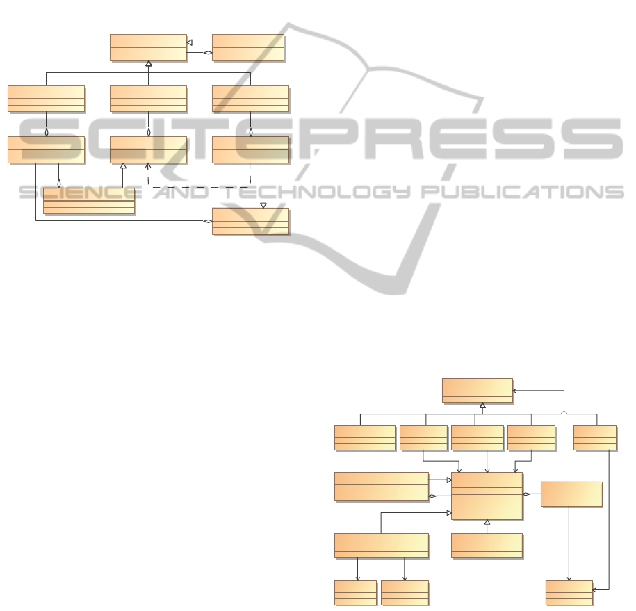
Figure 2: Basic Concepts in the Robotics API.
Additionally, states and sensors (cf. Fig. 2) can
be used in task descriptions. Sensors represent values
that are available (and can change) during the execu-
tion of robot tasks. They are provided by “typical”
sensor devices, such as laser rangefinders, light barri-
ers, or field bus inputs, as well as by actuators which
provide their state (joint angles, Cartesian position).
Other sensors might represent values that are con-
trolled from non-realtime Robotics API applications
(in cases where no exact timing is required). Further-
more, the results of real-time calculations working on
other sensor values are also sensor values. Sensor val-
ues provide (sensor) states and can be used in actions,
e.g. to describe sensor guarded motions.
States represent certain Boolean conditions of ac-
tions, actuators or sensors: Sensor states are either
Boolean-value sensors (where the sensor value “true”
means that the state is active), or conditions defined
on sensor values of other data types. Typical sensor
states might be a digital input being on or off, a force
sensor exceeding a specified force limit or the fact that
an obstacle has been detected by a laser range finder.
Action states describe certain progress properties of
an action. Examples are states telling that a certain
via-point of a trajectory has been passed, or that the
action has started or completed (i.e. the first or last
set-point has been produced). Actuator states include
certain error states of the device (e.g. that the com-
manded set-point is invalid or that an emergency stop
has occurred), and a completion state (whenever the
actuator has reached its latest set-point). Based on
these basic states, composed states are available, e.g.
when another state is not active, when two states are
active at the same time, or when another state has ever
been active.
Furthermore, the Robotics API supports a world
model to be used in actions and as sensors, which
can be seen as an independent extension to these basic
concepts and is not covered in this publication.
3 COMMANDS IN THE
ROBOTICS API
Robot tasks (with real-time requirements) in the
Robotics API are expressed as commands (cf. Fig. 3).
Such commands abstract from the concrete job per-
formed, and provide a common interface that allows
to start, stop, cancel or monitor the command.
A robot task consisting of an action for an actu-
ator is encapsulated as a runtime command. When
multiple (runtime) commands are to be executed with
given timing requirements, they have to be composed
into transaction commands. Each transaction com-
mand contains a set of initial commands (optionally
with start conditions) that will be executed once the
transaction command starts (if the corresponding start
condition holds), and a set of further commands that
are executed later based on events.
RuntimeCommand
TransactionCommand
EventEffect
WaitCommand
Command
External
EventHandler
Stop
State
StartCancel
Actuator
Raise
Action
1
1
1
0..1 0..1
1
1
1
Figure 3: Commands in the Robotics API.
In the context of a command, event handlers can
be defined. These monitor when a certain state (ac-
tion, device, sensor, composed or command state) is
entered, and perform one of the pre-defined effects.
ICINCO2012-9thInternationalConferenceonInformaticsinControl,AutomationandRobotics
152

For runtime commands, the following effects are al-
lowed:
• Stop forcefully stops the execution of the com-
mand, without giving the action or device any
chance to clean up or perform any further steps.
• Cancel asks the command to stop after bringing
the actuator into a secure, stable state. This state
must not require any other action to be executed
immediately. For a robot motion, Cancel should
brake the robot until halt, and then terminate the
command.
• Raise activates another state (that can be handled
in further event handlers).
• External effects notify the non-realtime applica-
tion that the event has occurred. Possible results
are starting a Robotics API thread or throwing an
exception to allow non-realtime error handling.
Due to their structure, transaction commands ad-
ditionally allow the event effect Start to start a child
command of the transaction. Furthermore, Stop and
Cancel can target the transaction command itself or
one specified child command. However, stopping an-
other command does not give it time to clean up and
can lead to unexpected consequences, thus it should
only be used in extreme cases. Instead, cancel is pre-
ferred. Stopping a transaction command always stops
all child commands immediately, but for cancel re-
quests the transaction command has to be configured
how to handle them (e.g. by forwarding them to some
of its child commands).
When controlling devices connected via field bus,
it is sometimes required to set one value, and then
wait for a given amount of time and reset the value.
Therefore, a third command type is available: Wait
commands remain active for the given wait period
(unless canceled), and are used to describe defined
time intervals between the execution of certain steps.
Additionally, by adding event handlers they can also
be used to wait for sensor events.
Transaction commands are also allowed to contain
further transaction commands as children, so complex
command structures can be built, e.g. for combining
typical coordination patterns such as parallel and se-
quential execution.
4 TRANSFORMING THE BASIC
CONCEPTS INTO RPI
In order to execute Robotics API commands with
real-time guarantees, they are transformed into a data-
flow graph for cyclic evaluation. The basic idea is to
transform the basic building blocks of the commands
into corresponding data-flow net fragments with cer-
tain responsibilities. These fragments are composed
according to given composition rules, leading to a
complete data-flow net that can be executed on a
Robot Control Core to create the behavior described
by the command.
Generally, states are described by Boolean data
flows, with “true” meaning that the state is currently
active. A state data flow is expressed by an output port
of a realtime primitive belonging to the net fragment
representing the context of the state (i.e. action, actua-
tor or sensor). The primitive net for a composed state
uses the Boolean outputs from the underlying states
and connects them to realtime primitives that perform
the correct computation (e.g. to express logical AND
or OR).
Robotics API actions just describe what task to
achieve (i.e. they only provide goals or open-loop set-
points to the actuator), but not how to execute the task
(i.e. they do not give differential equations or closed-
loop control laws – those would depend on knowing
the actual actuator and its state as a feedback). To
convert them into primitive nets, the corresponding
net fragments mainly have to provide one data flow
(of a simple or complex data type) containing the set-
point for the actuator. To provide these set-points, the
action fragment receives information about the active
and cancel state of its context (i.e. usually the run-
time command) using Boolean data flow ports, and
information about the global motion velocity override
factor. It uses (maybe stateful) calculation modules
to calculate the set-points that will be passed on to
the actuator. Furthermore, the action result contains
information about the type of the set-points created,
to allow the actuator to choose the right controller to
process them. This includes information whether the
set-point is to be interpreted as the point to reach in
the next execution cycle or as a goal to approach, as
well as exact data type information (e.g. that the value
gives the target transformation between a point on the
robot end-effector and a fixed point in the world). Ad-
ditionally, the action fragment has to provide Boolean
data flows for all the action states that can occur in the
action (e.g. progress states and completion when the
last set-point has been produced).
The actuator implementation has to be able to
process set-points and act according to those com-
manded values. Thus, the actuator net fragment is cre-
ated based on the type of action result (i.e. set-point)
received. The net fragment uses the data received
from the action result port, as well as state informa-
tion about the context (active, cancel, override), and
must contain realtime primitives that control the ac-
FromRobotCommandstoReal-timeRobotControl-TransformingHigh-levelRobotCommandsintoReal-timeDataflow
Graphs
153

tuator. Usually, it will also contain some kind of cal-
culation and controller implementation whenever the
input data cannot be directly forwarded to the hard-
ware. As outputs, the actuator fragment also has to
provide Boolean data flows for all possible actuator
states (especially actuator errors, and the completed
state when the set-point has been reached).
Applying a simple joint space point-to-point mo-
tion (action) to a 7-DOF manipulator (actuator) leads
to a net structure like the one given in Fig. 4: The
action is converted into a fragment containing trajec-
tory generators for each of the joints, reporting the 7
joint positions as set-points, and completion once all
trajectories are completed. The device fragment just
feeds the input values into the robot control block as
new position set-points.
Action (PTP)
Actuator (Robot)
Complete
true
te
Active
Active
Robot
Position
Ac
Ac
Ac
Cancel
Ca
Ca
Ca
Complete
Ac
Ac
Ac
Ac
Ac
Ac
Ac
Ac
Ac
Ac
Joint 1 Trajectory
J
J
J
And
Joint 7 Trajectory
J
J
J
………
Figure 4: Transformation result for a Point-to-point-motion
of a robot.
Net fragments for sensors have outputs for all the
supported sensor states, as well as one (maybe com-
plex type) output to provide the current value of the
sensor. Derived sensors use the result of the underly-
ing sensors, and perform calculations to provide their
own value. Typical examples for derived sensors are
data type dissectors that extract one component of a
complex data type (e.g. the x direction component of a
Cartesian force) or calculations performed upon sen-
sors such as addition, subtraction or comparison. The
sensor fragment is also responsible for creating the re-
altime primitives required to forward the sensor value
to the Robotics API application if requested (using a
best-effort strategy without real-time guarantees).
5 TRANSFORMING COMMANDS
INTO RPI
In order to execute a command, the corresponding
command fragment has to be created. Therefore,
all basic concepts of the command have to be trans-
formed into net fragments, as described in the previ-
ous section, and linked as described in the following
sections.
5.1 Combining Actions and Actuators
For runtime commands, the action and actuator frag-
ments have to be connected, sometimes requiring data
type conversions. To simplify the implementation of
action and device fragments, and to facilitate nested
actions where the outer action modifies the inner ac-
tion’s result, the conversions are not part of action or
actuator. Instead, both actions and actuator imple-
mentations may provide a set of data type converters
added to a net fragment in order to perform a “nat-
ural” translation between different data types. Typi-
cal converters include converting between joint space
and Cartesian space, and calculations on transforma-
tions and velocities. For example, a transformation
converter could use the given transformation matrix
between two frames to calculate the transformation
between two other frames using the defined world
model, similar to the tf library
3
in ROS. This way,
an action providing a desired transformation between
the tool center frame and the workpiece frame can di-
rectly be used with an actuator expecting joint angles
as set-points, using the converters provided by action
and actuator.
Converters often appear when working in Carte-
sian space, e.g. when applying an action “driveTo” to
a mobile robot platform. This asks the mobile robot
to drive to the given position based on odometry or
other position estimation available (without any ob-
stacle avoidance algorithms).
Action (driveTo)
Actuator (Robot)
Position
Monitor
Converter
Position
Transform
Complete
Complete
true
Goal
Position
Active
Active
Controller
Robot
Velocity
C
Ac
Ac
Cancel
Figure 5: Transformation result for a driveTo action and a
robot.
Fig. 5 shows the result of transforming the action
and the actuator: The action is transformed into a
value generator fragment that reports the destination
position (as configured in the driveTo action), and the
value “true” for the completion port. The robot part
mainly consists of one block that accepts Cartesian
velocities for the robot (that are internally converted
3
http://www.ros.org/wiki/tf
ICINCO2012-9thInternationalConferenceonInformaticsinControl,AutomationandRobotics
154

to wheel velocities). Additionally, to accept goal posi-
tions the robot needs a controller to convert goals into
small steps. In this case, a proportional controller is
added that uses the goal position and the estimated
current position to calculate a velocity for the mobile
robot, and reports “completed” once both positions
are sufficiently equal. Additionally, a frame transfor-
mation converter is used as the action does not de-
scribe the goal position of the robot in the origin of
odometry, but in some other coordinate system.
5.2 Transforming Runtime Commands
For the transformation of a runtime command, a net
fragment has to be created that contains input ports
for start, stop and cancel to control the life cycle of
the command. Additionally, the net fragment has an
input for the global velocity override, and contains the
net fragments for the command contents (i.e. action
and actuator fragment). Apart from this, command
fragments are self-contained and only have to pro-
vide Boolean output ports for states that occur during
execution of the command (especially the command
states active, started and complete).
Command fragments have to calculate an activa-
tion state based on the values from the start and stop
inputs (and possibly inner event handlers, see below),
and forward this active state as well as cancel and
override to the child fragments, such as action, ac-
tuator, sensor and composed state fragments. Con-
tinuing the example of Fig. 5, the runtime command
combining the action and actuator is converted into a
primitive net:
Command
Action
Actuator
Converter
Start
Stop
Active
Cancel
Ca
t
Activation
Started
Stop
Completion
true
Cancel
ar
t
t
t
t
t
t
t
t
t
t
t
t
A
op
op
op
Ca
Ca
Ca
St
St
St
St
St
C
C
Ac
Cancel
Termination
n
Complete
Figure 6: Transformation result for entire Platform.DriveTo
command.
Both the action and actuator fragment are con-
nected to the command activation part (as shown in
Fig. 6) which controls the active and cancel states of
the command. To make the command stop when ac-
tion and actuator are completed, their outputs are con-
nected to the stop input of the command activation.
Connecting the completed states of action and actua-
tor to the stop port of the command leads to a cycle
in the net data flow. To avoid such cycles in the net
structure (which would make a topological sorting of
the net and thus calculating an evaluation sequence
for the primitives impossible), the effects of all event
handlers (here the link to the Activation fragment’s
Stop port) are only forwarded in the next execution
cycle. This avoids cycles, but still guarantees that re-
actions to sensor events are executed in the evaluation
cycle following the occurrence of the event (e.g. in the
next millisecond for 1kHz).
Command fragments provide ports for command
and sensor states as well as composed states. Ad-
ditionally, runtime commands contain the action and
actuator fragments, and thus provide ports for action
and actuator states (forwarded from the correspond-
ing inner net fragment).
Event handlers react once the given (handled)
state and the command carrying the event handler
(context) is active, triggering the defined event effect.
The available event effects can mainly be split into
three different types:
• External effects are expressed by realtime prim-
itives that just propagate the monitored state or
event to the Robotics API application.
• Local effects such as stop or cancel (applied to the
same command the event handler belongs to) con-
tribute to the internal state calculation of the com-
mand fragments: When a stop occurs, the com-
mand has to be stopped even if there is no ex-
ternal stop request on the stop input of the frag-
ment. Thus, such events are connected to the cor-
responding port of the Activation part of the com-
mand fragment.
• Raise effects must ensure that the event handlers
for the raised state are executed. This is imple-
mented by returning the state handled by the Raise
effect as an additional reason for the raised state
(linked using a Boolean OR).
As a final step to execute a command, the com-
mand fragment’s inputs have to be connected. There-
fore, it is enough to connect the Stop input to “false”
and Start to “true”. Additionally, the Cancel input
has to be connected to the cancel primitive (notify-
ing about an external cancel request for the primitive
net), and a Termination primitive is required telling
when the net has completed. To achieve that, the com-
mand’s completed state (i.e. Boolean output) is used.
When ignoring all the intermediate structure of net
fragments and including just the primitives and links,
the entire representation is reduced to an executable
primitive net carrying the semantics of the given com-
mand.
FromRobotCommandstoReal-timeRobotControl-TransformingHigh-levelRobotCommandsintoReal-timeDataflow
Graphs
155
5.3 Transforming Transaction
Commands
Command fragments for transaction commands have
a similar structure, but contain command fragments
for all child commands instead of action and actuator
fragments.
The transformation of a transaction command
with event handlers is shown in the next example, a
transaction controlling a parallel gripper. The grip-
per is assumed to be connected to digital field bus
inputs and outputs. To open the gripper, a transac-
tion command is used that first sets the “open” digital
output to true, then waits for a rising edge on the “po-
sition reached” input, and resets the “open” output to
false. Additionally, when the command is canceled,
the “open” output is also reset to false.
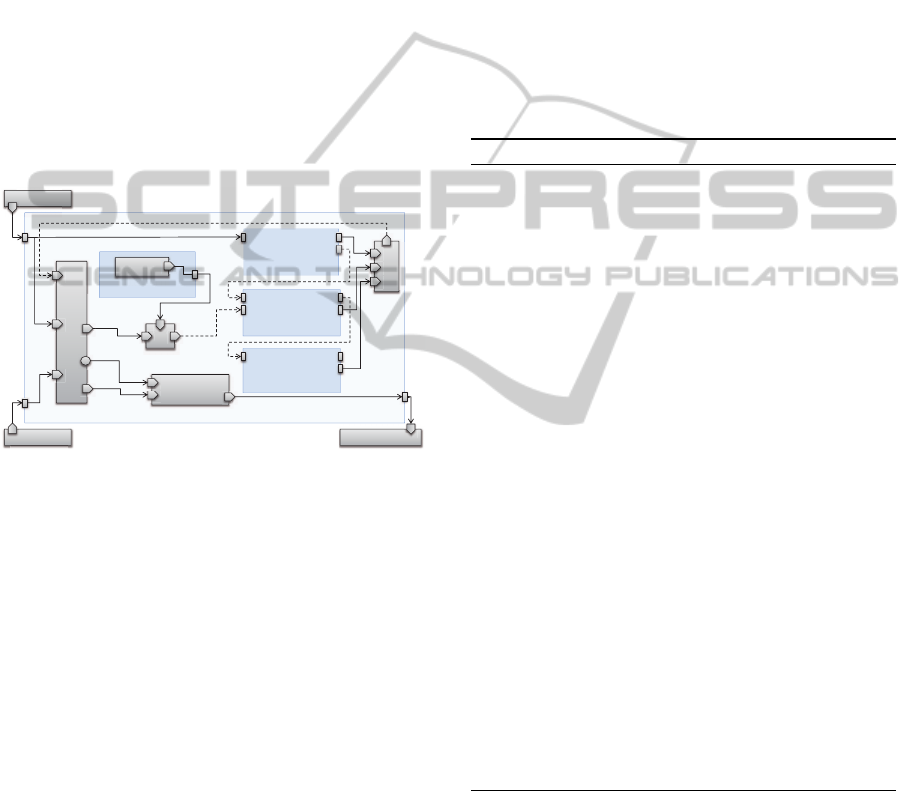
Command (Transaction Gripper.Open)
true
Cancel Termination
o
n
n
n
n
n
n
n
Sensor (reached)
(
Input
Command (setTrue)
Complete
Start Active
Command (setFalse)
Start
St
Complete
Active
Command (Wait)
Start
S
Cancel
Complete
Active
Or
O
O
O
Stop
St
S
Completion
C
C
C
Complete
Start
Stop
Active
Cancel
t
Activation
Started
ar
t
t
t
t
t
t
t
t
t
t
t
t
t
op
op
op
C
St
St
Ac
Cancel
Figure 7: Transformation result for a transaction opening a
gripper.
The resulting net structure is depicted in Fig. 7.
It mainly consists of an activation part similar to the
one shown for runtime commands, and the fragments
created for the child commands which have a struc-
ture similar to the one shown in Fig. 6. The trans-
action command stops itself once none of the child
commands is active any more.
To implement the local stop event effect on trans-
action command, all child commands are stopped (via
their stop input). However, the cancel effect is not di-
rectly handled or automatically forwarded to the child
commands, but the cancel event handlers for the trans-
action command are triggered (that may explicitly
forward the cancel request to some of the children). In
addition to these event effects and the ones described
for runtime commands, transaction commands allow
start, stop and cancel to be applied to their child com-
mands. These events trigger the corresponding input
of the child command, using delayed links. In the
example, the children are connected by such delayed
links representing the event handlers used to specify
the execution order of the commands. If multiple rea-
sons lead to a certain effect on a command (here the
external cancel request and the sensor event both can-
cel the wait command), these reasons are combined in
a disjunction.
As transaction command fragments contain frag-
ments for their child commands, they also provide
ports for their states. This allows to add event han-
dlers to a transaction command that react to states or
events that occur in commands nested deeper in the
command structure.
5.4 Transformation Algorithm
Algorithm 1 gives an overview over the mapping pro-
cess for commands:
Algorithm 1: transformCommand(c: Command).
activation ← createActivation()
if c is RuntimeCommand then
action ← transformAction(c.action)
device ← transformDevice(action, c.device)
connect(action.result, device.input)
else if c is TransactionCommand then
for all cc: child commands do
child ← transformCommand(cc)
for all h: event handlers do
if h affects cc then
event ← transformEvent(h.event)
connect(event, child.activation)
end if
end for
end for
end if
for all h: event handlers do
if h affects c then
event ← transformEvent(h.event)
connect(event, activation)
end if
end for
for all conn: connections do
if conn.from.type 6= conn.to.type then
addConverter(conn)
end if
end for
First the activation part and the command contents
are created. For runtime commands, this includes
transforming the action and device as described in
Sect. 5.1, for transaction commands the child com-
mands are transformed recursively and connected as
described in Sect. 5.3. After that, all event handlers
are transformed and connected as given in Sect. 5.2,
and all required data type converters are added and
connected.
ICINCO2012-9thInternationalConferenceonInformaticsinControl,AutomationandRobotics
156
6 EXPERIMENTAL RESULTS
To show the feasibility of our approach, we developed
a reference implementation, and used it in multiple
examples. With this implementation, we are able to
successfully execute the commands presented in this
paper as well as much larger real-time transactions.
Force controlled manipulator motions with synchro-
nized tool actions, resulting in primitive nets with up
to 1000 calculation primitives
4
, can reliably be evalu-
ated at a 1 kHz rate.
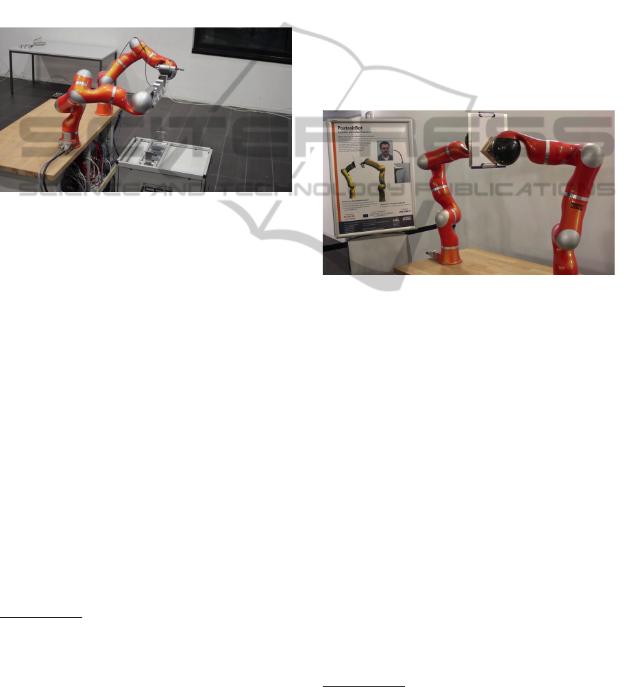
Figure 8: Factory 2020 scenario.
Our first example called Factory 2020
5
uses this
approach to control a Segway mobile platform and
two KUKA lightweight robots (Bischoff et al., 2010)
in a future factory scenario. It is programmed entirely
in Java using a service-oriented architecture. This
example includes the driveTo command from Fig. 5
applied to the Segway platform, as well as complex
command structures for the two lightweight robots. It
makes heavy use of the torque sensors integrated into
the robot axes that can be easily programmed through
the Robotics API:
• The exact location of workpiece container de-
livered by the mobile platform is determined by
moving the robot until contact. Therefore, a robot
motion command is built, and an event handler is
added that stops the command once the force sen-
sor of the computed end-effector force exceeds a
given limit.
• When loosening or tightening screws, the robot
uses compliance to follow the screw motion and
maintain the required pressure. To achieve this,
transaction commands are used to coordinate and
synchronize the screw driver actions (that can be
4
Our reference implementation uses fine-grained com-
putation blocks, multiple of which are used to express
the primitives in the previous figures. For example, our
BooleanAnd primitive only accepts two inputs, so multiple
are required to compute the action completion in Fig. 4.
5
http://video.isse.de/factory
expressed by switching digital outputs) and the
robot motion (that uses the Cartesian compliance
mode of the underlying lightweight robot).
Additionally, both lightweight robots cooperatively
carry the workpiece containers from the mobile plat-
form to the working area (as shown in Fig. 8), requir-
ing real-time synchronization of both robots. This is
achieved by creating the same motion command for
both robots (i.e. describing the same Cartesian path)
using different motion centers, and placing both com-
mands into one real-time transaction as start com-
mands.
In this scenario, we reduced the execution fre-
quency to 500 Hz, as some of the more complex prim-
itive nets, especially when controlling both robots si-
multaneously, exceeded 1 ms computation time.
Figure 9: PortraitBot.
The second example, PortraitBot
6
(Fig. 9), con-
tains two lightweight robots that cooperatively draw
a portrait captured from a webcam. The first robot
is holding the drawing area, while the second draws
the edges detected in the webcam image. As the first
robot is allowed to move during drawing, this exam-
ple contains full motion cooperation (as opposed to
the pure synchronization in the first example). From
the programmer point of view, it is not important that
the drawing area can move, as the required transfor-
mation calculations are automatically added through
the converters described in Sect. 5, as long as the
frame graph in the Java application is set up correctly
(i.e. the drawing area frame is attached to the first
robot’s flange frame).
7 CONCLUSIONS
In this paper, we have described an extensible frame-
work, the Robotics API, for defining robot tasks in
a non-realtime context, including the concepts re-
quired to specify sensor-guided actions and real-time
6
http://video.isse.de/portrait
FromRobotCommandstoReal-timeRobotControl-TransformingHigh-levelRobotCommandsintoReal-timeDataflow
Graphs
157

reaction to specific events. This framework allows
to define real-time transactions where multiple steps
have to be executed with timing constraints in a given
sequence or as reaction to certain events. Further-
more, this approach incorporates means to specify
safe strategies that are to be applied when errors occur
or the task was canceled. Based on these high-level
command descriptions, we introduced an algorithm to
transform them into a low-level dataflow language, so
that they can be executed on a robot controller with
real-time guarantees.
Upon this foundation, high-level features such as
advanced error handling on the non-realtime side can
be implemented and provided. To achieve this, real-
time reaction to error events within transaction com-
mands is used to bring the robot into a stable state,
and an exception on the Java side is thrown to in-
voke error handling in the application. Furthermore,
we have experimented with strategies to safely switch
between two real-time transactions while the robot
is still in motion. For industrial robots, this can be
used to change the executed task without requiring the
robot to stop during the task switch (e.g. for blending
motions). We are also currently working on ways of
describing the robot transactions and command coor-
dination in an even more user-friendly way, such as
through recurring patterns and graphical editors for
state charts or flow charts.
ACKNOWLEDGEMENTS
This work presents results of the research project Soft-
Robot which was funded by the European Union and
the Bavarian government. The project was carried
out together with KUKA Laboratories GmbH and
MRK-Systeme GmbH and was kindly supported by
VDI/VDE-IT.
REFERENCES
Andr
´
e, C. (1996a). Representation and analysis of reactive
behaviors: A synchronous approach. In Proc. IMACS
Multiconference on Computational Engineering in
Systems Applications, pages 19–29, Lille, France.
Andr
´
e, C. (1996b). SyncCharts: A visual representation of
reactive behaviors. Technical Report RR 95–52, rev.
RR (96–56), I3S/INRIA, Sophia-Antipolis, France.
Angerer, A., Hoffmann, A., Schierl, A., Vistein, M., and
Reif, W. (2010). The Robotics API: An object-
oriented framework for modeling industrial robotics
applications. In Proc. 2010 IEEE/RSJ Intl. Conf. on
Intelligent Robots and Systems (IROS 2010), Taipeh,
Taiwan, pages 4036–4041. IEEE.
Bischoff, R., Kurth, J., Schreiber, G., Koeppe, R., Albu-
Sch
¨
affer, A., Beyer, A., Eiberger, O., Haddadin, S.,
Stemmer, A., Grunwald, G., and Hirzinger, G. (2010).
The KUKA-DLR lightweight robot arm - a new ref-
erence platform for robotics research and manufactur-
ing. In Proc. IFR Int. Symposium on Robotics (ISR
2010).
Borrelly, J.-J., Coste-Mani
`
ere, E., Espiau, B., Kapellos, K.,
Pissard-Gibollet, R., Simon, D., and Turro, N. (1998).
The ORCCAD architecture. Intl. J. of Robotics Re-
search, 17(4):338–359.
Bruyninckx, H. (2001). Open robot control software: the
OROCOS project. In Proc. 2001 IEEE Intl. Conf. on
Robotics and Automation, pages 2523–2528, Seoul,
Korea.
Caspi, P., Pilaud, D., Halbwachs, N., and Plaice, J. A.
(1987). LUSTRE: A declarative language for real-
time programming. In Proc. 14th ACM SIGACT-
SIGPLAN Symposium on Principles of Programming
Languages, pages 178–188, Munich, Germany.
Hoffmann, A., Angerer, A., Ortmeier, F., Vistein, M., and
Reif, W. (2009). Hiding real-time: A new approach
for the software development of industrial robots. In
Proc. 2009 IEEE/RSJ Intl. Conf. on Intelligent Robots
and Systems (IROS 2009), St. Louis, Missouri, USA,
pages 2108–2113. IEEE.
MacKenzie, D. C., Arkin, R., and Cameron, J. M.
(1997). Multiagent mission specification and
execution. Autonomous Robots, 4:29–52.
10.1023/A:1008807102993.
Peterson, J. L. (1981). Petri Net Theory and the Modeling
of Systems. Prentice Hall PTR, Upper Saddle River,
NJ, USA.
Pires, J. N. (2009). New challenges for industrial robotic
cell programming. Industrial Robot, 36(1).
Schneider, S. A., Chen, V. W., Pardo-Castellote, G., and
Wang, H. H. (1998). ControlShell: A software archi-
tecture for complex electromechanical systems. In-
ternational Journal of Robotics Research, 17(4):360–
380.
Simmons, R. and Apfelbaum, D. (1998). A task description
language for robot control. In Proc. 1998 IEEE/RSJ
Intl. Conf. on Intelligent Robots and Systems, Victoria,
Canada.
Smits, R., Laet, T. D., Claes, K., Bruyninckx, H., and Schut-
ter, J. D. (2008). iTASC: a tool for multi-sensor inte-
gration in robot manipulation. In Proc. IEEE Interna-
tional Conference on Multisensor Fusion and Integra-
tion for Intelligent Systems.
Soetens, P. and Bruyninckx, H. (2005). Realtime hybrid
task-based control for robots and machine tools. In
Proc. 2005 IEEE Intl. Conf. on Robotics and Automa-
tion, pages 259–264, Barcelona, Spain.
Vistein, M., Angerer, A., Hoffmann, A., Schierl, A., and
Reif, W. (2010). Interfacing industrial robots using
realtime primitives. In Proc. 2010 IEEE Intl. Conf. on
Automation and Logistics (ICAL 2010), Hong Kong,
China, pages 468–473. IEEE.
ICINCO2012-9thInternationalConferenceonInformaticsinControl,AutomationandRobotics
158
