
COMPACT GAN HIGH POWER AMPLIFIERS
FOR SPACE COMMUNICATION, SENSING
AND GREEN POWER TRANSMISSION
Shigeo Kawasaki and Yuta Kobayashi
ISAS/JAXA, Sagamihara, Japan
kawasaki.shigeo@jaxa.jp, kobayashi.yuta@jaxa.jp
+81-50-3362-5732, +81-50-3362-6450
Keywords: Gallium nitride, High power amplifier, Microwave power transmission, Aerospace electronics, Space
Communication
Abstract: On the base of a green-eco technology, S-bandhigh power GaN amplifiers have been developed with a
microwave power transmission function in the space electronics equipment. High DC-to-RF conversion
efficiency of 63 % was achieved in the 20W GaN amplifier operating at 2.25 GHz and its design technique
was extended to realize 1 kW SSPA for the space communication. Furthermore, wireless sensor operation
and battery charging was also demonstrated by means of microwave power transmission.
1 INTRODUCTION
The RF technology has been used for
communication and sensing, so far. As the third
usage of the microwaves, wireless power
transmission and energy harvesting have been paid
much attention as one of solutions of environmental
problems. With the enormous interest brewing,
researchers around the world started to develop the
wireless energy transfer/power transmission and
energy harvesting/scavenging. This is the green-eco
wireless power technology for the green life
(environmental issues), ecology (nature-human
interaction) and economy (cost effectiveness).
Specifically, it will have a great impact on many
applications such as compact and battery-less
wireless communications and wireless sensor
systems. Wireless power delivery generated from
clean energy may be called wireless green power
transmission.
The wireless power transmission (WPT) is usually
categorized into three, the EM Coupling, the
Magnetic Resonance (MR), and the Microwave
WPT (MPT). It has been known that the carrier
wave without modulation can be delivered the
energy wirelessly. This is the basic feature of MPT.
Comparing with wired systems and other WPT
technologies, the MPT has become one of the most
important technologies on demand to future space
missions as well as green eco technologies (N.
Shinohara, 2009). For instance, the MPT module
with some sensors can reinforce health monitoring
functions in a space craft without wire-harness and
solve a payload problem by removing some of
onboard electrical power subsystems (EPS) in the
space craft.
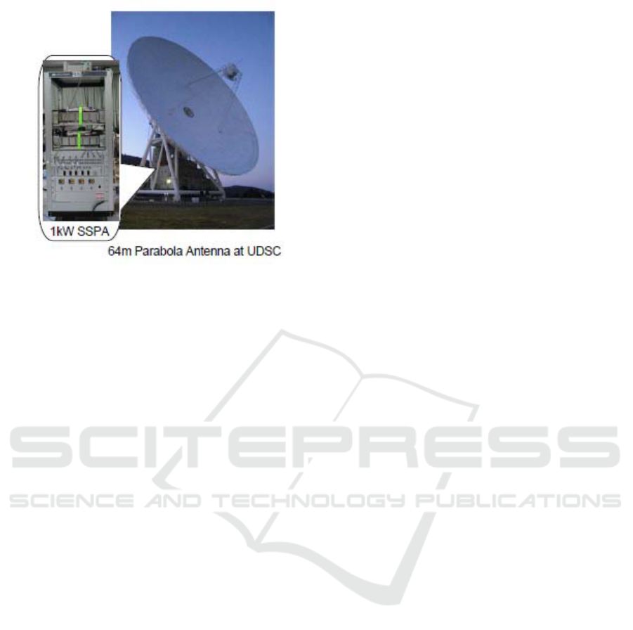
Reading the space electronics, a compact
communication system is needed both in the
onboard communication system and in the ground
station. On behalf of operation of a space ground
station, such as the Usuda Deep Space Center
(UDSC) shown in Fig. 1, a high power and high
efficiency solid state power amplifier is strongly
requested. For this purpose, a wide band-gap
semiconductor such as GaN and SiC is promising.
Further, reduction of payload is important issue in
the onboard system. In order to solve this problem,
realization of a high power and high efficiency RF
amplifier using the wide band gap semiconductor is
requested. This is also the effective solution for the
single event, total dose radio-isotope problem, and
high temperature operation (N. Adachi, 2005).
Regarding power receiving in the MPT, power
detection by a rectenna directory connected with an
antenna and a detector is typical (M. Furukawa,
2006) (M. Hori, 2011) (T. ITO, 1979). As described
before, wireless power is intentionally delivered to
the rectenna. In the case of MPT, the high
44
Kawasaki S. and Kobayashi Y.
COMPACT GAN HIGH POWER AMPLIFIERS FOR SPACE COMMUNICATION, SENSING AND GREEN POWER TRANSMISSION.
DOI: 10.5220/0005413700440051
In Proceedings of the First International Conference on Telecommunications and Remote Sensing (ICTRS 2012), pages 44-51
ISBN: 978-989-8565-28-0
Copyright
c
2012 by SCITEPRESS – Science and Technology Publications, Lda. All rights reserved
breakdown-voltage RF detector is required to obtain
high converted DC power, for instance, battery
charging due to MPT. On the other hand,
electromagnetic energy harvesting can be done in
the RF environment. This harvester also consists of
the rectenna but the harvested RF energy includes
leaked RF energy from a transmitter in other place.
The harvesting energy which tune into RF energy
may include that from a energy converter/transfer.
When the collected energy is weak, this may be
called as “scavenging”.
In this paper, the wireless power transmission is
explained as the green-eco technology. From this
view point, demonstration of space communication
and wireless sensor by means of microwave power
transmission is described by using high power GaN
amplifiers. The 1kW SSPA combined with the high
power GaN amplifiers is shown.In addition, thermal
sensor operation and battery charging by microwave
power transmission are introduced.
2 MICROWAVE GAN CIRCUITS
FOR SPACE
COMMUNICATION AND MPT
2.1 Semiconductor devices
In space communication, high efficient power device
is necessitated. In this view point, a wide band-gap
semiconductor is very promising. Among them, the
gallium nitride (GaN) has recently been focused on
as a high power and high efficiency device in the
microwave region. Therefore, the GaN is one of the
most significant elements to achieve effective use of
energy in space not only for communications but
also for power transmissions. The GaN has several
superior material properties, such as wide band gap,
high saturation velocity, and good thermal
conductivity. Due to these properties, the GaN is
considered to have advantages in high efficiency,
and high temperature conditions in addition to the
high power characteristics. Thus, GaN is expected to
be used in space applications such as, high power
amplifiers (DC-to-RF conversion modules) and
rectifiers (RF-to-DC conversion modules).
Fig. 1.The kW-class SSPA for the space communication
2.2 High power amplifiers
The S-band GaN based high power amplifiers
(HPAs) have been designed, developed, and
evaluated for space applications of the
communication, a wireless sensor and microwave
energy transfer intended for the green-eco
technology. As examples for the onboard
application, the 20W and 100W GaN amplifiers with
the high power added efficiency were developed.
2.2.1 The 20W-class GaN HPA
The 20-W-class single-stage high power amplifier
was designed in the S-band by using the commercial
available CAD(Agilent: Advanced Design System)
with small signal S-parameters. The package type of
20-W-class GaN HEMT on a Si substrate and the
circuit substrate (Rogers RO4350 : the copper
thickness of 70 um, the substrate thickness of 0.762
mm, the permittivity of 3.46) were used. The size of
the 20-W-class amplifier was 50*55*17 mm. The
circuit overview is shown in Fig. 2.
The measured small signal S-parameters from the
20W-class GaN HPA are shown in Fig. 3. Between
2.1 and 2.4 GHz, it was observed from Fig 3 that
peaks of measured return loss of S11 and S22were
achieved below -10 dB and the peak of measured
forward gain of S21 was larger than 15 dB. In
addition, characteristics of input-output, gain, drain
efficiency and power added efficiency (PAE) from
the fabricated 20W HPA at 2.25 GHz are shown in
Fig. 4. It is confirmed that P1dB and P3dB were
42.2 dBm and 43.7 dBm and the PAE at these points
were 55.1 % and 63.3 %, respectively. (Y.
Kobayashi, 2012)
2.2.2 The 100W-class GaN HPA Unit
The 100-W-class single-stage high power amplifier
was also designed and fabricated in the S-band with
the package type 100W-class GaN HEMT on the Si
substrate and the circuit substrate (RogersRO4350).
The size of the 100-W-class is 100*76*30 mm
shown in Fig. 5.
Compact Gan High Power Amplifiers for Space Communication, Sensing and Green Power Transmission
45
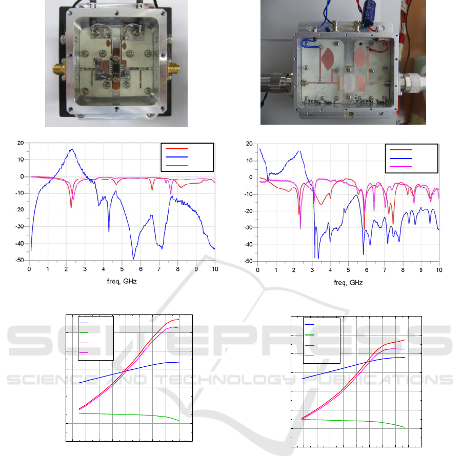
Fig. 5. 100 W-classGaN HPA
S11
S21
S22
Fig. 6. Measured S-Parameters
20 22 24 26 28 30 32 34 36 38 40
0
10
20
30
40
50
60
70
0
10
20
30
40
50
60
70
Pin[ dBm]
Pout[dBm],Gain[dB],η [%],PAE[%]
NPT25100: Vds:28 V, Freq:2.25 GHz
Pout
Gain
η
PAE
Fig. 7. Input-output characteristics
Fig. 2. 20 W-classGaN HPA
S11
S21
S22
Fig. 3. Measured S-Parameters
16 18 20 22 24 26 28 30 32 34
0
10
20
30
40
50
60
70
0
10
20
30
40
50
60
70
Pin[ dBm]
Pout[dBm],Gain[dB],η [%],PAE[%]
NPT25015: Vds:28 V, Freq:2.25 GHz
Pout
Gain
η
PAE
Fig. 4. Input-output characteristics
The measured small signal S-parameters of the
100W-class GaN HPA are shown in Fig. 6. In this
figure, it was found that the S11 was measured with
smaller than -11 dB, the S22 was smaller than -6.5
dB, and S21 was larger than 15 dB at the frequency
rangebetween 2.1-2.4 GHz. In addition, the input-
output characteristics of the 100W-class HPA at
2.25 GHz are shown in Fig. 7. It is confirmed that
P1dB and P3dB were 45.3 dBm and 48.0 dBm and
the power added efficiency (PAE) at these points
were 43.0 % and 52.6 %, respectively.
First International Conference on Telecommunications and Remote Sensing
46
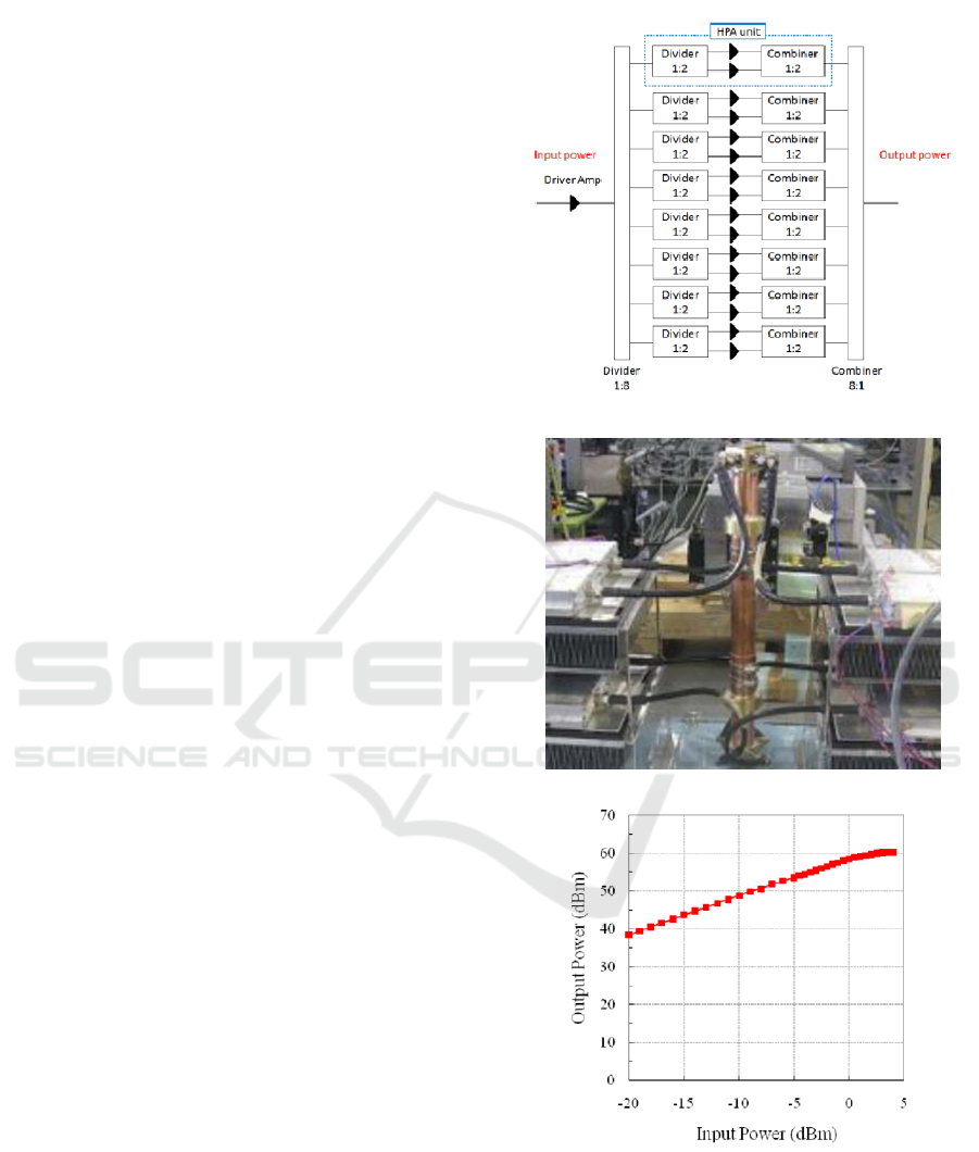
Fig. 8. Block diagram of 1-kW-class GaN HPA equipment
Fig. 9. 1-kW-class GaN HPA equipment
Fig. 10. 1-kW-class HPA equipment characteristics
3 APPLICATION AND TEST
For the space green power transmission as well as
the ground-to-satellite application, the 1 kW GaN
solid state power amplifier (SSPA) using a power
combiner technique was fabricated. The total DC-to-
RF conversion efficiency of more than 50 % was
achieved. Using these components, some
preliminary experiments of space power
transmission have also been conducted.
Wireless power transmission (WPT) is one of the
most important technologies for future space
missions. WPT can be applied to not only inside of
space crafts but also outside of ones. Comparing
wired systems, there are various advantages using
WPT. For instance, WPT with some sensors can
easily reinforce health monitoring functions of space
crafts and WPT between space crafts will be able to
reduce onboard electrical power subsystems (EPS)
of each space craft. However, the resources such as
size, weight, power consumptions are generally
limited in a space craft. In addition, mission
requirements and environments are completely
different in each mission, especially in space science
or space exploration missions. Besides, from a radio
frequency (RF) technical standpoint, the higher the
frequency of WPT is, the smaller the size of WPT
components become. However, in high-frequency
WPT, circuit designs are more complicated and free-
space span losses are larger than those of low-
frequency WPT. Therefore, the specifications of
WPT such as frequency, power, etc. must not be
determined without considering both mission
requirements and RF features.
3.1 High power GaN amplifier
combiner for space communication
ground station
A 1kW-class GaN high power amplifier equipment
was designed and fabricated in the S-band. It
consists of three parts, a GaAs driver amplifier,
200W-classs high power amplifier units and a
circular waveguide combiner. The Block diagram
and overview of 1kW-class GaNSSPA Unit are
shown in Fig. 8 and Fig. 9, respectively.
Input-output characteristics of the 1kW-class
SSPA Unit including nonlinear amplification at 2.1
GHz, allocated for earth-to-space link are shown in
Fig. 10. More than 60 dBm output power was
achieved in this evaluation. In addition, measured
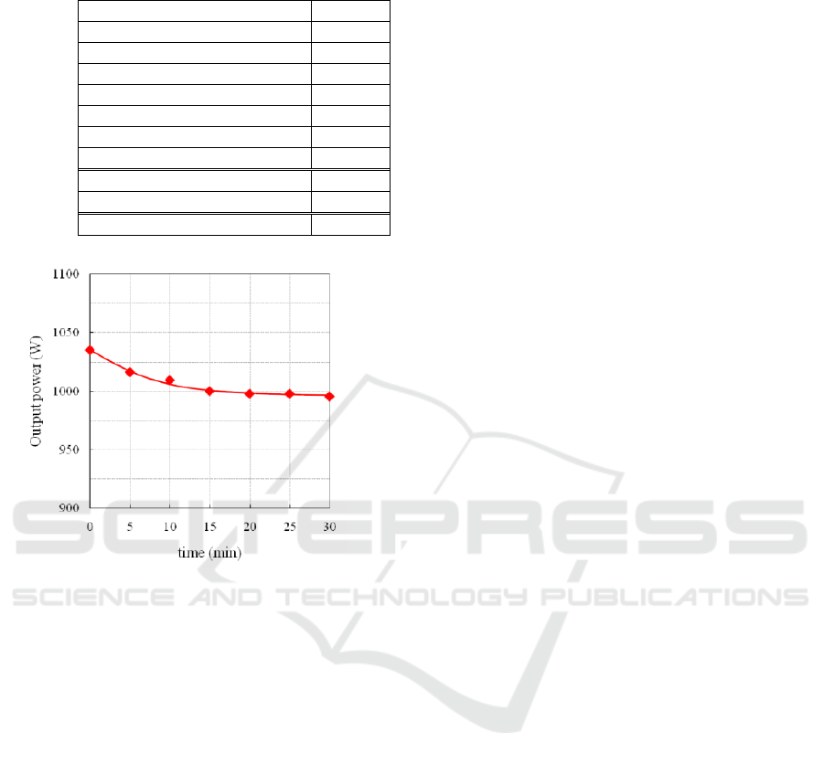
combining efficiency can be seen in table 1. High
combining efficiency of 87.1 % was obtained.
Further, the output power stability during more than
half an hour operation is shown in Fig. 11. About 5
% degradation of the output power was observed. (H.
Noji, 2011)
Compact Gan High Power Amplifiers for Space Communication, Sensing and Green Power Transmission
47
3.2 The wireless sensor and batter
charging by MPT
The applications of GaN modules for space use are
numerous such as onboard communication system,
ground station communication system, wireless
power transmission system, and wireless sensor
network system. Here, the combination of
microwave power/energy transmission with the
sensor network, namely the wireless sensor and
energy transfer (WiSEnT), was conducted. The
WiSEnT with a thermal sensor was evaluated inside
an anechoic chamber as the first step toward future
spacecraft health monitoring system. The thermal
sensor was connected with the rectifier directly and
it can operate without any batteries. The thermal
sensor was operated as the normal sensor system
with a battery and the fundamental data were
obtained through the preliminary experiment. These
are indicated in Fig. 12.
Further, the application of the GaN based HPA to
MPT for the purpose of battery charging with a
rectifier was checked inside an anechoic chamber.
The block diagram of MPT experiment is shown in
Fig. 13. The inside and outside appearances of the
anechoic chamber are shown in Fig. 14 and 15
respectively. In Figs. 13 and 14, the distance
between transmission and receiving antenna was 1.2
m.
Table 1 Combining efficiency of
1-kW-class HPA equipment
HPA1 output power 158.5 W
HPA2 output power 141.3 W
HPA3 output power 154.9 W
HPA4 output power 147.9 W
HPA5 output power 154.9 W
HPA6 output power 138.0 W
HPA7 output power 147.9 W
HPA8 output power 144.5 W
Total input power to combiner 1188 W
Output power from combiner 1035 W
Combining efficiency 87.1 %
Fig. 11. Ouput power stability of
1-kW-class HPA equipment
In Fig. 13, 2.25 GHz sine wave generated by the
SG was amplified by the GaN HPA. Then, the
amplified signal was supplied to the divider. After
that, the divided signals were radiated by the 16-
element transmission array antenna. The radiated
signal was received by the 16-element receiving
array antenna and combined by the power combiner.
Then, the combined signal was converted into DC
signal by the rectifier. After that, the DC signal was
supplied to the DC/DC converter and the converted
signal was supplied to the battery. The transmission
and receiving RF powers divided by directional
couplers were measured by power meters. The
measured power of transmission antenna (EIRP) and
that of rectifier realized 58.8 dBm and 33.3 dBm,
respectively.
The battery voltage during the MPT experiment is
shown in Fig. 16. The Figure 16 indicates that the
charging achieved totally up to 1615.5 Ws (=0.449
Wh) in about 6 hours 43 minutes. The DC/DC
converter was inserted between the rectifier and the
battery so as to keep the conversion efficiency of the
rectifier high. In general, the efficiency strongly
depends on the load resistance of a rectifier and it is
important to keep the resistance at the optimum
value. However, a load resistance of a battery is
usually changing while it is charging. Therefore,
when the output signal of a rectifier is directly
supplied to a battery, the conversion efficiency
changes widely. In Fig. 13, however, it is indicated
that the battery charging rate was not constant.
Therefore, the load resistance of the rectifier must
have been changing although the DC/DC converter
was used.
First International Conference on Telecommunications and Remote Sensing
48
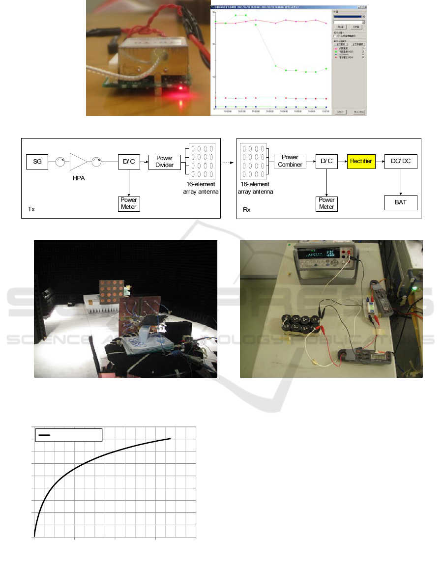
Fig. 12. The preliminary experiment for the thermal sensor operating with microwave power transmission
Fig. 13. Block diagram of WPT experiment
16‐element‐transmission
arrayAntenna
Rectifier
16‐element‐receiving
arrayAntenna
Powerdivider
Powercombiner
DC/DC
converter
Batteryvoltagemeter
Battery
Rectifier
output
signal
Fig. 14.Componentsused inside of anechoic chamber Fig. 15. Components used forbattery charging
3.3 Space environmental testing
For an actual space use, the space environmental
testing such as temperature, thermal vacuum, and
radiation are significant. GaN is expected to tolerate
these harsh environmental testing due to its
characteristics. The space environmental testing
listed in table 2 was conducted with the 20-W-class
GaN HPA. The test facilities are shown in Fig. 17.
0
2
4
6
8
10
12
14
16
18
02468
BatteryVoltage[V]
time[hour]
BatteryVoltage
Fig. 16. Battery voltage
Compact Gan High Power Amplifiers for Space Communication, Sensing and Green Power Transmission
49
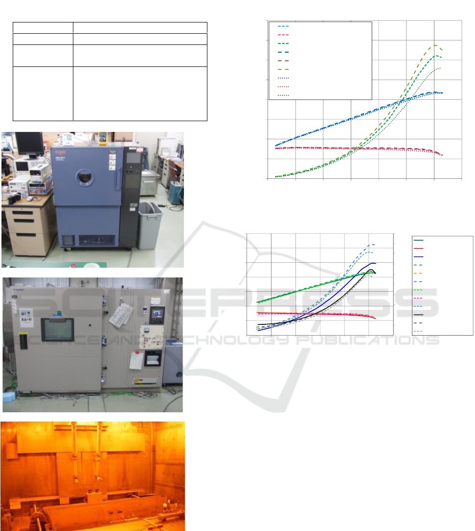
Results of thermal vacuum testing and radiation
testing are shown in Figs. 18 and 19 respectively.
Figure 18 indicates that the GaN amplifier continued
to function normallyduring the thermal cycle
although the PAE of each temperature were a little
different. Further, Fig. 19indicates theGaN amplifier,
once degraded by the radiation, came back to its
previous operation by the aging test. This is named
as annealing effect. From these results, it was greatly
enhanced that the GaN will be able to be used in the
space.
Table 2
Conditions of space environmental testing
Test name Conditions
Temperature -5 degC ,25 degC, 55degC
Thermal
vacuum
Thermal cycle(-20 to 60 degC)
1E-4 ~ 1E-3 Pa
Radiation
60
Co, Total Ionizing Dose (TID) :
320 krad (Rate: 20krad/h)
(After radiation test, aging test was
done.) (100 degC, 168hours
continuous operation)
(a) Temperature
(b) Thermal vacuum
©JAEA
(c) Radiation (@JAEA)
0
10
20
30
40
50
60
70
80
0 5 10 15 20 25 30 35
Pout[dBm],Gain[dB],PAE[%]
Pin[dBm]
Thermalvacuum(25℃,‐20℃,60℃)(NPT25015@2.25GHz)
Pout(25℃,1.7E‐3Pa)
Gain(25℃,1.7E‐3Pa)
PAE(25℃,1.7E‐3Pa)
Pout(‐20℃,5.2E‐4Pa)
Gain(‐20℃,5.2E‐4Pa)
PAE(‐20℃,5.2E‐4Pa)
Pout(60℃,1.3E‐3Pa)
Gain(60℃,1.3E‐3Pa)
PAE(60℃,1.3E‐3Pa)
Fig. 18. Result of thermal vacuum testing
0
0.2
0.4
0.6
0.8
1
1.2
1.4
1.6
1.8
2
0
10
20
30
40
50
60
70
5 101520253035
Ids[A]
Pout[dBm],Gain[dB],PAE [%]
Pin[dBm]
NPT25015
Pout[dBm](afterTID)
Gain[dB](afterTID)
PAE[%](afterTID)
Pout[dBm](beforeTID)
Gain[dB](beforeTID)
PAE[%](beforeTID)
Pout[dBm](afteraging)
Gain[dB](afteraging)
PAE[%](afteraging)
Ids[A](afterTID)
Ids[A](beforeTID)
Ids[A](afteraging)
Fig. 19. Result of radiation testing
4 SUMMARY
In this paper, the design, fabrication, and evaluation
of high power and high efficiency GaNHPAs were
described. Further, the battery charging experiment
for the space MPT to a rover was demonstrated. In
addition, the environmental testing results for space
use are shown.
The 20W-class GaNHPA realized 43.7 dBm
output signal power with 63.3 % PAE at 2.25 GHz,
the 100W-clas HPA realized 48.0 dBm with 52.6 %,
First International Conference on Telecommunications and Remote Sensing
50

and 1kW-class SSPA unit realized 60.1 dBm output
signal power with 87.1 % combining efficiency at
2.1 GHz.The experiments of thermal sensor
operation and battery charging by MPT using the
GaN HPAs werecarried out. The thermal sensor
operated as the normal one with a battery supported
by MPT. In addition, the battery was charged up by
the converted DC power under the condition where
the EIRP was 58.8 dBm, the rectifier input power
was 33.3 dBm, and the distance between the power
transmitter and the receiver was 1.2 m. Further, the
GaN amplifier could continue to function normally
during the space environmental testing of
temperature, thermal vacuum, and radiation.
Through these experiments, it is believed that
flexibilities for the future missions in terms of size,
weight, and power consumption using GaN will be
improved.
ACKNOWLEDGEMENTS
The authors would like to express deep gratitude to
Mr. S. Furuta, Mr. Y. Moriguchi, and Mr. M. Ono,
NEC Network and Sensor Systems, Ltd for their
great support in developing GaN amplifiers. In
addition, the authors appreciate to Dr. S. Yoshida
and Prof. Z. Yamamoto, ISAS/JAXA, for their
fruitful discussion, encouragement and information
of the space ground station.
REFERENCES
N. Shinohara and S. Kawasaki., 2009. Recent Wireless
Power Transmission Technologies in Japan for Space
Solar Power Station/Satellite.RWS2009 Digest,
MO2A-4, San Diego, Jan. 2009, pp. 13-15.
M. Furukawa, et al, 2006. 5.8-GHz Planar Hybrid
Rectenna for Wireless Powered Applications,
APMC2006 Digest, FR2E-1, Yokohama, Dec. 2006.
M. Hori, et al., 2011. The 5.8GHz Receiving and Rectenna
Arrayfor Wireless Communication and Power
Transmission, IEICE technical report in Japanese,
MW2010-135(2011-1), Jan. 2011.
T. Ito, et al., 1979. Fundamental Experiment of a Rectenna
Array for Microwave Power Reception, IEICE
Trans.communication, vol.E76-B, no.12, pp.958-968,
Dec.1979.
N. Adachi, et al., 2005. High temperature operation of
AlGaN/GaN HEMT, Microwave Symposium Digest,
2005 IEEE MTT-S International, June 2005.
H. Noji, et al., 2011.A 1kW-Class S-band Compact
Waveguide Combiner Unit with GaN HPAs for WPT
and Space Communication, 41
st
European Microwave
Conference, Manchester, UK, Oct. 2011.
Y. Kobayashi, et al., 2012. The S-band GaN-Based High
Power Amplifier and Rectenna for Space Energy
Transfer Applications, Proceedings of IMWS-
IWPT2012, Kyoto, Japan, May 2012.
Compact Gan High Power Amplifiers for Space Communication, Sensing and Green Power Transmission
51
