
Performance Evaluation for Autonomous Mobile Robots
David Trejo, Nelson Biedma, Daniela L
´
opez De Luise, Lucas Rancez, Gabriel Barrera
and Leonardo Isoba
AIGroup, Engineering Department, Mario Bravo 1050, C1175ABT Buenos Aires, Argentina
Keywords:
Autonomous Mobile Robots, Consciousness, Codelets, Performance Metrics.
Abstract:
The aim of this paper is to implement metrics and to define indicators to provide a unified criteria for evaluation
method of the performance of autonomous mobile robots using different control algorithms. There is a first
description of the mobile robot problem and the importance of a standardized process for evaluation of robot
performances. There is a comparison between a simple navigation controller and an intelligent prototype based
on consciousness. The architecture main features are also outlined. Test cases with and without conscious
controller show that the latter performs an optimized source-to-target path.
1 INTRODUCTION
Autonomous robotics is a discipline that is concerned
with the design of the hardware and software of mo-
bile robots in the presence of noise, contradictory and
inconsistent sensor information, in static or dynamic
environments. Autonomous mobile robots need to be
fully independent from any links, for example bea-
cons, bar codes, induction loops, etc (Jacak, 2002).
Autonomous mobile robots are widely used in in-
dustrial applications, including transportation, inspec-
tion, exploration or manipulation tasks. They link per-
ception and action and can therefore be used as a tool
for researching intelligent behaviors.
The behavior of an autonomous mobile robot
emerges from the interaction between robot, task and
environment: the robot’s behavior changes if the
robot’s hardware, the control algorithm or the envi-
ronment is changed. Performance metrics become
important for detecting what can be improved, and for
comparing with other control algorithms used in au-
tonomous mobile robotics (Siegwart and Nourbakhsh,
2004).
This paper describes two control algorithms used
in a simple robot and compares the metric values to
analyze precisely both of them.
The rest of this paper is organized as follows: de-
scription of classic metrics and indicators for a stan-
dardized evaluation of the robot’s performance (Sec-
tion 2 and 3), presentation of the control algorithms
(Section 4), testing (Section 5), results (Section 6),
conclusions (Section 7) and Future work (Section 8).
2 METRICS
The performance of an autonomous mobile robot can
be quantitatively evaluated, to assess efficiency and
find what improvements can be made. This is use-
ful even for robot trajectories in dynamic and chang-
ing environment (G. Cielniak, 2005). This paper pro-
poses the combination of seven well known perfor-
mance metrics (Mu
˜
noz Ceballos, 2010) with specific
indicators to evaluate the quality of the trajectories
generated by two different control algorithms: a sim-
ple reactive navigation algorithm (Real Time Con-
troller, RTC) and an intelligent algorithm based on
concepts (Real Time Adviser, RTA, part of the FIC
prototype).
Indeed, in order to perform a proper comparison
between traces, it is important to apply metrics in
standardized form (Jipp, 2010). To do so, this pa-
per proposes the definition of certain indicators. The
metrics to be used are described below.
2.1 Security Level 1 (SL 1)
It is the average distance to obstacles measured by
all sensors during the course of the robot (Siegwart
and Nourbakhsh, 2004). It has a minimum value in
an Environment without obstacles. If the index re-
mains close to the maximum value, means that the
route passed through areas free of obstacles or with
low obstacles. The measuring unit is the centimeter.
365
Trejo D., Biedma N., López De Luise D., Rancez L., Barrera G. and Isoba L..
Performance Evaluation for Autonomous Mobile Robots.
DOI: 10.5220/0004200903650371
In Proceedings of the 5th International Conference on Agents and Artificial Intelligence (ICAART-2013), pages 365-371
ISBN: 978-989-8565-38-9
Copyright
c
2013 SCITEPRESS (Science and Technology Publications, Lda.)

2.2 Security Level 2 (SL 2)
It is the average minimum distance to obstacles (Sieg-
wart and Nourbakhsh, 2004). It is an average of the
minimum distance information of all sensors. It al-
lows an overview of the risk that the mobile robot ran
during the whole trajectory, in terms of proximity to
an obstacle. In an open Environment SL1 = SL2. The
measuring unit is the centimeter.
2.3 Security Level 3 (SL 3)
It is the average time needed to avoid an obstacle. It
shows an overview of the time spended by the mobile
robot to find a new way to continue moving. In a
free obstacle Environment SL1 = SL2 and SL3 = 0.
Measure unit is the second. The measuring unit is the
second.
2.4 Short Distance
It is the minimum distance from any sensor to any
obstacle during the whole trajectory (Siegwart and
Nourbakhsh, 2004); it measures the maximum risk
that ran along the route. The measuring unit is the
centimeter.
2.5 Path Length
It is the total distance traveled by the vehicle from
the start point to the goal (Siegwart and Nourbakhsh,
2004). The measuring unit is the centimeter. For a tra-
jectory in the (x;y) plane consisting of n points, and
assuming as the starting point (x
1
, f (x
1
))) and the tar-
get as the point (x, f (x)), PL can be calculated by the
equation:
P
L
=
n−1
∑
i=1
q
(x
i+1
− x
i
)
2
+ ( f (x
i+1
) − f (x
i
))
2
(1)
2.6 Control Periods
It is the amount of control periods (Siegwart and
Nourbakhsh, 2004). This measure is related to the
number of decisions made by the path planner to
achieve the goal. If the robot moves with a constant
linear velocity (v), it gives an idea of the time spent to
complete the route. (Ala’ Qadi, 2005)
2.7 Bending Energy
It is a function of the curvature k, employed for as-
sessing the softness of the robot motion (Mu
˜
noz Ce-
ballos, 2007). A smooth trajectory reflects the ability
to anticipate and respond to events in a timely manner.
Also saves energy and time. In addition it is more
suitable for the mechanical structure of the vehicle.
For curves in the (x;y) plane, the curvature k at any
point (x
i
, f (x
i
)) along a path is given by the equation:
k(x
i
) =
f
00
(x
i
)
(1 + ( f
0
(x
i
))
2
)
3
2
(2)
Bending energy can be also obtained as the sum of
the squares of the curvature at each point of the line k
(x
i
, y
i
) on the length of the line L. Then, the bending
energy of the path of a robot is given by the equation:
B
e
=
1
n
n
∑
i=1
k
2
(x
i
, f (x
i
)) (3)
Where k (x
i
, y
i
) is the curvature at each point of
the robot path and n is the number of points of the
trajectory.
Bending energy measure is an average and does
not show clearly enough the fact that some paths are
longer than others, hence T B
E
can be used. This met-
ric takes into account the smoothness and simultane-
ously path length according to the following equa-
tions:
T B
e
=
Z
b
a
k
2
(x)dx (4)
T B
e
=
n
∑
i=1
k
2
(x
i
, f (x
i
)) (5)
While the path is straight, it has less B
e
and T B
e
,
which is desirable if the robot has to perform few
turns. But if the robot has to perform gentle turns to
avoid obstacles, energy demand is increased accord-
ing to the curvature of the trajectory. In equation (5)
there is the curvature energy at one point or several
points that make a cut of the total path. T B
e
evalu-
ates the power curve and can be compared it to other
metrics to evaluate whether the movements the robot
does are appropriate.
3 ENVIRONMENT
CATEGORIZATION
This paper proposes to complement performance met-
rics with standardized testing indicators. This means
to categorize environments according to global pa-
rameters such as the number (and type) of obstacles,
shape of the obstacles, number of environment curves,
slopes, among others.
This way there is a common point for compari-
son of the testing environments (Rohrmuller, 2009).
When properly defined, the indicators constitute a
ICAART2013-InternationalConferenceonAgentsandArtificialIntelligence
366

solid background to formalize the performance of an
autonomous mobile robot acting with different con-
trol algorithms. It also useful to formalize environ-
ment complexity.
The indicators are categories that consider main
testing conditions such as type of environment (in-
door or outdoor), presence and number of obstacles,
type of obstacles (point, square, rectangular, polygo-
nal, circular, etc.), mobility of the obstacle (static or
dynamic), presence of slopes in the floor, etc.
A first proposal for these indicators is in Table 1.
For the current purposes the list just includes main
parameters. More entries are expected to be added
as new features are considered or more complicated
scenarios.
Table 1: Categorization.
Indicator Type
Type of Environment I = Indoor
II = Outdoor
Number of obstacles n = {0, 1, 2, n}
Type of obstacle p point
s = square
r = rectangular
poly = polygonal
c = circular
Obstacle status sta = static
din = dinamic
Slopes slo = slopes
nslo = no slopes
Table 1 is a short list, a reference guide to establish
a ”complexity description” of the test in terms of the
indicators. This way every feature of the robot and
its environment is described in a standardized way.
For example, a test of type ”I.5.p.sta.nslo” means that
the test is performed in an indoor environment with
5 punctual, static obstacles and no slopes. More de-
tails will require mode indicators, and the table will be
completed to cover every main aspect of the problem.
Whenever there is a test it will be encapsulated with
the proper indicators. Categorize the robotic problem
this way is pretty easy, also to automatically recog-
nize the type of problem, something that is very use-
ful when there is a robotic ecosystem (a set of robots
that can change their activity and interact with others
and with the environment).
4 CONTROL ALGORITHMS
Two navigation strategies are considered here: a re-
active algorithm and an algorithm based on Compu-
tational Intelligence. The first one makes basic reac-
tions to obstacles. The other adds an real time adviser
secondary control (implemented in the prototype FIC
as RTA), in order to improve the global performance.
FIC is a prototype of autonomous mobile robot
based on a behavioral paradigm. It constitutes a
new generation paradigm built on the basis of con-
sciousness, a cognitive robotic system able to learn
context autonomously. This prototype deals with
a standard robot life cycle and can also overcome
limitations mentioned previously using conscious-
ness(N. Biedma and Isoba, 2011). The robot is
provided with a traditional controller (RTC) that is
adapted to consider the advice of a second and smarter
controller (RTA).
4.1 RTC Controller
The Real Time Controller (RTC) is a simple and reac-
tive navigation algorithm. If one of the robot sensors
finds an obstacle, the robot stops, then sensors will
provide more information about the environment and
finally, the robot follows a new path. The algorithm
is:
1. if distance to obstacles is greater
than theta;
1.1 move ahead one step
2. else
2.1 if total spin for this movement is
360 degrees (4 obstacles found)
2.2 stop
2.3 go to 4
3. else
3.1 turn right 90 degrees
3.2 go to 1
4. stop
It does not implement a path planning system,
and has the basic movements of the autonomous mo-
bile robot (go ahead, go back, turn left, turn right,
stop/start).
4.2 RTA Controller
Neither FIC is based on predefined steps nor uses
heuristic guidelines for planning (Bagnell, 2010). It
implements fully automated concept learning and in-
ferring. The behavioral paradigm, is replaced by one
in which the robot is released into the Environment
with a very simple world knowledge. As the proto-
type is exposed to its surroundings it perceives, learns
the world-map, remembers obstacles, associates with
previously known types of obstacles, and modifies its
behavior. It performs a dynamic strategy according to
its current experience (Nii, 1986). As a consequence,
the robot can also adapt to an unknown and changing
context. Obstacle objects are built from perceptions.
PerformanceEvaluationforAutonomousMobileRobots
367

They are compared to previously known concepts to
find if they are similar or equal to other objects. This
comparison is performed using specific model ele-
ments called ”codelets”, small portions of code that
handle attributes comparison (such as shape, size or
location). With current information and relevant past
knowledge, the robot can adopt the appropriate strat-
egy.
This leads to a complex non-deterministic model
that intends to resemble the human consciousness to
be informed about the external world. The robot
adapts its behavior according to its experience at any
moment. All the process is performed without code
recompiling or other input data than that sensed au-
tonomously.
Raw environmental data is sent from RTC to
the smart controller, and modeled as ”percept” in-
ternal objects. This task is performed by the AL-
GOC module which is responsible for concept con-
versions (J. L. Posadas and Blanes, 2008). Real world
objects, such as obstacles (including moving obsta-
cles) or desired arrival points are processed in this
way. After recognition of the obstacles, and auto-
matic localization (C. Eberst and Christensen, 2000),
(D. Lecking and Wagner, 2008), (S. Kolski and Sieg-
wart, 2006), the smart controller evaluates several
short-term strategies and sends the best one to the
robots real-time controller. It receives the advices as
commands and has two alternatives: ignore or take
them according to robots current priorities. In any
case it always acknowledges to the adviser the deci-
sion taken. Fig. 1 shows this feedback system. RTA
(Robot Task Adviser) is the intelligent controller that
provides middle and long-term strategies. The RTC
is the real-time controller in FIC (D. Lopez De Luise
and Franklin, 2011).
Figure 1: FIC Architecture.
The RTC (Real Time Controller) provides the
robot with immediate decisions. This controller is
very simple compared to RTA, providing quick re-
sponses. It has higher priority commands execution
under situations that require rapid response (for exam-
ple danger situations). The described dual feedback
system (RTA / RTC) provides two different behavior
criteria. The first one grants priority to achieving a
smart strategy, and the other one to fast processing
for real time requirements.
4.2.1 FIC Prototype
FIC is expected to provide adaptive behaviors that
will be increasingly sharp and appropriate for a spe-
cific goal and environment. The improvements are
based on previous experiences and different degrees
of success and failure. Hence, each subsequent path
and speed combination becomes closer to optimal. At
the current development stage, this autonomous mo-
bile robot provides a good response in static indoor
flat Environments. Non-flat and non-smooth surfaces
are outside the current FIC development scope, along
with inclined surfaces, even if flat and smooth. The
current behavior is derived from the ALGOC general
framework, which is a model implemented to build
systems able to learn and adapt by the construction of
concepts (C. Eberst and Christensen, 2000). The ap-
proach implemented in the FIC prototype is good for
applications ranging from scientific, technological, up
to industrial usages (S. Kolski and Siegwart, 2006).
5 TEST CASES
To evaluate the performance of the control algorithms
(RTC and RTA), a set of two test cases were built.
The close-loop controller (RTC) was tested first, and
afterwards the autonomous mobile robot was tested
under the FIC advice (concept based controller).
In each case, the first image is the path taken by
the robot when the RTC controller is used and the sec-
ond image is the trace performed by the robot under
FIC advice (RTA). All of the tests were performed in
a 200 cm x 200 cm. room. The sampling rate for
every input device in the robot was 40 kHz, and the
wheel speed had a maximum value of 14 cm/sec.
Both control algorithms under analysis (RTC and
RTA), provide several basic capabilities such as the
ability to avoid obstacles and in the case of RTA, to
create a path towards a specific goal. In each con-
trol period, the robot reads its sensors information and
gets its current position and orientation (x
i
, y
i
, θ
i
). Ev-
ery test starts in a predefined point in the world-map
and has a target (navigation mission towards a goal).
5.1 Hardware
The hardware platform has a main programmable
ICAART2013-InternationalConferenceonAgentsandArtificialIntelligence
368
module in Java language. It has also three servomo-
tors and several mobile pieces. Robot has two sensors
that allow it to analyze the environment, a push-button
and an ultrasonic sensor. The push-button is located
in the front of the robot and it is used for detecting
obstacles that ultra sonic sensor cannot detect. The
main goal of the ultrasonic sensor is to detect obsta-
cles and feed back the distance between these and the
robot at any time. Data is sent from the robot to an
intelligent controller (RTA) that makes a new concept
using it, and generates a new world map. All the com-
munication with FIC is through Bluetooth with three
parallel program threads: the first for sending sensor
data to FIC, the second for receiving advices and the
last for tracking purposes. Below two test cases are
shown as an example of environment categorization
and metrics comparison.
5.2 Test Case 1
In this test case, there are three obstacles. As it can
be seen (fig. 2 and 3) the path with FIC advice (RTA
Controller) is safer than the path with the RTC con-
troller. As a result (see Table 2), the path is shorter.
Figure 2: Test case 1 - Path with the RTC controller.
Figure 3: Test case 1 - Path with the FIC advice.
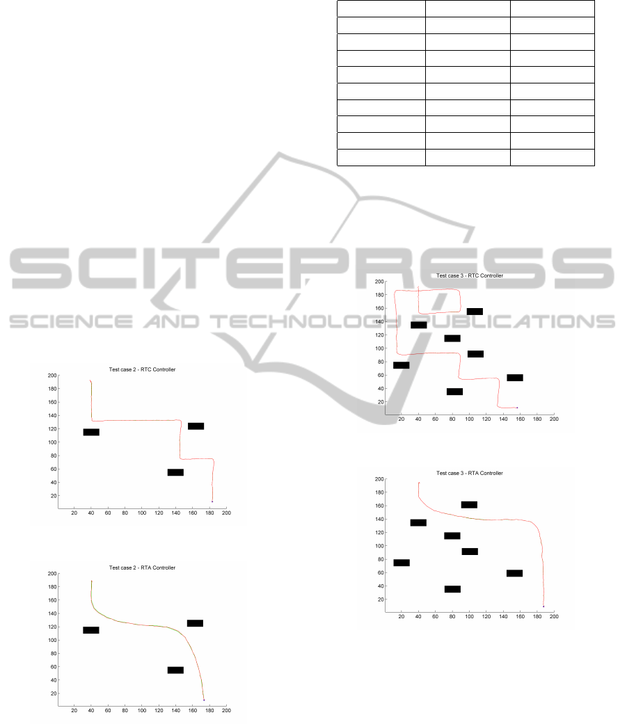
5.3 Test Case 2
In this test case, there are seven obstacles. The differ-
ence between the path of the robot with RTC and RTA
is appreciably in figures 4 and 5. With the FIC advice,
Table 2: Results from test case 1.
Algorithm RTC RTA
Environment I.3.r.sta.nslo I.3.r.sta.nslo
SL1 18.34 27.59
SL2 13.73 16.84
SL3 1.16 0.73
SD 12.94 16.42
PL 321.6 259.94
Tt 27.61 18.56
Cp 234 197
TBe 26.1 349.6
the robot reduces its chances of collision and thus im-
proves its security metrics. Clearly, if SM1, SM2 and
SM3 have high values (see Table 3), the robot moves
through a much safer route because it is far from the
obstacles.
Figure 4: Test case 2 - Path with the RTC controller.
Figure 5: Test case 2 - Path with the FIC advice.
6 RESULTS ANALYSIS
In this section the results presented are analyzed in
order to evaluate the efficiency of the combination of
metrics and indicators as a common standpoint for
comparison of the tests.
In order to obtain statistical data to compare both
algorithms, four sets of fifteen tests each were per-
formed. For each case, a table showing the results for
both, RTC and RTA algorithms was made. Each table
PerformanceEvaluationforAutonomousMobileRobots
369
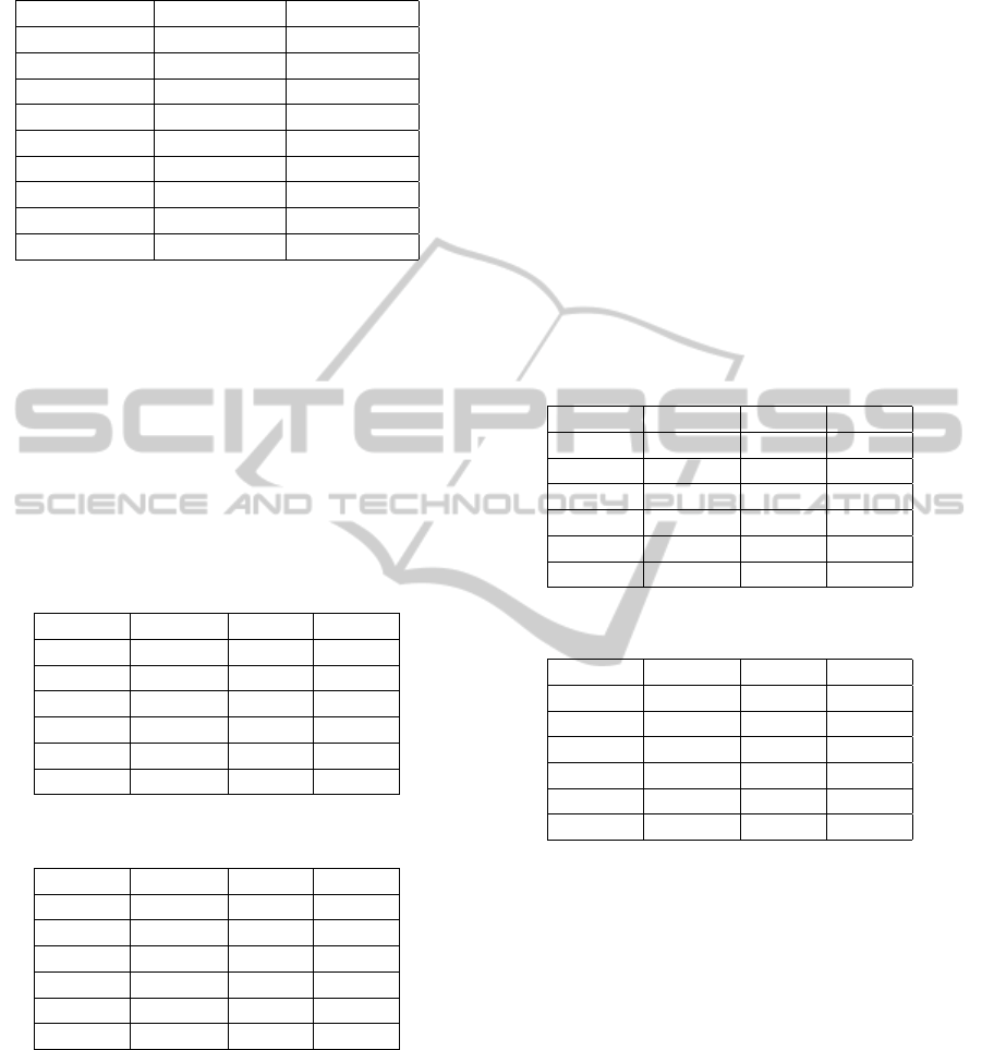
Table 3: Results from test case 2.
Algorithm RTC RTA
Environment I.7.r.sta.nslo I.7.r.sta.nslo
SL1 12.87 19.74
SL2 12.17 17.52
SL3 1.16 0.73
SD 11.68 17.24
PL 507.8 294.46
Tt 46.71 21.03
Cp 284 217
TBe 37.64 318.44
shows the metrics results for the fifteen tests carried
out in each case.
6.1 Results with Two Obstacles
This test case has two obstacles. The path length with
RTA is again shorter than the path followed by the
robot with the RTC algorithm. Below are the numeric
results for both of them in Tables 4 and 5. The envi-
ronment categorization is: I.2.r.sta.nslo.
Table 4: Results for RTC - 2 obstacles.
Statistic Average Min. Max.
SL1 19,96 14,9 19,32
SL2 13,67 12,05 15,43
SL3 1,16 1,16 1,16
Pl 602 572,95 628,72
Tt 53 50,95 54,9
TBe 33,3 30,11 37,5
Table 5: Results for RTA - 2 obstacles.
Statistic Average Min. Max.
SL1 27,74 26,37 28,98
SL2 21,82 20,03 23,64
SL3 0,78 0,78 0,78
Pl 244,48 230,88 252,51
Tt 17,44 16,49 18,03
TBe 381,22 369,41 391,06
As can be observed, the distance traveled by the
robot with RTA is much shorter than the distance trav-
eled with the RTC algorithm. There is also a notable
difference in the time that travels lasted on average
with both algorithms.
From data in Tables 4 and 5, and taking into ac-
count the security metrics (SL1, SL2 and SL3), the
RTA algorithm, performed more safer routes. The
average of SL2 for RTC is 13,67 (centimeters) and
the average for RTA is 21,82 (centimeters). From this
perspective RTA seems to be a more efficient to avoid
obstacles at a greater distance.
Taking into account the TBe values, RTA is a
1331,02 % more efficient performing smooth curves.
The average value of the SL3 metric, 1,16 (seconds)
for RTC and 0,78 (seconds) for RTA, indicates that the
RTC algorithm takes more than the RTA algorithm in
avoiding obstacles.
6.2 Results with Three Obstacles
These tests are similar to the previous ones. Below
are the numeric results when the number of obstacles
to be avoided is three. Data is shown in Tables 6 and
7. The environment categorization is: I.3.r.sta.nslo.
Table 6: Results for RTC - 3 obstacles.
Statistic Average Min. Max.
SL1 18,43 17,35 19,54
SL2 14,46 12,82 15,88
SL3 1,81 1,72 1,87
Pl 459,96 417,43 489,44
Tt 42,76 39,81 44,96
TBe 42,04 37,85 48,2
Table 7: Results for RTA - 3 obstacles.
Statistic Average Min. Max.
SL1 24,25 19,87 26,63
SL2 17,13 14,75 19,28
SL3 0,69 0,53 0,79
Pl 249,15 212,02 270,51
Tt 17,92 16,14 19,32
TBe 427,3 417 443,22
As can be observed from data, RTA is a 916,54 %
more efficient performing smooth curves. This is so
because the TBe metric has a better value. The av-
erage value of the SL1 metric indicates that the RTA
algorithm is 31,58 % more efficient than the RTC al-
gorithm moving further away from the obstacles in
the path of the robot.
The average value of the SL3 metric, 1,81 (sec-
onds) for RTC and 0,69 (seconds) for RTA, indicates
that the RTC algorithm takes more than twice the RTA
algorithm in avoiding obstacles.
It can also be observed that the RTA algorithm
uses fewer control periods and thus less time to get
to the target. The RTC algorithm makes a much
smoother path, saving of energy and making less ef-
fort of the mechanical structure of the robot.
ICAART2013-InternationalConferenceonAgentsandArtificialIntelligence
370

7 CONCLUSIONS
Performance metrics are very important for secure
comparison of several types of algorithms and meth-
ods for autonomous mobile robot navigation. There is
a need to have a standard for environment and robot
description in order to reproduce and compare the
complexity of the problem.
From the tests, it can be said that the intelligent al-
gorithm (FIC) is considerably different from the reac-
tive algorithm. It significantly improves the security
settings, and reaches the goal in less time. RTA uses
the RTC for real time navigation, and provides advice
using an intelligent system based on consciousness,
allowing the robot to better planning the route from
this perspective.
All the comparisons between both controllers
(with and without consciousness) are based on a stan-
dardized description of them and a common set of in-
dicators are defined.
8 FUTURE WORK
It remains pending to test performance using new
metrics and to extend the environment categoriza-
tion system covering further characteristics of in-
door/outdoor and dynamic obstacles.
REFERENCES
Ala’ Qadi, Goddard, S. J. H. F. S. (2005). A performance
and schedulability analysis of an autonomous mobile
robot. In ECRTS.
Bagnell, J.A., B. D. S. D. S. B. S. A. (2010). Learning for
autonomous navigation. In IEEE RAS Magazine.
C. Eberst, M. and Christensen, H. (2000). Vision-based
door-traversal for autonomous mobile robots. In In-
ternational Conference on Intelligent Robots and Sys-
tems. IEEE/ RSJ.
D. Lecking, O. and Wagner, B. (2008). Localization in a
wide range of industrial environments using relative
3d ceiling features. In IEEE International Conference
on ETFA. IEEE.
D. Lopez De Luise, G. B. and Franklin, S. (2011). Robot
localization using consciousness. Journal of Pattern
Recognition Research.
G. Cielniak, A. Treptow, T. D. (2005). Quantitative per-
formance evaluation of a people tracking system on a
mobile robot. In Proceedings of the European Confer-
ence on Mobile Robots (ECMR). ECMR.
J. L. Posadas, J. L. Poza, J. E. S. G. B. and Blanes, F.
(2008). The blackboard model of problem solving
and the evolution of blackboard architectures. In En-
gineering Applications of Artificial Intelligence. AIM.
Jacak, W. (2002). Intelligent Robotic Systems - Design,
Planning and Control. Kluwer Academic Publishers,
New York, 1st edition.
Jipp, M., K. S. W. M. B. E. (2010). Comparative perfor-
mance assessment of path-planning for autonomous
mobile robots using structured intelligence. In IEEE
CCA.
Mu
˜
noz Ceballos, N.D., V. J. L. O. N. (2010). Quantitative
performance metrics for mobile robots navigation. In
INTECH.
Mu
˜
noz Ceballos, N.D., V. J. O. N. (2007). Performance
metrics for robot navigation. In CERMA.
N. Biedma, D. Trejo, D. L. D. L. L. R. G. B. and Isoba,
L. (2011). Consciousness for robot controller: Au-
tonomous mobile robot adaptation. In ASAI.
Nii, H. P. (1986). Agent-based distributed architecture for
mobile robot control. In The AI Magazine. AIM.
Rohrmuller, F., L. G. W. D. B. M. (2009). System interde-
pendence analysis for autonomous mobile robots. In
IROS.
S. Kolski, D. Ferguson, M. B. and Siegwart, R. (2006). Au-
tonomous driving in structured and unstructured en-
vironments. In IEEE Intelligent Vehicles Symposium.
IEEE.
Siegwart, R. and Nourbakhsh, I. (2004). Introduction to
Autonomous Mobile Robots. MIT Press, London, 1st
edition.
PerformanceEvaluationforAutonomousMobileRobots
371
