
Automatic Geometric Projector Calibration
Application to a 3D Real-time Visual Feedback
Radhwan Ben Madhkour, Matei Mancas and Bernard Gosselin
TCTS Lab, University of Mons, 31 Boulevard Dolez, B-7000, Mons, Belgium
Keywords:
RGBD Camera, Structured Light, Geometric Calibration, Depth Map.
Abstract:
In this paper, we present a fully automatic method for the geometric calibration of a video projector. The
approach is based on the Heikkila’s camera calibration algorithm. It combines Gray coded structured light
patterns projection and a RGBD camera. Any projection surface can be used. Intrinsic and extrinsic parameters
are computed without a scale factor uncertainty and any prior knowledge about the projector and the projection
surface. While the structured light provides pixel to pixel correspondences between the projector and the
camera, the depth map provides the 3D coordinates of the projected points. Couples of pixel coordinates
and their corresponding 3D coordinates are established and used as input for the Heikkila’s algorithm. The
projector calibration is used as a basis to augment the scene with information from the RGBD camera in
real-time.
1 INTRODUCTION
For a long time, video projectors have been reduced
to a very classical use: projection on a planar screen
with the projector located in front. The homography
applied on the projected image has enabled to change
the projector but the screen is still a planar surface.
With structured light scanning, projection on complex
surfaces can be performed (Tardif et al., 2003) but the
correction is perfect from only one point of vue: the
camera. Furthermore, if any object moves, the pro-
cess has to be restarted again.
With the rise of intelligent TV and social gaming,
most of the applications need to provide a visual feed-
back to the user. Microsoft’s Kinect sensor allows to
track people easily and to develop intuitive human to
computer interactions (Harrison et al., 2011). Track-
ing moving objects or people is easier (Bradski and
Kaehler, 2008; OpenNI, 2010; Kalal et al., 2010) but
to project on them, a full geometric calibration of the
projector is required. The need for an easy-to-use pro-
jector calibration is growing.
Multiple methods for projector calibration have
already been proposed. Audet and Okutomi (Audet
and Okutomi, 2009) method provides a good way to
calibrate the intrinsic parameters of the projector but it
does not solve the problem of the extrinsic calibration.
The method uses a planar board to calibrate a camera
and a projector at the same time . If the projector is
not close to the camera, it is difficult to project on the
board and in the same time, put the board in a good
position for the camera detection. A solution is to in-
crease the size of the board but the method become
less user-friendly.
In (Ashdown and Sato, 2005; Audet and Cooper-
stock, 2007; Griesser and Van Gool, 2006), the pro-
jector calibration is done in two step. The camera is
calibrated first and the projector afterwards. More-
over, the process is not fully automatic as the user has
to move a board to get different views. Finally, the
extrinsic calibration between the camera and the pro-
jector requires a planar surface.
Raij and Pollefeys (Raij and Pollefeys, 2004)
proposed an auto-calibration method for projector-
camera system but it requires planar surfaces. Drareni
et al.(Drareni et al., 2009) developed an automatic
method for the geometric calibration of multiple pro-
jectors using an uncalibrated camera. However, the
proposed method needs a planar projection surface to
realise the calibration.
In (Li et al., 2008), the authors proposed a method
using structured light (Salvi et al., 2004). This method
needs a planar board with known points for the system
calibration. Furthermore, multiple views of the board
in different positions are needed and the structured
light has to be performed for each view. In (Yamazaki
et al., 2011), Yamazaki et al. presented a method for
the geometric calibration of a video projector using
420
Ben Madhkour R., Mancas M. and Gosselin B..
Automatic Geometric Projector Calibration - Application to a 3D Real-time Visual Feedback.
DOI: 10.5220/0004304604200424
In Proceedings of the International Conference on Computer Vision Theory and Applications (VISAPP-2013), pages 420-424
ISBN: 978-989-8565-48-8
Copyright
c
2013 SCITEPRESS (Science and Technology Publications, Lda.)
an uncalibrated camera and structured light. Never-
theless, the method performs the calibration up to a
scalar factor. Moreover, a prior knoweledge of the
principal point is needed.
In this paper, we propose a fully automatic method
for the geometric calibration of a projector. The pro-
cess is based on the Heikkila’s algorithm (Heikkila,
2000) but it is extended to projector calibration with
the use of the structured light and a RGB-Depth
(RGBD) camera. Unlike the previous methods, the
projection surface itself is used to perform the intrin-
sic and extrinsic calibration. Neither a chess board,
nor a planar projection surface nor any prior know-
eledge are required. The only constraint is that the
calibration surface has to be non-planar. It can be
composed by multiple planes (at least two) or any
complex 3D surface.
The rest of the paper is organised as follows. Sec-
tion 2 describes the projector model. Section 3 in-
troduces the principle of the proposed projector cal-
ibration method. Section 4 gives details about our
implementation, explains the different setup used for
the experiment and gives the results. Section 5 shows
how the real-time visual feedback is implemented. Fi-
nally, Section 6 concludes the work and gives some
perspectives to improve the method.
2 PROJECTOR MODEL
The mathematical model of the projector used in this
paper is the pinhole model (Hartley and Zisserman,
2004). Indeed, a projector is the same as a camera, the
only diffrence being the light ray direction (Kimura
et al., 2007). This model is represented mathemati-
cally by equation 1.
x ∼ P X
world
= K[R|t]X
world
(1)
In this equation, x(u, v, 1) is the pixel position in
the projected image and X
world
(X, Y, Z, 1) is a 3D po-
sition where the pixel x light up. The matrix K is
called the projector calibration matrix. It is defined
by:
K =
f
u
0 u
0
0 f
v
v
0
0 0 1
(2)
where f
u
, f
v
are the focal length in the u and v di-
rection respectively and (u
0
, v
0
), the principal point
coordinates. [R|t] is the pose of the projector and rep-
resents the change of coordinate frame from the world
to projector coordinate. The pinhole model can be ex-
tended in order to take into account the lens distortion.
The reader can find more details in (Hartley and Zis-
serman, 2004; Forsyth and Ponce, 2002).
3 OUR APPROACH
The projector calibration needs multiple couples of
3D coordinates and pixel coordinates. Using the
Zhang algorithm (Zhang, 2000), the constraint of a
planar surface is imposed and multiple views have to
be acquired to achieve a good calibration. To get rid
of the constraint of the planar surface, we propose to
use the Heikkila’s algorithm (Heikkila, 2000). The al-
gorithm is based on the image acquisition of a known
3D patterns (e.g. a white cube with black circular
points).
In our case, we need to calibrate a projector and
the calibration surface is unknown. To solve those is-
sues, we proposed to use the structured light and a
RGBD camera. While the structured light gives pixel
to pixel correspondences between the projector and
the camera, the depth map provides the 3D coordi-
nates of the projected points. Therefore, couples of
3D and pixels coordinates are retrieved. The proposed
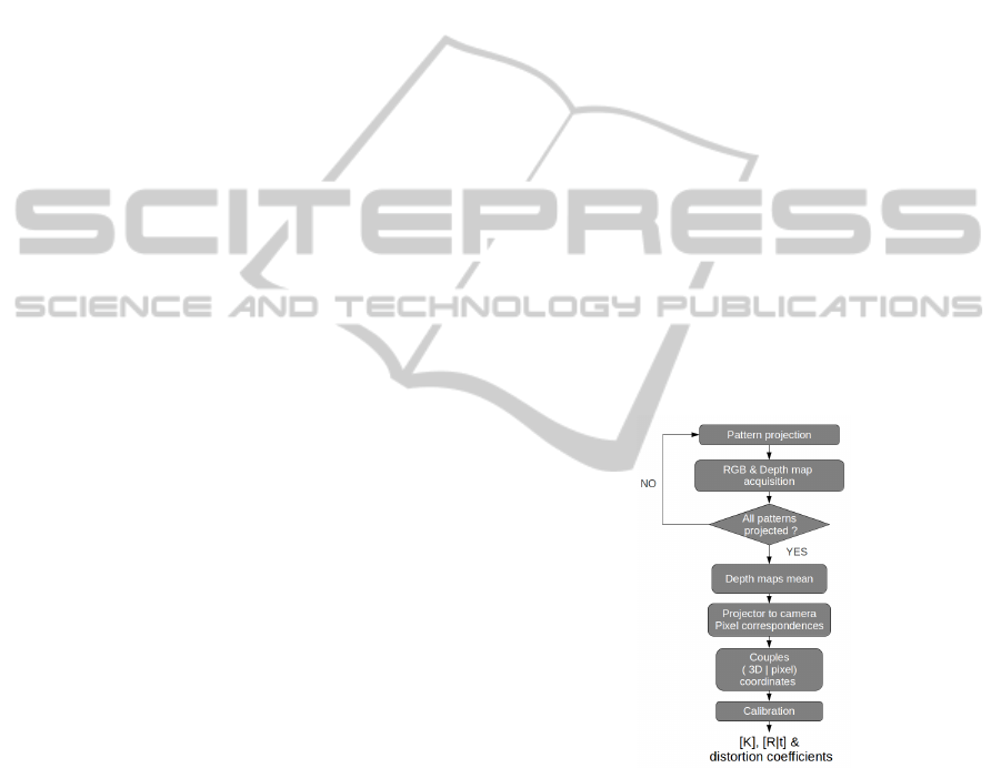
method is represented in figure 1.
Figure 1: Calibration process.
The process is decomposed in different steps:
1. Project the Gray-coded binary patterns
2. Acquire a RGB and a depth map for each pro-
jected pattern
3. Compute the correspondences between the pixel
of the projector and the RGBD camera
4. Average the depth maps
5. Compute the couple of pixel coordinates and 3D
coordinates
6. Apply the Heikkila’s algotrithm
AutomaticGeometricProjectorCalibration-Applicationtoa3DReal-timeVisualFeedback
421
The major advantages of the method are:
Non Planar Surfaces. The combination of the struc-
tured light and the RGBD camera removes the
planar surface constraint.
Simplicity. The RGBD camera gives the 3d coordi-
nates and allows to use classical calibration meth-
ods.
Fully Automated. No user intervention is needed.
No Prior Knowledge Required.
To perform the projector calibration, couples of
pixel coordinates and world coordinates are needed.
This is achieved by using a 3D camera and a struc-
tured light system.
3.1 Structured Light
The structured light is a method for retrieving the
pixel correspondence between a projector and a cam-
era. Our method is based on the Gray coded patterns.
Each pixel of the projector is coded in unique binary
code that is different from the neighbour pixel by one
bit. Each bit of the binary code is processed individu-
ally and a binary image is created per bit, pixels value
being equal to 255 if the bit is equal to 1 and to 0 if the
bit is equal to 0. An example of a set of Gray coded
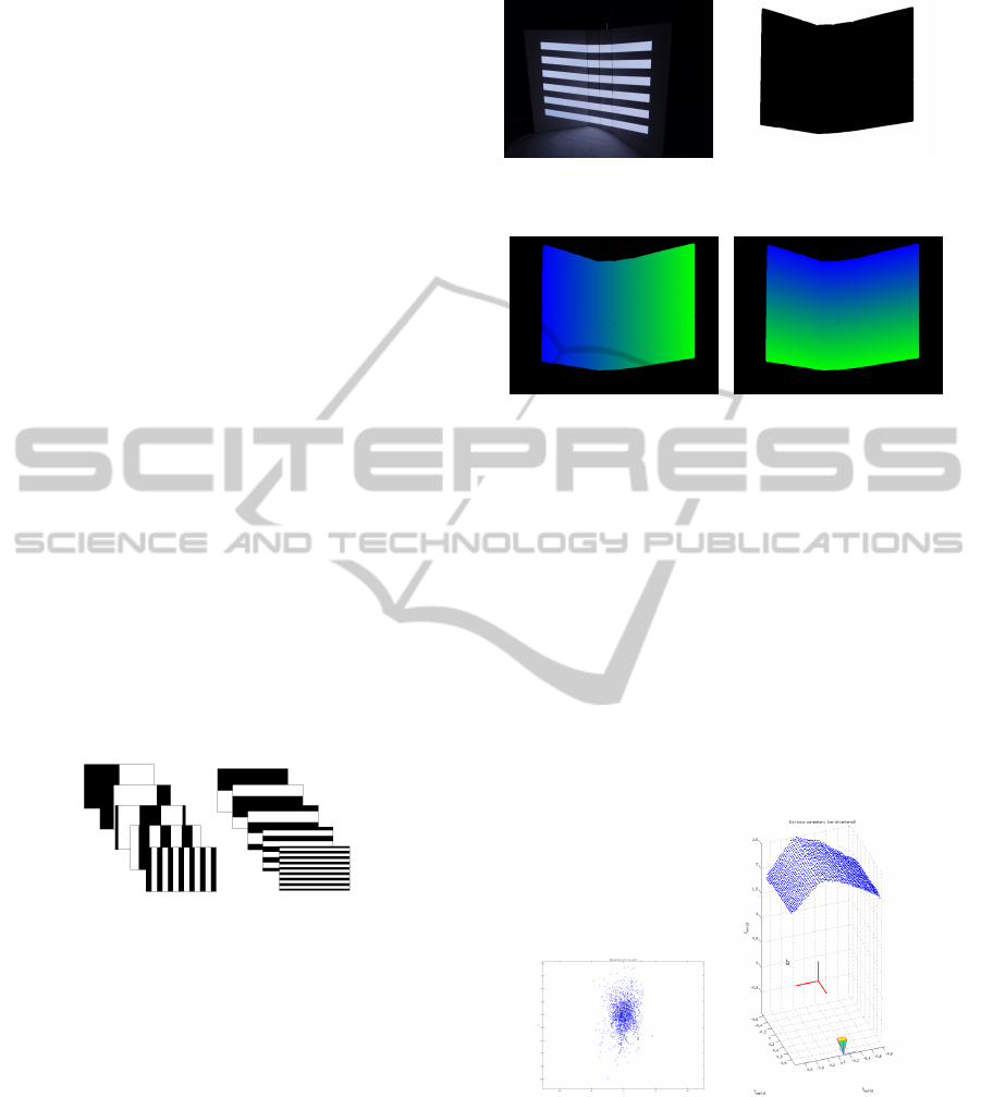
patterns is shown in figure 2. Figure 3 shows the re-
sults of the structured light from the camera point of
view. Figure 3.c is the image of the decoded columns
and figure 3.d, the image of the decoded rows.
Figure 2: Gray-coded binary patterns.
3.2 Depth Camera
The depth camera is a RGBD camera. The RGB part
of the camera allows to acquire images of the pro-
jected patterns while the depth camera is used to get a
3D model of the calibration surface. As both cameras
are calibrated together, a pixel can be associated with
a 3D coordinate. To reduce the inherent error of the
3D measure, a depth map of the projection surface is
acquired each time a pattern is projected. At the end,
all the depth maps are averaged to reduce error.
4 EXPERIMENTS
The structured light is implemented in C++, based on
(a) Projector field of view and
projection surface
(b) Projection area in the camera
image
(c) Decoded pixel columns posi-
tion in the camera view
(d) Decoded pixel rows position
in the camera view
Figure 3: Results of the structured light. Pixel correspon-
dences from projector to camera.
(Lanman and Taubin, 2009). The Camera calibration
toolbox for Matlab from Heikkila (Heikkila, 2000)
and from Bouguet (Bouguet, 2010) provides an im-
plementation of the algorithm.
In our experiments, we used an OPTOMA EX762
projector with a resolution of 1024x768 and a Mi-
crosoft Kinect camera. We performed multiple cali-
bration for different camera positions and for different
zoom of the projector. Example of results are shown
on the figure 4. The average reprojection error is pre-
sented in the table 1.
(a) Reprojection error (b) Side view
Figure 4: Results of the calibration.
Compared to state of the art methods (Yamazaki
et al., 2011; Audet and Okutomi, 2009), the method
provides a higher reprojection error. Those high val-
ues are explained by:
• the error introduced during the structured light
correspondences estimation,
• the error introduced by the RGBD camera,
VISAPP2013-InternationalConferenceonComputerVisionTheoryandApplications
422

Table 1: Average reprojection error RMSE.
Average reprojection error
u v
2.5368 2.3558
• the Heikkila’s algorithm which is less accurate.
Indeed, figure 5 shows that projecting on multi-
ple planes, the pixel of the projector does not appear
on a straight line. Therefore, the pixel coordinates
used for the calibration are biased by the error intro-
duced by the structured light method. As the projector
has a higher resolution than the camera and the pro-
jected image occupies a small part of the camera im-
age, an interpolation is done to get subpixel resolution
in the camera coordinates and this process introduces
error. Moreover, the 3D coordinate measured by the
RGBD camera are also affected by an error. Finally,
as (Sun and Cooperstock, 2006), Heikkila’s calibra-
tion method is less robust to measurement error than
classical method.
Figure 5: Error introduced by the structured light.
5 REAL-TIME VISUAL
FEEDBACK
To perform the real-time rendering, the projector is
modelled in the virtual world by a perspective projec-
tion called frustum. A frustum describes a pyramid
in which every objects present is rendered (see Fig-
ure 6). It is created using glFrustum() function from
OpenGL. It takes six parameters: near, far, left, right,
top, bottom. The left (right) is the position of the left
(right) plane of the pyramid along the x axis. The top
(bottom) is the position of the top (bottom) plane of
the pyramid along the y axis. Those values are ob-
tained from the K matrix ( f
u
, f
v
, u
0
, v
0
, width and
height). The position and the orientation of the cam-
era are set with gluLookAt().
To take into account the lens distortion, the ren-
dering result is set in a texture. The position of each
pixel is modified according to the distortion equation
Figure 6: Perspective projection defined with glFrustum()
(Opengl et al., 2007).
(a)
(b)
Figure 7: Results of the structured light. Pixel correspon-
dences from projector to camera.
(Bradski and Kaehler, 2008).
indent Figure 7 shows the reprojection of a 3D track-
ing information from OpenNI. On this figure, we can
see that the red blob projection follows the user in
real-time regardless the user position.
6 CONCLUSIONS AND FUTURE
WORKS
We have described an original method for the geo-
metric calibration of a projector and applied this new
method to real-time rendering. The proposed method
has multiple advantages.
First, the planar surface constraint introduced
by most of the state of the art techniques is re-
moved by the combination of the Heikkila’s algorithm
(Heikkila, 2000), the structured light and the RGBD
camera. The RGBD camera simplifies the calibra-
tion process, thanks to the depth map. In the same
time, the RGB captor allows to acquire images of the
projected Gray coded patterns and then, to calculate
the projector to camera pixel correspondences. With
this combination, the calibration can be performed on
any complex surface. Second, the method is fully au-
AutomaticGeometricProjectorCalibration-Applicationtoa3DReal-timeVisualFeedback
423

tomated and does not require any user intervention.
Third, no prior knowledge about the projection sur-
face and the projector are needed to achieve the cali-
bration.
Nevertheless, our implementation requires some
improvements. The current projector to camera cor-
respondences computation introduces errors. A better
interpolation method has to be implemented.
ACKNOWLEDGEMENTS
This work has been supported by the numediart re-
search project, funded by Rgion Wallonne, Belgium
(grant N 716631).
REFERENCES
Ashdown, M. and Sato, Y. (2005). Steerable projector cal-
ibration. In Proceedings of the 2005 IEEE Computer
Society Conference on Computer Vision and Pattern
Recognition (CVPR’05) - Workshops (Procams 2005).
IEEE Computer Society.
Audet, S. and Cooperstock, J. R. (2007). Shadow removal
in front projection environments using object tracking.
In Proceedings of the 2007 IEEE Computer Society
Conference on Computer Vision and Pattern Recogni-
tion (CVPR’07) - Workshops (Procams 2007). IEEE
Computer Society.
Audet, S. and Okutomi, M. (2009). A user-friendly method
to geometrically calibrate projector-camera systems.
Computer Vision and Pattern Recognition Workshop,
0:47–54.
Bouguet, J.-Y. (2010). Camera calibration toolbox for mat-
lab.
Bradski, G. and Kaehler, A. (2008). Learning OpenCV:
Computer Vision with the OpenCV Library. O’Reilly.
Drareni, J., Roy, S., and Sturm, P. (2009). Geometric video
projector auto-calibration. In Proceedings of the 2009
IEEE Computer Society Conference on Computer Vi-
sion and Pattern Recognition (CVPR’09) - Workshops
(Procams 2009). IEEE Computer Society.
Forsyth, D. and Ponce, J. (2002). Computer Vision: A Mod-
ern Approach. Prentice Hall Professional Technical
Reference.
Griesser, A. and Van Gool, L. (2006). Automatic interac-
tive calibration of multi-projector-camera systems. In
Proceedings of the 2007 IEEE Computer Society Con-
ference on Computer Vision and Pattern Recognition
(CVPR’06) - Workshops (Procams 2006). IEEE Com-
puter Society.
Harrison, C., Benko, H., and Wilson, A. D. (2011). Om-
nitouch: wearable multitouch interaction everywhere.
In Proceedings of the 24th annual ACM symposium
on User interface software and technology (UIST’11),
pages 441–450. ACM.
Hartley, R. and Zisserman, A. (2004). Multiple view geom-
etry in computer vision. Cambridge University Press.
Heikkila, J. (2000). Geometric camera calibration using
circular control points. IEEE Transactions on Pat-
tern Analysis and Machine Intelligence, 22(10):1066–
1077.
Kalal, Z., Matas, J., and Mikolajczyk, K. (2010). P-N
Learning: Bootstrapping Binary Classifiers by Struc-
tural Constraints. Conference on Computer Vision and
Pattern Recognition.
Kimura, M., Mochimaru, M., and Kanade, T. (2007). Pro-
jector calibration using arbitrary planes and calibrated
camera. In Proceedings of the 2007 IEEE Computer
Society Conference on Computer Vision and Pattern
Recognition (CVPR’07), pages 1–2. IEEE Computer
Society.
Lanman, D. and Taubin, G. (2009). Build your own 3d scan-
ner: 3d photograhy for beginners. In SIGGRAPH ’09:
ACM SIGGRAPH 2009 courses, pages 1–87, New
York, NY, USA. ACM.
Li, Z., Shi, Y., Wang, C., and Wang, Y. (2008). Accurate
calibration method for a structured light system. Op-
tical Engineering, 47(5):053604.
Opengl, Shreiner, D., Woo, M., Neider, J., and Davis, T.
(2007). OpenGL(R) Programming Guide : The Offi-
cial Guide to Learning OpenGL(R), Version 2.1 (6th
Edition). Addison-Wesley Professional.
OpenNI (2010). Openni user guide. Last viewed 19-01-
2011 11:32.
Raij, A. and Pollefeys, M. (2004). Auto-calibration of
multi-projector display walls. In Proceedings of the
Pattern Recognition, 17th International Conference
on (ICPR’04), pages 14–17. IEEE Computer Society.
Salvi, J., Pags, J., and Batlle, J. (2004). Pattern codifica-
tion strategies in structured light systems. PATTERN
RECOGNITION, 37(4):827–849.
Sun, W. and Cooperstock, R. (2006). An empirical evalu-
ation of factors influencing camera calibration accu-
racy using three publicly available techniques. Mach.
Vision Appl., 17(1):51–67.
Tardif, J. P., Roy, S., and Trudeau, M. (2003). Multi-
projectors for arbitrary surfaces without explicit cal-
ibration nor reconstruction. In Proceedings of the
Fourth International Conference on 3-D Digital Imag-
ing and Modeling, 2003. (3DIM 2003), pages 217–
224.
Yamazaki, S., Mochimaru, M., and Kanade, T. (2011). Si-
multaneous self-calibration of a projector and a cam-
era using structured light. In Proceedings of the 2011
IEEE Computer Society Conference on Computer Vi-
sion and Pattern Recognition (CVPR’11) - Workshops
(Procams 2011), pages 67–74. IEEE Computer Soci-
ety.
Zhang, Z. (2000). A flexible new technique for camera cal-
ibration. IEEE Transactions on Pattern Analysis and
Machine Intelligence, 22(11):1330–1334.
VISAPP2013-InternationalConferenceonComputerVisionTheoryandApplications
424
