
Spatial Image Display using Double-sided Lenticular or Fly’s Eye
Lens Sheets
Naoki Kira and Kazuhisa Yanaka
Kanagawa Institute of Technology, 1030 Shimo-ogino, Atsugi-shi, Kanagawa-ken, 243–0292, Japan
Keywords: Spatial Image Display, Lenticular Lens, Fry’s Eye Lens, Floating Image.
Abstract: In this paper, a novel spatial image display system is described in which the 3D image of a real object is
displayed as if it were floating at a position considerably distant from the screen. In our system, double-
sided lenticular or fly’s eye lens sheets are used. The light rays emitted from a point on the object are
refracted by the double-sided lenses sheets and meet together in the space. Therefore a real image that
appears to be floating in the air is formed. Since our system can be produced with only a single material like
transparent plastic and no corner mirrors are necessary, it is suitable for mass-production with metal molds,
and therefore, it is much more inexpensive than existing technologies.
1 INTRODUCTION
Autostereoscopic display systems that use a parallax
barrier, a lenticular lens, or a fly’s eye lens have
already been widely used in various fields and uses,
such as for 3D digital photo frames, a 3D portable
game machine, etc. In some of these systems, a flat
panel display such as an LCD is covered with a
parallax barrier or a lens sheet (Yanaka et al., 2009);
(Kira et al., 2012). However, in such systems, a 3D
image is usually displayed at a position near the
screen since the degree of pop out is not large. The
3D image becomes blurred when it is formed far
away from the display mainly because the pixel size
of the LCD is not small enough, and hence, the
density of the rays becomes coarse rapidly when the
rays become distant from the screen.
In contrast, there is a somewhat similar but
essentially different technology called “spatial image
display” in which a 3D image of a real object is
displayed as if it were floating at a position
considerably distant from the screen. Basically, it is
a passive device consisting of optical components
such as lenses and mirrors only.
2 SPATIAL IMAGE DISPLAY
In a spatial image display, a real object can be used
as the object to be displayed, and users perceive that
the object is floating in the air because a real image
of the object is in front of them.
However, caution is required to prevent the
reversal of depth. To prevent this reversal, an LCD
can be used as the real object. The real image
displayed on the LCD is visible in the air, and
reversal of depth does not occur since the LCD
screen is two-dimensional in nature.
Therefore, this kind of technology is suitable for
making use of the space where the virtual space and
real space overlap in AR or MR or for attracting the
attention of people with digital signage.
Various systems related to this system are also
known. For example, it has been known for many
years that a real image displayed with one big
convex lens can float images of 3D objects in the air.
Here, the convex lens can be substituted by a
concave mirror or a Fresnel lens. Recently, a system
that uses a Fresnel mirror instead of a convex lens
was proposed (Yanaka and Yoda, 2011); (Yanaka et
al., 2012).
Systems that use a special optical component
such as an array of corner reflectors have also been
proposed. A system that uses a Transmissive Mirror
Device (TMD), which is a two-dimensional array of
micro dihedral corner reflectors, was developed by
the National Institute of Information and
Communications Technology (NICT) in Japan
(Maekawa, 2009.). The principle of Askanet’s Aerial
Imaging Plate
TM
(Asukanet, 2012) is similar to it,
but their manufacturing process is considerably
425
Kira N. and Yanaka K..
Spatial Image Display using Double-sided Lenticular or Fly’s Eye Lens Sheets.
DOI: 10.5220/0004345504250428
In Proceedings of the International Conference on Computer Vision Theory and Applications (VISAPP-2013), pages 425-428
ISBN: 978-989-8565-48-8
Copyright
c
2013 SCITEPRESS (Science and Technology Publications, Lda.)
different. In both cases, however, the manufacturing
cost is very high because it is currently difficult to
make many minute mirrors with high precision.
Therefore, we propose a novel and considerably
inexpensive system in which no corner reflectors are
used.
3 METHOD
We developed a system in which an image is
displayed as if it were floating in the air by using a
double-sided lenticular lens sheet or fly’s eye lens
sheet whose thickness is approximately twice the
focal length of the tiny cylindrical or convex lenses
on both sides of the sheet.
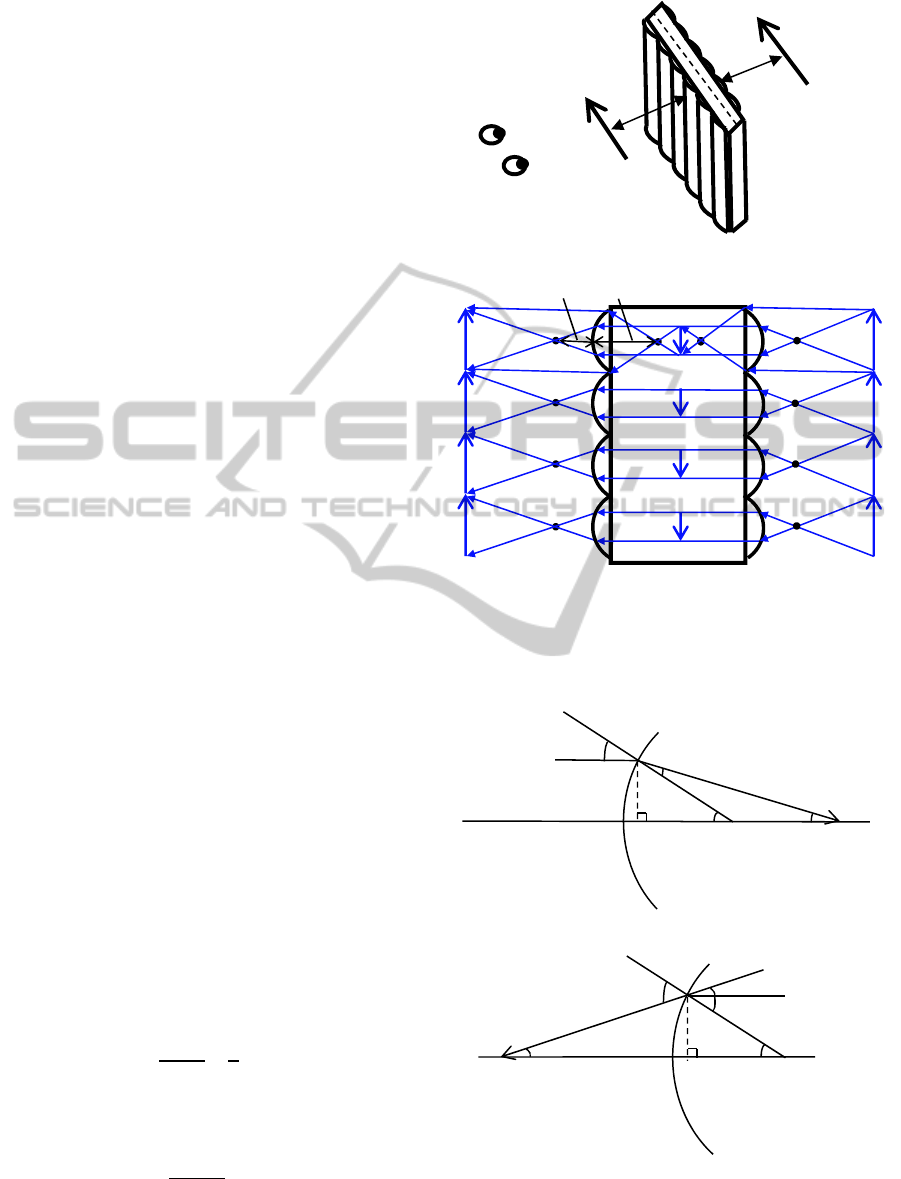
Figure 1 (a) shows a perspective view of our
system. An object is put on one side of the double-
sided lenticular lens sheet. When the object is
observed from the other side, it appears as if it were
floating. Figure 1 (b) shows how light rays pass in
and around the lens sheet. The light emitted from a
point on the object is refracted by the cylindrical
lenses on the other side, and a real image of the
object is formed around the focal point, which is
approximately at the center of the lenticular lens
sheet. Since there is no diffuser there, the rays go
through the real image without being diffused, and
they are refracted by the cylindrical lenses on this
side of the lens sheet. The refracted rays meet
together in the space. Therefore a real image that
appears to be floating in the air is formed.
Figures 2 (a) and (b) show the relation between a
curvature radius and a focal length of a convex piece,
where n denotes the refractive index of the material,
r denotes the curvature radius, f
1
denotes the focal
length inside of the lens, and f
2
denotes the focal
length outside of the lens.
It should be noted that f
1
is larger than f
2
as
follows.
In Fig. 2 (a), the following equality holds.
=
=
(
−
),
and according to Snell’s law,
=
1
Assuming that the material of the lens is acrylic with
n = 1.5,
=
−
=3
(a) Perspective view of our system.
(b) Optical path of incident and refraction light.
Figure 1: Our system’s framework.
Figure 2: Relation between a curvature radius and a focal
length of a convex piece.
3r
Object
Real image
Inverted ima
g
es
2r
Focal point
r
f
1
θ
1
θ
1
-θ
2
θ
2
θ
1
X
Normal line
Incident ray
Refracted ray
Center
(a) Focal length inside lens f
1
f
2
θ
θ
2
θ
1
X
θ
2
-θ
1
Normal line
Incident ray
Refracted
Focal point
Center
(a) Focal length outside lens f
2
Real image
Observer’s eyes
Ob
j
ect
VISAPP2013-InternationalConferenceonComputerVisionTheoryandApplications
426
In Fig. 2 (b), the following equality holds.
=
=
(
−
),
and according to Snell’s law,
=
1
Assuming that the material of the lens is acrylic with
n = 1.5,
=
−
=2
4 EXPERIMENTS AND RESULTS
4.1 Double-Sided Lenticular Lens
Four kinds of single-sided lenticular lenses, shown
in Table 1, were used in the experiments. We made a
double-sided lenticular lens by pasting two single-
sided lenticular lenses back-to-back. When a real
object such as a beckoning cat was put on one side
of the lens and observed from the other side, the
object looked as it if were floating on the observer
side of the lens, as shown in Figure 3.
Figure 3: Double-sided lenticular lens in which two of the
same single-sided lenticular lenses were pasted back-to-
back.
Table1: Specifications of lenticular lenses.
LPI
Thickness
(mm)
Effect
Viewing
angle
(degree)
Viewing
distance
(m)
Material
40
(3D)
2.08 3D 25 1 ~ 4.5 PET-G
40 0.83 2D/3D 49 1 ~ 4.5 Polyester
60
(3D)
1.2 3D 26 0.3 ~ 3 PET-G
60 0.43 2D 74 0.3 ~ 3 PET-A
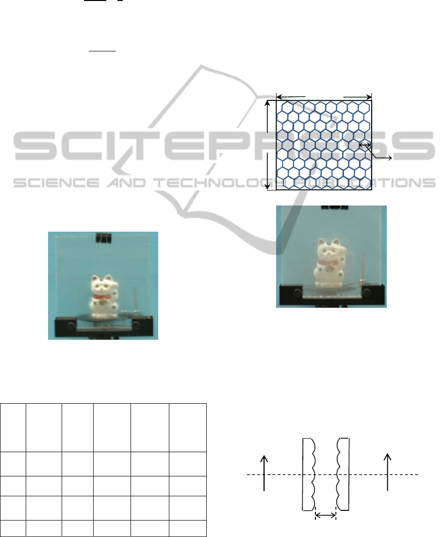
4.2 Double-sided Fly’s Eye Lens
A double-sided fly’s eye lens can be used instead of
a double-sided lenticular lens. In this case, not only
horizontal but also vertical parallax can be obtained.
We conducted experiments by using
commercially available fly’s eye lenses, shown in
Figure 4, and an excellent spatial display could be
produced. In the system that uses a lenticular lens,
stereoscopy might be lost when the head is tilted. In
the system that uses a fly’s eye lens, such worries
are unnecessary.
(a) Specifications of fly’s eye lens.
(b) Experimental result.
Figure 4: Double-sided fly’s eye lens in which two of the
same single-sided fly’s eye lenses were pasted back-to-
back.
4.3 Two Single-sided Lens
It was revealed that two single-sided lens sheets
placed apart at twice the focal length as shown in
Figure 5 can be used together instead of a double-
sided lens sheet.
Figure 5: Alternative way of using two single-sided
lenticular lenses.
152mm
152 mm
1 mm
Focal length =
3.3 mm
Product name: Fresnel technologies 360
2f
Object
Real image
SpatialImageDisplayusingDouble-sidedLenticularorFly'sEyeLensSheets
427
4.4 Combining Lens Sheets
with Different Viewing Angles
It is also possible to combine lens sheets that have
different viewing angles. Figure 6 shows an example
in which a lenticular lens with a viewing angle of 49
degrees and another lenticular lens with a viewing
angle of 25 degrees are pasted back-to-back. In this
case, a clearer 3D image with a large degree of pop
out can be seen when the side with the wide viewing
angle is on the object side and near the object.
Figure 6: Double-sided lenticular lens in which two
different single-sided lenticular lenses were pasted back-
to-back. Object side: 49 degrees, the viewer’s side: 25
degrees.
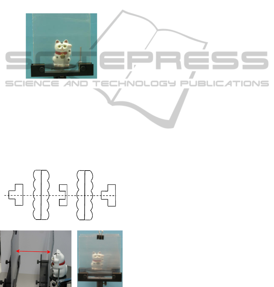
4.5 Depth Correction using Two
Double-sided Lens Sheets
As already stated, depth is reversed in this system.
However, it can be corrected by using two double-
sided lens sheets sequentially as shown in Figures 7
(a) and (b).
(a) Principle of depth correction.
(b) Experimental results.
Figure 7: Depth correction using two double-sided
lenticular lens sheets.
5 CONCLUSIONS
We proposed a novel spatial image display system
that uses relatively inexpensive double-sided
lenticular or fry’s eye lenses, and it was revealed
that a real floating image of a real object can be
displayed, although the depth is reversed. This
problem can be solved by using two double-sided
lens sheets sequentially. However, when the object
is a two-dimensional object such as a PC screen,
reversal of depth does not matter because its real
image made with this equipment is also two-
dimensional. If GUI components such as buttons or
menus are displayed on the PC screen, they will look
like they were floating too. Since the position of a
user’s hand and fingers can be obtained by using
other technologies such as a television camera or the
Microsoft Kinect, the user can do operations such as
pushing a button or moving a cursor without
touching the physical screen. This is no more than
one example among many. This inexpensive device
is considered to hold the power to change human-
machine interfaces.
REFERENCES
Kazuhisa Yanaka, “Integral Photography using Hexagonal
Fly’s Eye Lens and Fractional View”, Proc. of SPIE
Vol. 6803 Stereoscopic Displays and Applications
XIX, San Jose, CA, pp. 68031K-1–68031K-8, 2008.
Satoshi Maekawa, Sandor Markon: Airflow interaction
with floating images. SIGGRAPH ASIA Art Gallery
& Emerging Technologies 2009: 60.
Kazuhisa Yanaka and Masahiko Yoda, “Generation of
Image Perceived as Floating Using Concave Fresnel
Mirror”, ICIPT2011 (17–20 August, Bangkok,
Thailand) pp. 96–101, 2011.
Kazuhisa Yanaka, Masahiko Yoda, and Terumichi Iizuka,
“Floating Integral Photography Using Fresnel Mirror”,
IEEE Virtual Reality 2012 (4–8 March, Orange
County, CA, USA) pp. 135–136, 2012.
Naoki Kira, Kazuhisa Yanaka, Kazutake Uehira: “Integral
Imaging Using Fly's Eye Lens Made with 3D Printer”,
Society for Information Display (SID) Symposium
Digest of Technical Papers, pp.1047-1050, 2012.
Asukanet Co., Ltd.: Aerial Imaging Plate (AIP),
http://aerialimaging.tv/index.html (in Japanese) , 2012.
Object
Real image
Real image
9.5cm
VISAPP2013-InternationalConferenceonComputerVisionTheoryandApplications
428
