
Static Balance based Rescue Robot Navigation Algorithm in Random
Step Environment
Evgeni Magid and Takashi Tsubouchi
Intelligent Robot Laboratory, Department of Intelligent Interaction Technologies, University of Tsukuba, Tsukuba, Japan
Keywords:
Path Planning, USAR, Rescue Robot, Random Step Environment.
Abstract:
To increase safety and extend human rescuers capabilities during a rescue mission a robot is deployed at
a rescue site for exploration purposes. To improve a teleoperated rescue robot performance, we develop an
automatic pilot system which recommends an operator a safe path to a chosen target. We manage the proposed
path from static balance standpoint, based on our previous works. This paper concentrates on path search
algorithm in a simulated 3D debris environment, called Random Step Environment.
1 INTRODUCTION
Rescue robotics goal is to perform tasks in hazardous
or unreachable by humans environments. One par-
ticular domain is urban search and rescue (USAR)
which deals with trappy debris of collapsed construc-
tions, and often buried in unreachable locations vic-
tims. The catastrophe at Fukushima I nuclear power
plant emphasized the indispensability of rescue robots
in high radioactive contamination environments, pre-
venting human personal to perform any task.
During USAR mission a rescue robot explores a
post-disaster debris site, being operated by a human
teleoperator from a safe place outside the site. To de-
crease pressure on a teleoperator in a path planning
stage, we develop a pilot system which helps the op-
erator to select a fairly safe path to a chosen target.
Rough terrain navigation system must be able to
decide if a patch ahead is traversable, or it is an obsta-
cle to be circumnavigated (Ye and Borenstein, 2004).
To estimate a terrain patch, Gennery (Gennery, 1999)
fits planes to the terrain and computes a driving cost,
an accumulating traveled distance, and a probability
that the slope or roughness may be too large to be
traversed. Seraji and Howard (Seraji and Howard,
2002) navigate using terrain local patch roughness,
slope, and discontinuity to represent the traversability.
Kelly (Kelly, 1995) constructs a 2.5D elevation map
and analyzes tip-over, collision, roll and pitch values
along a candidate path. Morphin system (Singh et al.,
2000) maps sensory data into a 25x25 cm cell size
grid, and the goodness of each cell is defined with roll,
pitch, and roughness measures. Cell groups form a
goodness map used for evaluation of a predetermined
candidate arcs set to choose the best trajectory.
The above approaches are suitable for environ-
ments with smooth slopes mainly and are inappro-
priate for typical post-disaster debris scenes with a
significant number of surface discontinuities, which
may result into drastic differences between two con-
sequent robot postures. In this paper we present a path
search algorithm created specially for the navigation
in Random Step Environment (RSE) – a standard-
ized by NIST 3D simulated debris environment (Ja-
coff et al., 2000). The uniqueness of our approach
is the management of a path search for a crawler ve-
hicle in RSE from a balance point of view which is
usually associated with legged locomotion (Zucker
et al., 2010; Belter and Skrzypczynski, 2012). To
make path search feasible we discretize robot move-
ment and state space before the search. The pilot sys-
tem predicts and categorizes a robot posture at each
step of the path with regard to robot static balance.
Next, we apply a modification of Depth-First Search
algorithm for a path search and dynamically construct
a search tree using the rules which we had described
in (Magid et al., 2011).
The rest of the paper is organized as follows. In
Section 2 we describe our system and simulated en-
vironment model. Section 3 presents posture catego-
rization with regard to static stability. Section 4 deals
with transitions between consecutive states. The heart
of the paper is Section 5 which describes the path
search algorithm. Section 7 presents the discussion
of our future work. Finally, we conclude in Section 8.
251
Magid E. and Tsubouchi T..
Static Balance based Rescue Robot Navigation Algorithm in Random Step Environment.
DOI: 10.5220/0004483502510258
In Proceedings of the 10th International Conference on Informatics in Control, Automation and Robotics (ICINCO-2013), pages 251-258
ISBN: 978-989-8565-70-9
Copyright
c
2013 SCITEPRESS (Science and Technology Publications, Lda.)
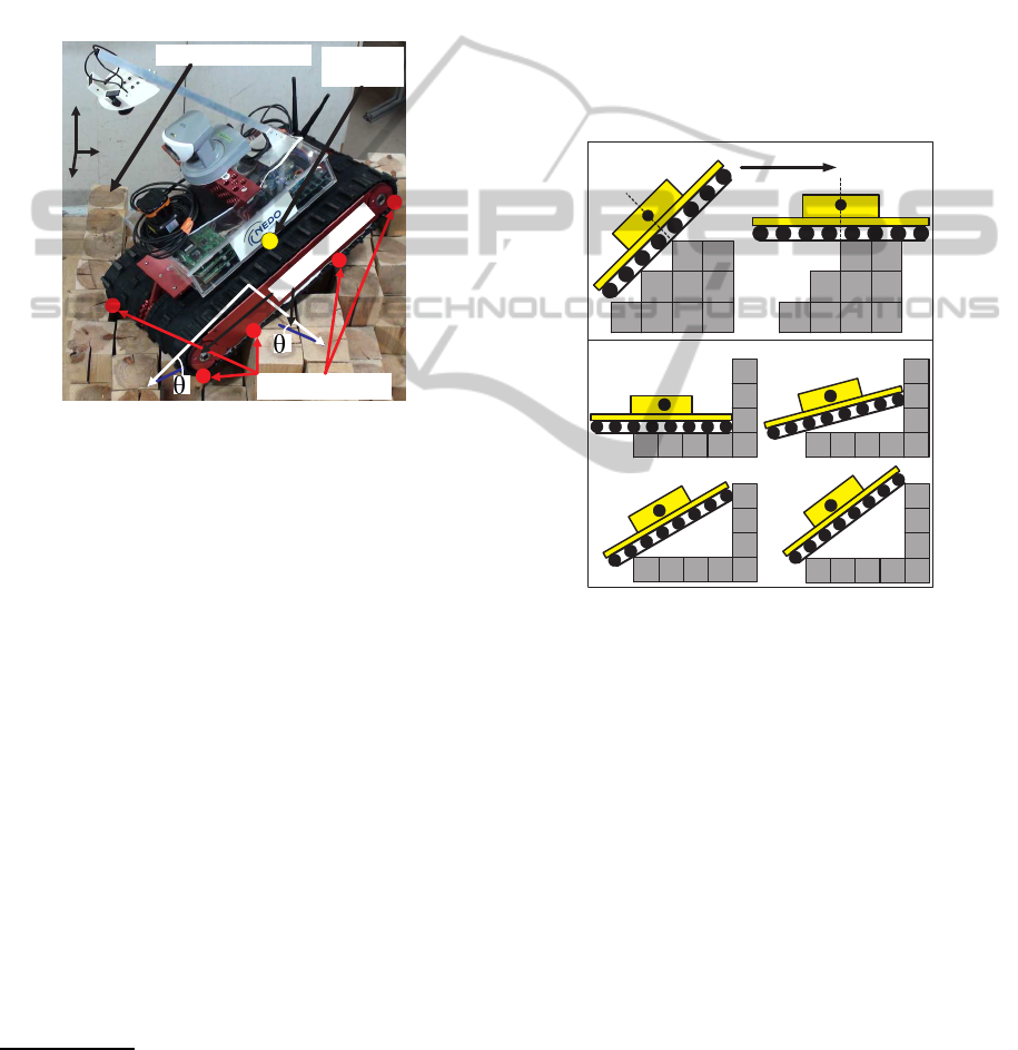
2 SYSTEM SETUP
We assume a tractor-like crawler robot model with a
centroidal center of mass location (CoM) which cor-
responds to the basic configuration of Kenaf robot
without the sub crawlers (Fig.1). Kenaf is developed
by NEDO project (Yoshida et al., 2007), and it is
admitted to have ”the best mobility in the world us-
ing NIST/ASTM rescue robot evaluation field” (Ta-
dokoro, 2008).
XL
YL
Safe CoM
location
Rigid Surface (RSE)
Contact points
Safe inclination
ZG
XG
YG
X
Y
Figure 1: The safety requirements (Conditions A) on the
robot posture while operating in RSE.
For our research we use a Random Step Environ-
ment (RSE) - a standard NIST/ASTM environment
for robot mobility evaluation within RoboCup Res-
cue framework (Jacoff et al., 2011). We assemble
RSE from 85mm × 85mm size wooden blocks of 0,
90, 180, 270, or 360 mm height (Fig.1). We assume
that a small size local map of RSE is always available
to the robot
1
. To reduce the number of search direc-
tions, we discretize the robot movement and the state
space before the search. In (Magid and Tsubouchi,
2010) we showed that discretizing each 85x85 mm
RSE block (XY-coordinates) into 5x5 internal robot
map cells with 17x17 mm size is the best practical
choice for our framework. With this discretization, a
translation step is a one cell length step in the robot
local frame’s axis X
L
direction (Fig.1); a rotation step
is a 5 degrees change in the robot orientation θ, rotat-
ing clockwise (right) or counter clockwise (left). This
way we significantly reduce the possibility of ending
in different from the expected poses when applying
small steps in the control.
1
Our application simulates a locally visible part of the
environment for a given robot posture, sensor range and
global map. For the explanation purposes only we show
full local maps.
3 POSTURE CATEGORIZATION
To guarantee reliable motion, a robot is required to be
stable at each posture. Using a linear projection ap-
proach for static stability estimation (Bretl and Lall,
2008), we define appropriate posture K of the robot
(Fig.1) with Conditions A:
1. Both crawlers contact terrain with no contacts in
the gap between them, thus avoiding getting stuck
2. Exist at least three distinct contact points
3. No slipping/overturning due to surface inclination
4. No overturning due to robot’s CoM displacement
If at least one of Conditions A is not satisfied at pos-
ture K, posture K is not appropriate.
(a)
CoM
CoM
Moving
direction
CoM
CoM
CoM
CoM
(b)
(c) (d)
(e)
(f)
O1
O2
Figure 2: Controlled balance loosing (CBL) at Orange state:
posture changes from O
1
(a) to O
2
(b). M-chain at climbing
up from (c) to (f).
From static stability standpoint we distinguish six
posture types, presented in Table 1. Red is a prohib-
ited posture. Cyan denotes a jump down. Normalized
Energy Stability Margin (NESM) (Hirose et al., 1998)
is applied to distinguish between two statically stable
states: high (Green) or fair quality balance (Yellow).
An unstable Orange posture affords to traverse obsta-
cles with loosing balance twice on a top: at a barrier
edge the robot changes its posture O
1
(Fig.2a) discon-
tinuously and reobtains a balance in a different body
orientation O
2
(Fig.2b) as a result of inertia. This
controlled balance loosing (CBL) state is indispens-
able for the path planning (Magid et al., 2010). Ma-
genta state denotes an ascend/descend on a vertical
RSE slope; we define M-chain as a sequence of Ma-
genta postures (Fig.2d,e) between two stable postures
(Fig.2c,f). The detailed explanations on the posture
categorization could be found in (Magid et al., 2008).
ICINCO2013-10thInternationalConferenceonInformaticsinControl,AutomationandRobotics
252
Table 1: The color labels explanation.
Label Balance quality Technical details
Red (R) The robot turns upside down OR Pitch >
π
4
OR Roll >
π
6
OR
Gets stuck At least one of Conditions A is not satisfied
Orange (O) Controlled balance loosing (CBL) Two optional postures O
1
and O
2
exist
Magenta (M) The robot ascends OR descends Oscillations in posture estimation algorithm
a vertical slope of RSE
Cyan (C) The robot jump down CoM jump between two stable postures < 50mm
Yellow (Y) Fair balance (not (R, O, M or C)) AND (NESM parameter < 1)
Green (G) Good balance (not (R, O, M or C)) AND (NESM parameter ≥ 1)
4 TRANSITIONS BETWEEN
CONFIGURATIONS
To create a search tree, presented in the next sec-
tion, we provide a branch cutting function (BCF)
F(Args) = Res. Args are a current robot configuration
and a local environment map. Res is a set of accessi-
ble within one step configurations, which are at most
three postures: go straight, rotate left or right. BCF
uses color categorization and estimation of a particu-
lar transition feasibility and quality in order to remove
all impossible search directions from the search tree
and to define the cost evaluation function.
To decide on legal transitions between two suc-
cessive states, we use a combination of pitch, roll,
and contact point quality parameter.
2
We built a large
set of RSEs and confirmed experimentally the set of
rules on translational and rotational steps between
two successive postures to estimate particular tran-
sition feasibility (Magid et al., 2011). To obtain a
proper level of the real world approximation, we im-
plemented the rules in our simulator and executed ex-
haustive simulations followed by verification exper-
iments. The loop rules-simulation-experiments was
repeated multiple times: the rules and the thresholds
were updated each time until the correlation between
the three stages became satisfactory. All possible
pairs of postures, connected with a translational or ro-
tational step, were divided into groups using color cat-
egories and pitch/roll/contact parameters. Each group
is labeled as possible, undesirable or prohibited cate-
gory transition with regard to the rules. Within each
of these three categories the quality of individual tran-
sitions may differ significantly, and it is reflected in
path cost function g(v), presented in Section 5.2. A
path is formed mainly with possible category transi-
tions. Undesired transitions have a limited appearance
within the path, while the usage of prohibited ones is
totally prohibited.
2
Depends on the angle between robot crawlers and the
edges of RSE cells and affects the ability to ascend obsta-
cles, to lose balance at CBL, and to descend safely.
5 PATH PLANNING
To find a good path in RSE we create a search tree by
means of our BCF. To speed up the search and provide
a fairly good solution, gaining computational perfor-
mance potentially at the cost of accuracy, heuristic
methods are used (Russel and Norvig, 2002). When
applied for a tree search, a selective at each decision
point heuristic focuses on paths that seem to push
the robot closer to the target configuration rather than
exhaustively exploring all available options. For a
heuristic search algorithm the evaluation function of
node v is defined as f(v) = g(v) + h(v), where cost
g(v) is the actual cost to reach node v from start S, and
heuristics h(v) is the estimated cost of reaching target
T. Next we present the search tree construction, cost
function definition and our search algorithm.
5.1 Search Tree
A naive branching function for each node opens all
three descendant nodes - go straight, turn left/right
(Fig.3a) - and the number of nodes explodes expo-
nentially with search depth D, where D≥dist(S, T) for
a discretized distance between start S and a chosen
within a visible patch of the environment target T.
t
t+1
t+2
t+3
t
t+1
t+2
t+3
(a)
(b)
Figure 3: (a) Naive algorithm search tree (NAT) and (b)
improved tree (IT) for depth D=3. White circle denotes a
translational step, red and blue denote rotation left and right
respectively.
At first we create an improved tree (IT, Fig.3b)
saving one additional node opening at each rotational
StaticBalancebasedRescueRobotNavigationAlgorithminRandomStepEnvironment
253
Table 2: Good translational transitions cost (in points). P
1
and P
2
are the first and the second postures of the pair.
Label P
1
P
2
Motion type g(v)
I G G Flat RSE patch 1
II O G CBL, ascend (A) 10
III G G Uniform ascend (UA) 5
G G Uniform descend (UD) 5
IV O G UA after CBL 12
O G UD after CBL 12
V G O CBL, A 10
VI G O CBL at descend 15
step by prohibiting oscillating rotations: immediately
after a rotation left a rotation right would be useless,
returning the robot to the previous configuration. To
reduce further the number of nodes, BCF F(Args) is
applied to IT and F-tree (FT) is created – the search
tree utilized by our algorithm. At small search depth
D naive algorithm tree (NAT), IT and FT have simi-
lar number of explored nodes, but as D increases, the
difference becomes dramatic (Magid et al., 2011).
5.2 Evaluation Function
Let P
1
and P
2
denote a first (current) and a second
(next) posture of a connected by a single step pair
respectively. At first, color labels of P
1
and P
2
are
calculated, and a transition between P
1
and P
2
is cate-
gorized. For a prohibited transition the node is cut off
from the search tree with the entire branch that origi-
nates at P
1
. Next, for good and undesirable transitions
the step cost of transition P
1
→ P
2
is obtained from
Tables 2–5. A brief description of the transition type
is given in column ”Motion type”, while the detailed
explanations on each transition, including prohibited
ones, could be found in (Magid et al., 2011). Finally,
column ”g(v)” gives the transition cost.
Table 3: Undesirable translational transitions cost (points).
Label P
1
P
2
Motion type g(v)
VII G G CBL miss,descend(D) 15
VIII G G CBL miss, ascend (A) 10
IX G G M-chain miss, D 20
X G G M-chain miss, A 20
XI G G Non-uniform A 40
XII G O CBL, non-uniform D 100
XIII M O M-chain, D
followed by CBL 5000
XIV G G Non-uniform D 100
XV O M CBL followed by
M-chain, A 5000
XXIII M M M-chain, A 10
XXIV M M M-chain, D 10
Table 4: Good rotational transitions cost (points).
Label P
1
P
2
Motion type g(v)
XVI G G Flat patch 5
XVII G G Descending patch (DP) 15
XVIII G G Ascending patch (AP) 20
XIX G G DP with small body
orientation change 30
XX G G AP with small body
orientation change 40
Table 5: Undesirable rotational transitions cost (points).
Label P
1
P
2
Motion type g(v)
XXI M M Slide down 1000
XXII C G Jump down 3000
The transition cost was established empirically
through the experiment observations taking into an
account operational complexity, probability of failure
due to non-zero friction, sliding, power consumption,
etc. The most simple motion is traversing a flat patch
of RSE (I). A uniform ascend/descend of a vertical
slope (III) and rotation on a flat RSE patch (XVI) re-
quire some attention and are more energy consum-
ing. If CBL appears at ascend/descend explicitly
(II,V,VI) or implicitly (VII,VIII), a special attention
of the operator is needed. CBL at descending (VI,VII)
is more dangerous, making such transition to cost a
little more; an explicit appearance of CBL in uniform
ascend/descend (VI) costs somewhere in between.
Transitions XXIII and XXIV denote explicit ascend-
ing and descending M-chains respectively. Missed
M-chains at descend (IX) or ascend (X) mean faster
changes than explicit M-chains and have equal costs:
while a fast descend (sliding down) is more dangerous
for sensors, ascending a vertical wall consumes more
energy and may change robot orientation slightly after
completion. Non-uniform ascend (XI) and descend
(XIV) intend a CBL appearance; descend is less pre-
dictable, as well as an explicit CBL at non-uniform
descend (XII). The rotation step is more intuitive -
the more body orientation changes, the higher it costs.
Also a rotation on a descending slope is easier than
on an ascending. Sliding down (XXI) and jumping
down (XXII) while rotating are rather unpredictable
and thus have high costs in order to avoid their appear-
ances. Finally, two complicated translational transi-
tions XIII and XV receivean extremely high cost, rep-
resenting a sort of ”last chance” for the operator.
For the path planning transitions with cost 1–50
points are mainly used. A number of 100 points cost
transitions may postpone the further path exploration
for a while. Transitions with cost over 1000 points
leave rather small chances for the further exploration
of the current path. Yellow category postures are
treated in the same way as corresponding green pos-
ICINCO2013-10thInternationalConferenceonInformaticsinControl,AutomationandRobotics
254
tures and add 50% penalty to cost g(v). E.g. transla-
tion Y→G (UA) will cost 5+2.5 points, while Y→Y
will cost 1+0.5+0.5 points.
Heuristic for node v is defined as h(v) = St
T
(v, T)
+ K×St
R
(v, T), where St
T
is a number of translation
steps from node v to target T on a straight line, and
St
R
is a number of necessary rotation steps to align
orientation θ at node v configuration with the target
orientation. We varied heuristic functions from the
ones forcing the robot to search within a limited sec-
tor first (i.e. concentrated on keeping direction to T)
with large parameter K to K=0 for distance impor-
tance only. Finally, to ensure that the heuristic func-
tion will be always admissible, we set K=0. Since for
the rescue task it is enough to arrive to the target des-
tination more or less precisely, the orientation is less
important if we converge in the terms of distance.
5.3 Path Search Algorithm
The most famous heuristic search algorithm is proba-
bly A
∗
- a best-first search type algorithm (Hart et al.,
1968) which always finds an existing optimal path but
has exponential time and space requirements. Modi-
fications of A
∗
, like Iterative deepening A
∗
(IDA
∗
), re-
duce space requirements to linear (Korf, 1985), but
unfortunately, all variants of A
∗
at each step select
and expand a most high potential node in terms of
function f(v). Thus, successively expanded nodes v
i
and v
i+1
are not necessarily adjacent. The class of
graph search algorithms, which avoid such undesir-
able jumps, is Depth First Search algorithm (DFS).
DFS (Russel and Norvig, 2002) is the uninformed
search that progresses by expanding the search tree in
depth in the first child node direction until a goal node
or a node without children is reached. In the later case
the search backtracks and returns to the most recent
node it did not finish.
We have chosen DFS algorithm for our applica-
tion since we strongly believe that it would converge
fast to the target if the path exists. However, to signal
that the path does not exist after exploring the entire
tree takes the same time as any other tree search al-
gorithm. Often the search graph is too large for the
entire exploration, and in such cases DFS would suf-
fer from non-termination. Therefore, when the ap-
propriate depth limit is not known in advance, the
search may be performed by iterative deepening, ap-
plying DFS repeatedly with a sequence of increasing
depth limits. In addition, DFS is much easier to in-
tegrate with heuristic methods of choosing a prospec-
tive search direction. We make two improvements to
iterative deepening DFS and call it MDFS-R - a Mod-
ified DFS for Rescue:
• Switch a search direction when the current path
becomes unsatisfactory
• Use heuristics to ensure the preference of a more
promising search direction
5.4 MDFS-R Algorithm
Similarly to DFS, our algorithm at each node of FT
search tree expands 3 (or 2) descendant nodes and
chooses the most prospective descendant direction
with regard to evaluation function f(v) to continue
the exploration of the search tree.
(a)
Leaf
Opened node
Leaf
#1
#2 #4#3
#1
#2
#1
#2
#5 #7#6
#1
#2
#7
#8
#9
#10
Switch condition:
store #10 as Leaf
#1
#2
#7
#8
#9
#5
New branch:
Proceed from
here
Branch
cut off
Prohibited
node
(b)
(c)
(d)
(e)
VSw
Vnew
Figure 4: MDFS-R algorithm search tree with the encoun-
tered nodes distribution to Leaves (green), Open (yellow)
and Prohibit (red) lists.
Figure 4 demonstrates MDFS-R algorithm. We
start at node #1, open and evaluate its 3 children -
Leafs (Fig.4a, green ovals). Nodes can have 1 (Fig.4d,
node #7), 2 (node #9) or 3 (node #1) children. Next,
the node is stored in Open list (yellow ovals). If a
child node is categorized as red during the evalua-
tion, it is cut off from the search tree and stored in
Prohibit list (Fig.4d, red rectangular). Among those
children a most promising in terms of minimal cost
and heuristics g(v)+h(v) node is chosen to continue
the search while others are stored as Leafs (Fig.4b).
This procedure is repeated (Fig.4c) until the target
is reached
3
or a switch condition (explained in the
next paragraph) is triggered (Fig.4d, node #10). The
node, which triggered the switch, is stored as a Leaf
(Fig.4e). The search continues in a different direction
starting at a most promising leaf v
new
(Fig.4e, node
#5), which minimizes the cost function with inflated
heuristic g(v)+10 × h(v). Arrival to a dead end acti-
vates a backtracking mechanism identical to the one
of DFS.
MDFS-R switches the search direction at node v
Sw
in the three following cases:
3
Or returning to the start if the path does not exist
StaticBalancebasedRescueRobotNavigationAlgorithminRandomStepEnvironment
255

1. Path cost g(v) becomes too high: the path be-
came too long or/and contains a large number of un-
desired transitions reflected in its cost. Exceeding
Sw
C
threshold signals that the robot seems to be on
a wrong path and has to change the search direction.
Initially we set Sw
C
= 1.5 × St
T
(S, T), where St
T
(S,
T) is a number of translational steps from Start to Tar-
get. After this switch is triggered, Sw
C
is reset to 1.5
× g(v
new
), where g(v
new
) is the path cost from Start
to the selected leaf v
new
. This switch condition is up-
dated throughout the search after every switch.
2. Significant number of undesired transitions ap-
pears within the path; this threshold is set to Sw
U
=
20. It signals that the path became rather complicated
and a human teleoperator may have difficulties to re-
peat it.
3. The current search direction starts to move the
robot away from the desired target. We set this thresh-
old Sw
H
= 1.5 × St
T
(S, T).
When one of the three target variables exceeds its
threshold, the path becomes undesirable and its fur-
ther exploration is postponed. If all available choices
violate a switch constraint, after choosing the most
promising node the corresponding threshold is in-
creased. While Sw
C
and Sw
U
may only increase dur-
ing the path search, Sw
H
is reset to 1.5 × St
T
(v
new
, T)
after every switch. MDFS-R can switch back to any
of the postponed pathes later.
Each node v of FT search tree contains key in-
formation [x, y, θ], posture information [z, θ
X
, θ
Y
,
NESM, support polygon square, color], pointers to
ancestor node PF(v) and three children nodes - go
straight PS(v), rotate left PL(v) and right PR(v),
heuristic estimation h(v) from v to target T, path cost
g(v) from start S to v, and number of undesired tran-
sitions UN(v) within that path. We maintain 3 lists of
nodes: Opened, Prohibited, and Leaves. Opened list
stores explored nodes with expanded children; they
may be a part of the successful path. Nodes that were
categorized as ”red” are cut off from the tree without
further exploration of the forthcoming branch, stored
in Prohibited list, and do not appear in FT. If after ex-
ploration a leaf was evaluated as leading to a dead
end, it shifts from Opened list into Prohibited list.
Leaves which do not belong to any path yet, are filled
up with internal information and stored in Leaves list
with PS(v)=PL(v)=PR(v)=NULL. When a new node
is just opened its key is verified against Opened, Pro-
hibited, and Leaves lists to prevent multiple explo-
rations.
If during the search one of the three switching
conditions is triggered while comparing h(v) to Sw
H
,
g(v) to Sw
C
, and UN(v) to Sw
U
, the node of the
switch (fig.4d, node #10) is stored in Leaves list and
the current candidate path explorationis postponed. A
better search direction with regard to the three switch
parameters is chosen (node #5) minimizing g(v)+10
× h(v), and a different candidate path exploration be-
gins. If no better node with regard to current Sw
threshold values exists in Leaves list, the violated
threshold(s) is(are) increased as was explained earlier.
When the target is reached, the path is backtracked
through PF(v) pointers.
6 SIMULATION
The search algorithm was implemented in MATLAB
environment. Figures 5 and 6 present two simple ex-
amples which demonstrate MDFS-R behavior in typ-
ical situations. For the demonstration purposes only
we assumed a full knowledge of a large local RSE
patch while usually for a real USAR task the patch
size is significantly smaller. When the obstacle be-
tween S and T is passable but short, or on the contrary,
the obstacle is impassable – the algorithm decides to
get round instead of climbing up (Fig.5). When the
obstacle is passable but very long, or it cannot be cir-
cumvented for some reason, the algorithm chooses to
traverse the obstacle (Fig.6). Each cell of the XYZ-
grid corresponds to RSE cell. The blue rectangular
shows the robot at each distinct posture of the dis-
cretized path and the color dots (placed at the robot’s
CoM) denote static balance category labels.
0
5
10
15
20
25
30
0
5
10
15
20
25
30
0
0.5
1
Start
Tar get
Figure 5: The robot denoted with blue rectangular circum-
vents small size or impassable obstacles.
Avoiding a pole like obstacle (Fig.5) is a rather
trivial task for a human operator, especially under
perfect information simulations. The second task of
crossing a ridge line (Fig.6) doesn’t appear very chal-
lenging as well since there are a large number of
equally good paths to choose from. So these typical
tasks an experienced teleoperator would perform well
without any supporting pilot system.
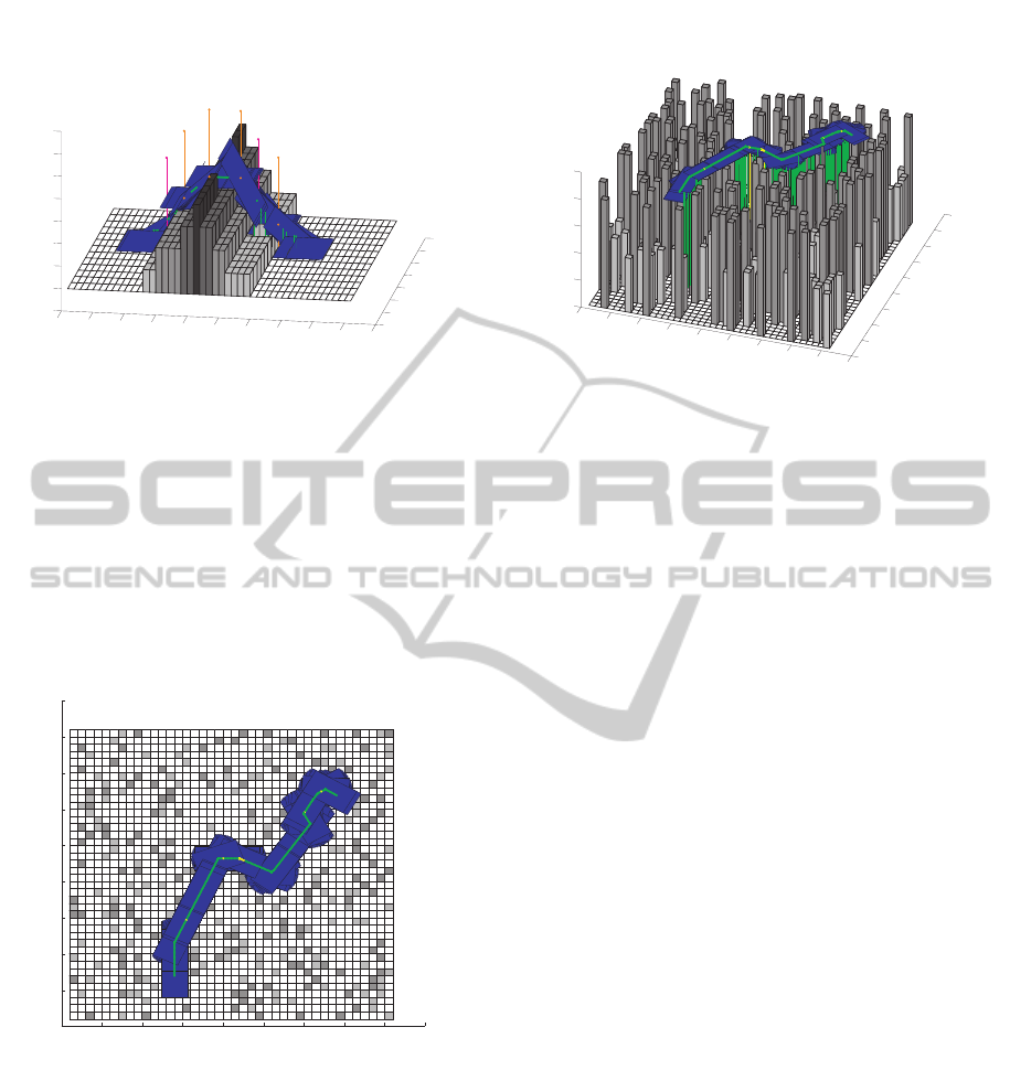
Figures 7 and 8 present the map created with a
random generator and randomly chosen start and tar-
ICINCO2013-10thInternationalConferenceonInformaticsinControl,AutomationandRobotics
256
0
2
4
6
8
10
12
14
0
5
10
15
20
25
30
35
40
45
50
-1
0
1
2
3
4
5
6
7
Tar get
Start
Figure 6: The robot climbs the passable obstacle. The ob-
stacle cells are marked with the grey color: the darkest are
4 units high, the lightest are 1 unit. The 0 high white cells
correspond to free space.
get points. While after a number of trials a human
operator would probably end up with the robot tip-
over, our pilot system succeeded to find a complicated
path in RSE with type I translation and type XVI rota-
tion steps only. Except few fair balance postures (yel-
low dots) within the path, good balance (green dots) is
guaranteed along the path and no changes in pitch and
roll are involved, preserving horizontal orientation of
the robot.
0 5 10 15 20 25 30 35 40 45
0
5
10
15
20
25
30
35
40
45
Start
Tar get
Figure 7: A complicated scenario in the random map (view
from above). The RSE cells have 2 (dark grey), 1 (light
grey), and zero (white) unit height.
7 FUTURE WORK
Due to the nature of debris scenarios, using in some
sense deterministic transitions based on discretized
controls is a strong assumption. The transition be-
tween states may become unreliable due to the kind
of terrain, drift, slippery, etc. As a part of our future
work we are going to model the possibility of ending
in different from the expected poses when applying
0
5
10
15
20
25
30
35
40
45
0
5
10
15
20
25
30
35
40
45
0
0.5
1
1.5
2
2.5
Start
Tar get
Figure 8: The robot succeeds to find a path preserving hor-
izontal orientation along the path.
a control. Next, we plan to compare MDFS-R algo-
rithm effectiveness with a number of existing plan-
ners. While by construction MDFS-R is performing
better then classical BFS, DFS, and A
∗
in terms of
average number of opened nodes, we are interested
to compare MDFS-R and advanced modifications of
A
∗
, e.g. IDA
∗
(Korf, 1985) or ARA
∗
(Likhachev et al.,
2004), using different inflated heuristics.
MDFS-R algorithm is targeted to search a locally
suboptimal path to a target, which satisfies USAR
task, without reconstructing a global map of the en-
vironment, and the possibility that the constructed
search tree would be used once again for the next
stages of USAR mission is relatively small. Yet, if for
some reason the robot will have to return and replan,
some parts of previouslyconstructed search tree could
be reused if we continuously construct and maintain
the global map of the rescue scene.
The presented in this work results strongly depend
on the considered hardware of KENAF robot, but the
proposed approach may be reused at some degree
with a different hardware setup. As a part of our long
term goal we are interested to apply the proposed re-
search framework for the assistant path selection sys-
tem developmentwith several other robotic platforms.
We plan to build system prototypes followed by real
time application development, including global map
construction and sensory input treatment.
8 CONCLUSIONS
In this paper we presented static balance based path
search algorithm in Random Step Environment for a
crawler robot. To make the search feasible, we dis-
cretized robot movement and state space before the
search. Our modification of Depth-First Search al-
StaticBalancebasedRescueRobotNavigationAlgorithminRandomStepEnvironment
257

gorithm, targeting specially for path planning tasks of
USAR scenarios, dynamically constructs a search tree
and provides a fairly safe path to a chosen by the op-
erator target. The simulations showed that while in
simple scenarios an experienced operator can manage
the path planning process easily, our assistant pilot
system is critical in complicated scenarios.
Even though the presented solution deals only
with a static stability of the vehicle and suffers from
a number of drawbacks and limitations like strong as-
sumptions on rigid and stable RSE, absence of slip-
pery and external disturbances, centroidal location of
robot’s CoM, etc., we believe that our unique ap-
proach to the crawler robot path planning from static
stability standpoint makes a significant contribution
to the rescue robotics domain. While the presented
results strongly depend on the considered hardware,
the proposed approach may be reused at some degree
with a different hardware setup. This way we cre-
ated a complete framework which could guide assis-
tant system development for any typical crawler vehi-
cle operating in USAR scenario.
ACKNOWLEDGEMENTS
This work was partially supported by NEDO Project
for Strategic Development of Advanced Robotics Ele-
mental Technologies, High-Speed Search Robot Sys-
tem in Confined Space. Special thanks are extended
to Leave a Nest Co. Ltd., Japan, for the generous fi-
nancial support of this work.
REFERENCES
Belter, D. and Skrzypczynski, P. (2012). Posture optimiza-
tion strategy for a statically stable robot traversing
rough terrain. In IEEE Int. Conf. on Intelligent Robots
and Systems.
Bretl, T. and Lall, S. (2008). Testing static equilibrium for
legged robots. IEEE Trans. on Robotics, 24(4).
Gennery, D. B. (1999). Traversability analysis and path
planning for a planetary rover. Autonomous Robots,
6(2).
Hart, P. E., Nilsson, N. J., and Raphael, B. (1968). A formal
basis for the heuristic determination of minimum cost
paths. IEEE Trans. on Systems Science and Cybernet-
ics, 4(2).
Hirose, S., Tsukagoshi, H., and Yoneda, K. (1998). Nor-
malized energy stability margin: generalized stability
criterion for walking vehicles. In The 1st Int. Conf. on
Climbing and Walking Robots.
Jacoff, A., Messina, E., and Evans, J. (2000). A stan-
dard test course for urban search and rescue robots.
In Performance Metrics for Intelligent Systems Work-
shop’00.
Jacoff, A., Virts, A., and Downs, T. (2011).
RoboCup Rescue Robot League Arenas: Ma-
jor component descriptions. Available online:
http://www.isd.mel.nist.gov/projects/USAR/.
Kelly, A. J. (1995). Predictive control approach to the high-
speed cross-country autonomous navigation problem.
PhD thesis, Carnegie Mellon University.
Korf, R. E. (1985). Depth-first iterative-deepening: An op-
timal admissible tree search. Artificial Intelligence,
27.
Likhachev, M., Gordon, G., and Thrun, S. (2004). ARA*:
Anytime A* with Provable Bounds on Sub-Optimality.
Advances in NIPS, MIT Press, Cambridge, MA.
Magid, E., Ozawa, K., Tsubouchi, T., Koyanagi, E., and
Yoshida, T. (2008). Rescue robot navigation: Static
stability estimation in Random Step Environment. In
Int. Conf. on Simulation, Modeling and Programming
for Autonomous Robots.
Magid, E. and Tsubouchi, T. (2010). Static balance for
rescue robot navigation: Translation motion discreti-
zation issue within Random Step Environment. In
Int. Conf. on Informatics in Control, Automation and
Robotics.
Magid, E., Tsubouchi, T., Koyanagi, E., and Yoshida, T.
(2010). Static balance for rescue robot navigation:
Losing balance on purpose within Random Step En-
vironment. In IEEE Int. Conf. on Intelligent Robots
and Systems.
Magid, E., Tsubouchi, T., Koyanagi, E., and Yoshida, T.
(2011). Building a search tree for a pilot system of
a rescue search robot in a discretized Random Step
Environment. J. of Robotics and Mechatronics, 23(4).
Russel, S. J. and Norvig, P. (2002). Artificial intelligence:
A modern approach. Prentice Hall.
Seraji, H. and Howard, A. (2002). Behavior-based robot
navigation on challenging terrain: a fuzzy logic ap-
proach. IEEE Trans. on Robotics and Automation,
18(3).
Singh, S., Simmons, R., Smith, T., Stentz, A., Verma, V.,
Yahja, A., and Schwehr, K. (2000). Recent progress
in local and global traversability for planetary rovers.
In IEEE Int. Conf. on Robotics and Automation.
Tadokoro, S. (2008). Rescue Robotics in Japan. DHS Uni-
versity Network Summit’2008.
Ye, C. and Borenstein, J. (2004). A method for mobile robot
navigation on rough terrain. In IEEE Int. Conf. on
Robotics and Automation.
Yoshida, T., Koyanagi, E., Tadokoro, S., Yoshida, K., Na-
gatani, K., Ohno, K., Tsubouchi, T., Maeyama, S.,
Noda, I., Takizawa, O., and Hada, Y. (2007). A high
mobility 6-crawler mobile robot Kenaf. In The 4th
International Workshop on Synthetic Simulation and
Robotics to Mitigate Earthquake Disaster.
Zucker, M., Bagnell, J. A., Atkeson, C. G., and Kuffner,
J. (2010). An optimization approach to rough terrain
locomotion. In IEEE Int. Conf. on Robotics and Au-
tomation.
ICINCO2013-10thInternationalConferenceonInformaticsinControl,AutomationandRobotics
258
