
Model Checking of Distributed Component-based Control Systems
Atef Gharbi
1
, Hamza Gharsellaoui
1
, Mohamed Khalgui
2
and Samir Ben Ahemd
3
1
INSAT, Tunis, Tunisia
2
ITIA-CNR, Milan, Italy
3
FST, Tunis, Tunisia
Keywords:
Functional Safety, Control System, Petri Net.
Abstract:
The paper deals with the functional safety of distributed control systems following the component-based ap-
proach. A control component is classically defined as a software unit allowing the control of a physical
process. When a fault occurs in the plant, the system should be reconfigured dynamically to be adapted by
adding-removing or updating software components for the safety of the controlled physical processes. An
agent-based architecture is proposed therefore to control the plant’s evolution before applying any possible
reconfiguration scenario of the system. When the system is distributed on networked controllers, we propose
a control agent for each device but we need also a coordination agent to allow safety distributed reconfigura-
tions. The unique coordinator uses well-defined matrices and a protocol for this coordination. We model the
whole architecture by using ordinary Petri nets and apply SESA for the verification of CTL properties of the
system. The paper’s contribution is applied to two benchmark production systems at Martin Luther University
in Germany.
1 INTRODUCTION
In (SZYPERSKI et al., 2002), the author gives the
following definition for a Component: ”A software
component is a unit of composition with contractu-
ally specified interfaces and explicit context depen-
dencies only. A software component can be de-
ployed independently and is subject to composition
by third parts”. New generations of component-
based technologies have recently gained popularity
in industrial software engineering since it is possi-
ble to reuse already developed and deployed soft-
ware components from rich libraries. Besides, the
embedded Component-based technology is largely
used in industry. We find many applied technologies
in industrial systems such as Koala (van Ommering
et al., 2000), Function Block (Diedrich and all, 2004),
...Each one technology has to reduce the time to mar-
ket and to meet extra-functional properties (the most
important ones are real-time properties and resource
consumption) (Goessler et al., 2007). As we need
to study a distributed control architecture, the Multi-
Agent System appears as an attractive solution in this
domain (Jennings et al., 1998). Various kinds of com-
munication strategies can be found in (Wittig, 1992).
Some are based on broadcasting of messages, others
on the existence of a central communication agent.
The objective of our work is to ensure a safety
control of distributed systems with the verification of
some requirements to test its reliability. These con-
trol systems require some correction to respect espe-
cially functional and temporal constraints. To achieve
this goal, our methodology is based on three essential
steps:
1. The description of functional behavior in order to
study the system in more details;
2. The specification with the Net Condition/Event
Systems (abbr. NCES) formalism introduced by
Rausch and Hanisch in (Rausch and Hanisch,
1995) and further developed through last years, in
particular in (Hanisch and Luder, 1999). The use
of Net Condition/Event Systems is well justified
for the following reasons: (i) the NCES formal-
ism is an extension of Petri nets, (ii) it permits to
represent concurrent process, (iii) there are sev-
eral tools associated to NCES enabling the gen-
eration of reachability graph, the verification of
some properties, (iv) the entire graph is obtained
connecting the modules by condition and event
arcs;
3. The verification of some properties using the
Computation Tree Logic (CTL) (Roch, 2000)
with the model checker SESA.
As our goal is to ensure the Control safety in any
distributed System. For that reason, we affect a Con-
512
Gharbi A., Gharsellaoui H., Khalgui M. and Ben Ahemd S..
Model Checking of Distributed Component-based Control Systems.
DOI: 10.5220/0004492605120519
In Proceedings of the 8th International Joint Conference on Software Technologies (ICSOFT-PT-2013), pages 512-519
ISBN: 978-989-8565-68-6
Copyright
c
2013 SCITEPRESS (Science and Technology Publications, Lda.)

trol Agent to each device and a Coordinator Agent to
ensure a right interaction between the different Con-
trol Agents. Our main interest is how to model with
Petri nets the whole architecture and how to check
that all devices behave correctly after each reconfigu-
ration scenario. In fact, we want to be sure that each
applied reconfiguration in a device does not affect
the behavor of remote devices. To do so, we define
the communication protocol between Control Agents
and Coordination Agent. We specify the communica-
tion protocol with the Net Condition/Event System.
To be sure that the specification is correct, we use
the model checker SESA to verify some properties.
Finally, we implement the communication protocol
through the ”ProtocolReconf”tool developedwith the
Qt language.
Our current work is based on our previous pub-
lished papers, but we study the problem of verification
of protocol as well as the implementation of simual-
tor.
The next section presents the background i.e. the
set of articles published related to our study. We de-
fine in Section 3 a multi-agent architecture and the
communication protocol to ensure safety in a dis-
tributed control systems. The Section 4 presents the
model checking of the communication protocol. The
section 5 introduces the ”ProtocolReconf”tool to sim-
ulate the communication protocol. We finally con-
clude the paper in the last section.
2 BACKGROUND
Until now, we have published a set of previous papers
dealing with reconfigurable control systems. We
define in (Gharbi et al., 2009) the concept of Control
Components as generic independent components
of any component-based technology. The Control
Component (abbr. CC ) defined as an event-triggered
software unit composed of an interface for any
external interactions and an implementation allowing
control actions of physical processes. A control
system is assumed to be a composition of compo-
nents with precedence constraints to control the plant
according to well-defined execution orders.
We define in (Khalgui et al., 2009) a new software
architecture for intelligent agents to control and
adapt systems to their environments. This Control
Agent reacts as soon as an error occurs in the plant.
The decision taken may vary from changing the set
of Control Components that constitute the system,
modifying the connection between different Control
Components, substituting the behavior of some
Control Component by another behavior or even
modifying data. According to these functionalities, it
is possible to define the architecture of the agent as
based on four levels: (i) First level: (Architecture
Unit) this unit checks the plant evolution and changes
the system’s software architecture (adds/removes
Control Components) when particular conditions
are satisfied, (ii) Second level: (Control Unit)
for a particular loaded software architecture, this
unit checks the plant’s evolution and reconfigures
compositions of corresponding Control Components,
(iii) Third level: (Implementation Unit) for a
particular composition of Control Components, this
unit reconfigures their implementations, (iv) Fourth
level: (Data Unit) this unit updates data if particular
conditions are satisfied. To verify the correctness
of its behavior, we specify the whole architecture
according to the formalism Net Condition/Event
Systems which is an extension of Petri Nets. To avoid
the combinatory explosion, we apply in (Gharbi et al.,
2010b) a refinement-based approach to verify step
by step subsets of components. We study in (Gharbi
et al., 2011b) the fault management by intelligent
agents.
To guarantee correct and feasible distributed
reconfigurations, we define in (Gharbi et al., 2010a)
an inter-agents communication protocol. To ensure
the interaction between Control Agents, we define the
communication protocol. For that reason, we define
a Coordination agent having a set of matrices named
’Coordination matrix’ which indicates for each
Control Agent the reconfiguration to apply. In fact,
whenever an error occurs, the corresponding Control
Agent sends a request to the Coordination agent to
apply a new reconfiguration. The Coordination agent
informs the other Control Agents concerned by this
modification to preserve the system in a safe state.
Our contributions are applied to two benchmark
production systems at Martin Luther University in
Germany. The first benchmark production system
FESTO is composed of three units: Distribution,
Test and Processing units. We assume that there
are two drilling machines Drill
machine1 and
Drill
machine2 to drill pieces. Three production
modes of FESTO are considered according to the rate
of input pieces denoted by number
pieces into the
system : High production, Medium production and
Light production.
The second Benchmark Production
System EnAS (Website: http://at.iw.uni-
halle.de/forschung/enas
demo) transports pieces
from production systems to storing units. The pieces
shall be placed inside tins to be closed with caps.
Two different production strategies are assumed to
be applied : we place in each tin one or two pieces
ModelCheckingofDistributedComponent-basedControlSystems
513

according to production rates of pieces, tins and caps.
The EnAS system is mainly composed of a belt, two
Jack stations (J
1
and J
2
) and two Gripper stations (G
1
and G
2
). According to production parameters, we
distinguish two cases : First production policy and
second production policy. More details describing
the benchmark production systems can be obtained
in our previous articles.
In (Gharbi et al., 2011a), we have studied a
centralized system controlled by an intelligent soft-
ware agent manipulating faults. However, in this
work we want to extend this study by considering
a distributed system controlled by several agents
interacting together through a communication pro-
tocol. We continue our research by proposing the
model checking of communication protocol to prove
its correctness in order to be sure that any applied
reconfiguration in a device does not affect the correct
execution of the rest of devices. We want also to
check the correct behavior of Coordinator Agent for
a correct coordination between devices.
3 COMMUNICATION
PROTOCOL SPECIFICATION
We define a multi-agent architecture for distributed
safety systems. Each control agent is affected in this
architecture to a device of the execution environment
to ensure safety. It is specified by nested state ma-
chines that support all reconfiguration forms. Never-
theless, the coordination between agents in this dis-
tributed architecture is extremely mandatory because
any uncontrolled automatic reconfiguration applied in
a device can lead to critical problems, serious dis-
turbances or also inadequate distributed behaviors in
others. To guarantee safe distributed reconfigurations,
we define the concept of Coordination Matrix that de-
fines correct reconfiguration scenarios to be applied
simultaneously in distributed devices and we define
the concept of Coordination Agent that handles co-
ordination matrices to coordinate between distributed
agents. We propose a communication protocol be-
tween agents to manage concurrent distributed recon-
figuration scenarios.
Running Example. When a hardware problem oc-
curs at run-time in a platform, a reconfiguration of
the other is required as follows:
• If one of the Jack stations J1 and J2 or the Grip-
per station G2 is broken in the EnAS Production
System, Then the corresponding Agent has to de-
crease the productivity by applying the First Pro-
duction mode, and in this case the FESTO Agent
has also to follow the Light Production mode in
order to guarantee a coherent behavior.
• If one of the drilling machines Drill
machine1
and Drill
machine2 is broken, Then the FESTO
Agent has to decrease the productivity, and in this
case the EnAS Agent has to follow the First Pro-
duction mode where only one piece is put in a tin.
We are interested to ensure Safety to a set of
Software Control Components to be distributed on
networks of devices where a coordination between
agents is necessary because any uncontrolled auto-
matic reconfiguration applied by any agent as a re-
sult to error occuring in a specific device can lead to
serious disturbances in others. We define in this sec-
tion the concept of Coordination Matrix to handle co-
herent reconfiguration scenarios in distributed devices
and we propose thereafter an architecture of multi-
agent distributed safety systems where a communica-
tion protocol between agents is defined to guarantee
safe behaviors after any distributed reconfigurations.
3.1 Distributed Reconfigurations
Let Sys be a distributed reconfigurable system of n
devices, and let Ag
1
,..., Ag
n
be n agents to han-
dle automatic distributed reconfiguration scenarios
of these devices. We denote in the following by
Reconfiguration
a
i
a
, j
a
,k
a
,h
a
a reconfiguration scenario
applied by Ag
a
(a ∈ [1, n]) as follows: (i) the corre-
sponding ASM state machine is in the state ASM
i
a
.
Let cond
a
i
a
be the set of conditions to reach this state,
(ii) the CSM state machine is in the state CSM
i
a
, j
a
.
Let cond
a
j
a
be the set of conditions to reach this state,
(iii) the DSM state machine is in the state DSM
k
a
,h
a
.
Let cond
a
k
a
,h
a
be the set of conditions to reach this
state. To handle coherent distributed reconfigurations
that guarantee safe behaviors of the whole system Sys,
we define the concept of Coordination Matrix of size
(n,4) that defines coherent scenarios to be simultane-
ously applied by different agents. Let CM be such
a matrix that we characterize as follows: each line a
(a ∈ [1, n]) corresponds to a reconfiguration scenario
Reconfiguration
a
i
a
, j
a
,k
a
,h
a
to be applied by Ag
a
as fol-
lows:
CM[a, 1] = i
a
; CM[a, 2] = j
a
; CM[a, 3] = k
a
;
CM[a, 4] = h
a
According to this definition: If an agent Ag
a
ap-
plies the reconfiguration scenario Reconfiguration
a
CM[a,1],CM[a,2],CM[a,3],CM[a,4]
, Then each other agent
Ag
b
(b ∈ [1, n]\{a}) has to apply the scenario
Reconfiguration
b
CM[b,1],CM[b,2],CM[b,3],CM[b,4]
(Figure
1). We denote in the following by idle agent each
ICSOFT2013-8thInternationalJointConferenceonSoftwareTechnologies
514
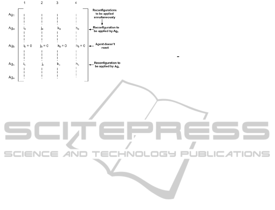
Figure 1: A Coordination Matrix.
agent Ag
b
(b ∈ [1, n]) which is not required to ap-
ply any reconfiguration when others perform scenar-
ios defined in CM. In this case:
CM[b, 1] = CM[b, 2] = CM[b, 3] = CM[b, 4] = 0
cond
a
CM[a,1]
= cond
a
CM[a,2]
= cond
a
CM[a,3],CM[a,4]
= True
We denote in addition by ξ(Sys) the set of coordi-
nation matrices to be considered for the reconfigura-
tion of the distributed system Sys. Each Coordination
MatrixCM is applied at run-time if for each agent Ag
a
(a ∈ [1, n]) the following conditions are satisfied:
cond
a
CM[a,1]
= cond
a
CM[a,2]
= cond
a
CM[a,3],CM[a,4]
= True
On the other hand, we define Concurrent Coor-
dination Matrices, CM
1
and CM
2
two matrices of
ξ(Sys) that allow different reconfigurations of same
agents as follows: ∃b ∈ [1, n] such that:
• CM
j
[b, i] 6= 0 ∀ j ∈ {1, 2} and i ∈ [1, 4],
• CM
1
[b, i] 6= CM
2
[b, i] ∀i ∈ [1, 4].
In this case, the agent Ag
b
is disturbed because
it has to apply different reconfiguration scenarios at
the same time. To guarantee a deterministic behavior
when Concurrent Coordination Matrices are required
to be simultaneously applied, we define priority lev-
els for them such that only the matrix with the highest
priority level should be applied. We denote in the fol-
lowing by:
• Concur(CM) the set of concurrent matrices of
CM ∈ ξ(Sys),
• level(CM) the priority level of the matrix CM in
the set Concur(CM) ∪ {CM}.
Running Example. For the sake of simplicity, we
take as example only two matrices CM
2
and CM
6
(in
(Gharbi et al., 2010a) the reader will find more details
on all possible coordination matrices).
• the matrix CM
2
is applied when the FESTO Agent
applies the High Production mode (i.e. the states
ASM
2
, CSM
21
and DSM
21
are activated and
Reconfiguration
2,1,2,1
is applied) and the EnAS
Agent is required to increase the productivity by
applying the Second Production mode to put two
pieces into each tin (i.e. the states ASM
1
, CSM
11
are activated and Recon figuration
1,1,0,0
is ap-
plied),
• the matrix CM
6
is applied when the Drilling ma-
chine Drill
machine1 is broken in FESTO (i.e.
the states ASM
2
, CSM
23
and DSM
23
are activated
and Reconfiguration
2,3,2,3
is applied). In this
case EnAS system is required to decrease the pro-
ductivity by applying the First Production mode
(i.e. the states ASM
2
, CSM
21
are activated and
Reconfiguration
2,1,0,0
is applied),
3.2 Coordination between Distributed
Agents
We propose a multi-agent architecture for control sys-
tems following the Standard IEC61499 to handle au-
tomatic distributed reconfigurations of devices. To
guaranteea coherent behaviorof the whole distributed
system, we define a Coordination Agent (denoted by
CA(ξ(Sys))) which handles the Coordination Matri-
ces of ξ(Sys) to control the rest of Control Agents (i.e.
Ag
a
, a ∈ [1, n]) as follows:
• When a particular Control Agent Ag
a
(a ∈
[1, n]) should apply a reconfiguration scenario
Reconfiguration
a
i
a
, j
a
,k
a
,h
a
(i.e. under well-defined
conditions), it sends the following request to
CA(ξ(Sys)) to obtain its authorization:
request(Ag
a
,CA(ξ(Sys)), Reconfiguration
a
i
a
, j
a
,k
a
,h
a
).
• When CA(ξ(Sys)) receives this request that cor-
responds to a particular coordination matrix CM
∈ ξ(Sys) and if CM has the highest priority be-
tween all matrices of Concur(CM) ∪ {CM}, then
CA(ξ(Sys)) informs the Control Agents that have
simultaneously to react with Ag
a
as defined in
CM. The following information is sent from
CA(ξ(Sys)):
For each Ag
b
, b ∈ [1, n] \ {a} and CM[b, i] 6= 0, ∀
i ∈ [1, 4]:
reconfiguration(CA(ξ(Sys)), Ag
b
,
Reconfiguration
b
CM[b,1],CM[b,2],CM[b,3],CM[b,4]
)
• According to well-defined conditions in the de-
vice of each Ag
b
, the CA(ξ(Sys)) request can be
accepted or refused by sending one of the follow-
ing answers:
– If cond
b
i
b
= cond
b
j
b
= cond
b
k
b
,h
b
= True
Then the following reply is sent from Ag
b
to
CA(ξ(Sys)):
ModelCheckingofDistributedComponent-basedControlSystems
515

possible reconfig(Ag
b
,CA(ξ(Sys)),
Reconfiguration
b
CM[b,1],CM[b,2],CM[b,3],CM[b,4]
).
– Else the following reply is sent from Ag
b
to
CA(ξ(Sys)):
not
possible reconfig(Ag
b
,CA(ξ(Sys)),
Reconfiguration
b
CM[b,1],CM[b,2],CM[b,3],CM[b,4]
).
• If CA(ξ(Sys)) receives positive answers from all
Control Agents, Then it authorizes reconfigura-
tions in the concerned devices:
For each Ag
b
, b ∈ [1, n] and CM[b, i] 6= 0, ∀ i ∈
[1, 4],
apply(Reconfiguration
b
CM[b,1],CM[b,2],CM[b,3],CM[b,4]
)
in device
b
.
Else If CA(ξ(Sys)) receives a negative answer
from a particular Control Agent, Then
CA(ξ(Sys)) permits Ag
a
, on the one hand, to apply
the requested reconfiguration scenario by sending
the following reply:
apply(Reconfiguration
a
CM[a,1],CM[a,2],CM[a,3],CM[a,4]
).
CA(ξ(Sys)) informs the other Control Agent Ag
b
,
on the other hand, to cancel the new reconfigura-
tion.
For each Ag
b
, b ∈ [1, n] and CM[b, i] 6= 0, ∀ i ∈
[1, 4],
cancel(Reconfiguration
b
CM[b,1],CM[b,2],CM[b,3],CM[b,4]
)
in device
b
.
Running Example. In our FESTO and EnAS Bench-
mark Production Systems, we show in Figure 2 the co-
ordination between these Control Agents when Jack1
is broken in EnAS. In this case, the Coordination
Agent uses the Matrix CM to decrease the productiv-
ity in FESTO.
4 MODEL CHECKING OF
COMMUNICATION
PROTOCOL
To verify some properties, the use of Model-Checker
SESA is well justified. In fact, it offers a wide range
of functionalities. At first, the NCES formalism is
an extension of the Petri Net. Secondly, it permits to
represent concurrent process. Thirdly, there are sev-
eral tools associated to NCES enabling the generation
of reachability graph, the verification of some proper-
ties, Finally, the verification of some properties using
the Computation Tree Logic (CTL) (Roch, 2000) with
the model checker SESA.
EnAS agent
FESTO agent
Coordination agent
Request(EnAS, CA, Reconfiguration
1,2,0,0
)
Reconfiguration(CA, FESTO, Reconfiguration
1,1,1,1
)
Jack1 is broken
Drill station D1 is OK
Possible_reconf(FESTO, CA, Reconfiguration
1,1,1,1
)
Apply(Reconfiguration
1,2,0,0
) Apply(Reconfiguration
1,1,1,1
)
1 1 1 1
1 2 0 0
CM
Figure 2: Coordination between the FESTO and EnAS
agents when Jack1 is broken.
In this section, we aim to specify and verify the
Communication Protocol through the NCES editor
and the model checker SESA. This is the real contri-
bution of this paper which is based on related previous
published papers.
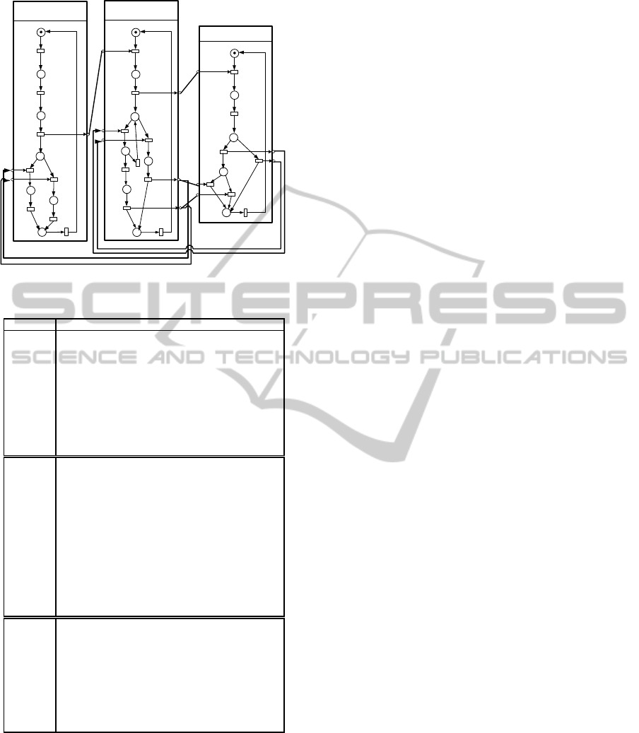
In the Communication Protocol, we distinguish three
kinds of participating agents:
• The Control Agent
i
: it is the Control Agent which
starts the communication. In fact, wheneveran er-
ror occurs in a specific plant, the associate Control
Agent tries to correct it and if it decides the neces-
sity of reconfiguration the whole system (i.e. the
other Control Agents must be aware of this modi-
fication) it informs the Coordination agent.
• The Coordination agent (CA): it is the main agent
which has as task the coordination between the
different Control Agents. Thus, when the coordi-
nation agent receives the request of reconfigura-
tion, it searches the list of Control Agents which
must be informed. It sends a request to these Con-
trol Agents and waits the response from them.
• The Control Agent
j
: it is the j
th
Control Agent
that receives a request from Coordination agent
for reconfiguration. Firstly, it checks the possi-
bility to apply a reconfiguration. If it is possible,
it sends a positive answer. If it is not possible,
it sends a negative answer (see Figure 3). For
further information, we refer to Table 1.
CTL Properties
The following CTL properties are proven to be true
by the model checker SESA:
Property 1. Always, when an error occurs in the
plant, the Control Agent
i
informs the Coordination
Agent.
AG (P2 => EF P9)
This property is proven to be true by SESA tool.
Property 2. During the negotiation, the Coordination
Agent waits the response from the other agents
ICSOFT2013-8thInternationalJointConferenceonSoftwareTechnologies
516
P1
t8
t1
t2
t3
P4
P6
t6
t4
P2
P3
t5
P5
t7
P7
P8
t17
t9
t10
P10
P13
t15
t11
P9
t12
P11
t16
P14
t13
P12
P15
t24
t18
t19
P17
P19
t23
t20
P16
t22
t21
P18
Control Agent
i
Coordination Agent
Control Agent
j
ei1
ei2
ei3
ei4
ei5
ei6
eo1
eo3
eo4
eo5
eo6
ei7
ei8
eo2
N-1
t14
Figure 3: Communication Protocol.
Table 1: The meaning of transitions related to Figure 3.
Transition Meaning
t
1
An error occurs
t
2
The Control Agent
i
decides a new reconfiguration
t
3
The Control Agent
i
informs the coordination agent
t
4
The Control Agent
i
receives a negative answer
from the coordination agent
t
5
The Control Agent
i
applies the new reconfiguration
t
6
The Control Agent
i
receives a positive answer
from the coordination agent
t
7
The Control Agent
i
applies the new reconfiguration
with the other
t
8
The end of communication process
t
9
The Coordination Agent receives a request
t
10
The Coordination Agent sends to other agents
t
11
The Coordination Agent receives a positive answer from
a specific agent
t
12
The Coordination Agent receives a positive answer from all
concerned agents
t
13
The Coordination Agent asks the other agents to apply a new
reconfiguration
t
14
The Coordination Agent waits (either positive or negative)
response from the other agents
t
15
The Coordination Agent receives a negative answer
t
16
The Coordination Agent asks the initiator to apply
the reconfiguration
t
17
The end of communication process
t
18
An Control Agent
j
receives the request for
reconfiguration
t
19
The Control Agent
j
verifies some constraints
t
20
The Control Agent
j
accepts the new reconfiguration
t
21
The Control Agent
j
receives disapproval from
the coordination agent
t
22
The Control Agent
j
receives approval from
the coordination agent
t
23
The Control Agent
j
refuses the new reconfiguration
t
24
The end of communication process
(Control Agent
j
) or receives disapproval from a
specific agent.
EF P10 AND EF (P11 OR P14)
This formula is proven to be true by SESA tool.
Property 3. The Control Agent
i
could not receive
two different notifications from the Coordination
Agent at the same time (i.e. notification that the other
agents accept and refuse the new reconfiguration ).
NOT EF (P5 AND P7)
This property is proven to be true by SESA tool.
eCTL properties
The following eCTL properties are proven to be true:
Property 4. Whenever the Control Agent
j
accepts
the new reconfiguration, it waits the final decision
from the Coordination agent which can be a confir-
mation to apply a new reconfiguration or to cancel
the new reconfiguration.
AGA t20 XAGA (t21 OR t22) X p19
Property 5. We want to check the correctness of the
communication protocol:
1. Firstly, an error occurs, so the associated agent
(Control Agent
i
) decides a new reconfiguration;
2. The Control Agent
i
informs the Coordination
Agent to start the negotiation with the other
agents;
3. The Coordination Agent sends a request to other
agents (each agent is considered as Control
Agent
j
);
4. The Control Agent
j
receives the request, verifies
its constraints (to check the feasibility) and then
decides to accept or refuse the new reconfigura-
tion.
AG A t1 X AG A t3 X AG A t9 X AG A t10 X AG A
t18 X AG A t19 X p17
This property is checked to be true.
5 COMMUNICATION
PROTOCOL
IMPLEMENTATION
We developed a complete tool ”ProtocolReconf” at
INSAT Institute by using Qt Creator 2.0.0 (for more
information we refer to http://qt.nokia.com/products).
We firstly present its different graphic interfaces be-
fore we show a simulation verifying the communi-
cation protocol. The tool ”ProtocolReconf” offers
the possibility to create the Control and Coordina-
tion Agents by introducing their parameters. For the
Control Agent (Figure 4), it is necessary to define the
Data, Devices, Reconfigurationsand Rules. Each data
must be defined by indicating its name and value, and
each device is characterized also by its identifier and
state (functional or broken). It is required to define the
different scenarios that the Control Agent can support
so that when a modification occurs in the system, it
should look for the convenient reconfiguration. For
ModelCheckingofDistributedComponent-basedControlSystems
517
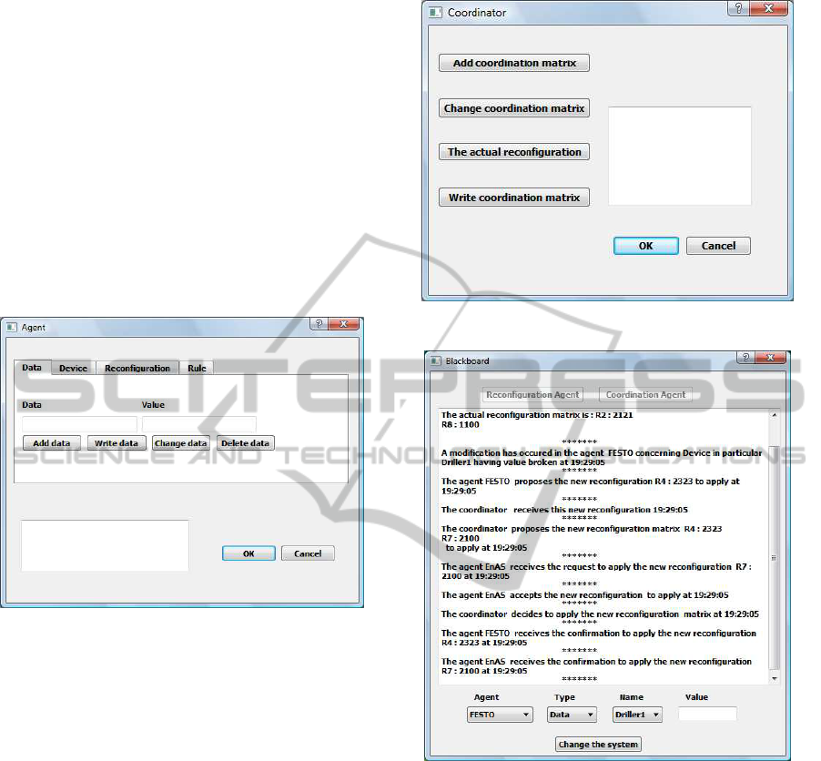
the Coordination Agent (Figure 5), it is necessary to
define the set of Coordination Matrices and especially
the current matrix to apply to the whole system. The
communication between the different Control Agents
follows the specific protocol defined in the previous
section. To ensure a new reconfiguration, a Control
Agent sends a request to the Coordination Agent in-
dicating the new reconfiguration to apply. Conse-
quently, this Coordinator searches the right Coordina-
tion Matrix and sends a request to the rest of Control
Agents. After receiving all the feedbacks, the Coor-
dination Agent decides to apply this new coordina-
tion matrix (if all Control Agents accept this modifi-
cation) or to cancel the corresponding reconfiguration
scenario.
Figure 4: Control Agent.
Running Example. In FESTO and EnAS Benchmark
Production Systems (Figure 6), we assume that the
matrix CM
2
is applied i.e. the FESTO’s agent applies
the High Production mode and the EnAS’s agent ap-
plies the Second Production strategy. To verify the in-
teraction between these agents when a particular hard-
ware problem occurs, we change the state of the de-
vice Driller1 which becomes broken. Consequently,
the FESTO’s agent should decrease the production by
sending a request to the Coordination Agent in order
to look for the most convenient matrix which is CM
6
.
The Coordination Agent sends a request to decrease
the production in EnAS. The EnAS’s agent studies
the feasibility of this new reconfiguration in order to
accept the decrease of production. In this case, the
Coordination Agent sends a final confirmation to of-
ficially apply this new coordination matrix.
6 CONCLUSIONS
This paper deals with the Model Checking of dis-
tributed safety control systems by following a multi-
Figure 5: Coordination Agent.
Figure 6: Example of Communication Protocol.
agent architecture. We define an agent-based archi-
tecture where each agent (associated to a defined de-
vice) controls the environment evolution and applies
automatic reconfigurations when hardware errors oc-
cur at run-time to guarantee a functional safety of
the whole system. Each control agent is affected in
this architecture to a device of the execution envi-
ronment to ensure safety. Besides, the Coordination
Agent is responsible for the interaction between Con-
trol Agents in order to ensure a mutual agreement
with the others on a reconfiguration to apply. We
present therefore a communication protocol between
these agents using Coordination Matrix specifying for
each Control Agent the reconfiguration to apply ac-
cording to predefined conditions. The model check-
ing is very interesting method to prove the correctness
ICSOFT2013-8thInternationalJointConferenceonSoftwareTechnologies
518

of the communication protocol represented with the
NCES. Finally, the ”ProtocolReconf” tool is used to
simulate the communication protocol.
In the future work, we plan to study the failure re-
covery functionality realized by the Control Agent in
order to provide the corrective measures to avoid the
failures due to hardware or software default. We aim
to study also the functionality covering the acquisi-
tion of data from and the forwarding of commands
(through the sensors and the actuators) to the physical
plant ensured by the Control Agent.
REFERENCES
Diedrich, C. and all (2004). Function block applications in
control systems based on iec 61804. ISA Transactions,
43:123131.
Gharbi, A., Khalgui, M., and Ahmed, S. B. (2010a). Inter-
agents communication protocol for distributed recon-
figurable control software components. The Interna-
tional Conference on Ambient Systems Networks and
Technologies (ANT), 8-10 Novembre.
Gharbi, A., Khalgui, M., and Ahmed, S. B. (2010b). Model
checking optimization of safe control embedded com-
ponents with refinement. 5th International conference
on Design and Technology of Integrated Systems in
Nanoscale Era.
Gharbi, A., Khalgui, M., and Ahmed, S. B. (2011a). Agent-
based fault management of embedded control sys-
tems. 6th International Conference on Software and
Data Technologies (ICSOFT), 18-21 Juillet.
Gharbi, A., Khalgui, M., and Ahmed, S. B. (2011b). Func-
tional safety of discrete event systems. First Workshop
of Discrete Event Systems.
Gharbi, A., Khalgui, M., and H-M.Hanisch (2009). Func-
tional safety of component-based embedded control
systems. 2nd IFAC Workshop on Dependable Control
of Discrete Systems.
Goessler, G., Graf, S., Majster-Cederbaum, M., Martens,
M., and Sifakis, J. (2007). An approach to modeling
and verification of component based systems.
Hanisch, H.-M. and Luder, A. (1999). Modular mod-
elling of closed-loop systems. in Colloquium on
Petri Net Technologies for Modelling Communication
Based Systems, pages 103–126.
Jennings, N. R., Sycara, K., and Wooldridge, M. (1998).
A roadmap of agent research and development. Au-
tonomous Agents and Multi-agent Systems, 1:7–38.
Khalgui, M., H-M.Hanisch, and Gharbi, A. (2009).
Model-checking for the functional safety of con-
trol component-based heterogeneous embedded sys-
tems. 14th IEEE International conference on Emerg-
ing Technology and Factory Automation.
Rausch, M. and Hanisch, H.-M. (1995). Net condition/event
systems with multiple condition outputs. in Sympo-
sium on Emerging Technologies and factory Automa-
tion, 1:592–600.
Roch, S. (2000). Extended computation tree logic: Im-
plementation and application. In Proceedings of the
AWPN2000 Workshop.
SZYPERSKI, C., GRUNTZ, D., and MURER, S. (2002).
Component Software Beyond Object-Oriented Pro-
gramming. The Addison-Wesley Component Soft-
ware Series.
van Ommering, R., van der Linden, F., Kramer, J., and
Magee, J. (2000). The koala component model
for consumer electronics software. IEEE Computer,
33:78–85.
Wittig, T. (1992). Archon: An architecture for multi-agent
system. Ellis Horwood, Chichester.
ModelCheckingofDistributedComponent-basedControlSystems
519
