
MORPHO-Map
A New Way to Model Animation of Topological Transformations
Annie Luciani
1, 3
, Ali Allaoui
2, 1
, Nicolas Castagné
1, 3
,
Emmanuelle Darles
2
, Xavier Skapin
2
and Philippe Meseure
2
1
Laboratoire ICA, Institut Polytechnique de Grenoble, Université Grenoble Alpes, Grenoble, France
2
Laboratoire XLIM, Université de Limoges-Poitiers, Poitiers, France
3
ACROE, Ministère de la Culture et de la Communication, Grenoble, France
Keywords: Computer Animation, Topological Transformations, Particle-based Animation, Combinatorial Maps,
Fractures.
Abstract: Animation of topological transformations, such as fractures, cracks, tears, crumbles or fragmentations, is a
new challenge in Computer Graphics and Animation. We propose a new way to model and animate
topological changes, allowing the programmer to design any type of topological changes and animation
mapping. This model is based on organizing the complex modeling activity into three clearly defined
simpler sub-activities: 1) point-based animation, which enables a wide variety of possible temporal
phenomena; 2) topological-based modeling, which makes it possible to manage a wide variety of shape-
independent topologies and topological transformations; 3) free, non predetermined, association between
both, and 4) final output of an animated geometrical model exhibiting any complex behavior. We
experimented the proposed method by modeling tearing effects on deformable garments, on rifts and crack
effects on 3D objects, and finally by modeling imaginary and paradoxical topological transformations
associated with realistic Physics-based animation. Besides improving the consistency and the robustness of
the modeling process of such complex phenomena, our aim is also to offer a user-centered programming
environment to the Computer Graphics and Animation programmers and designers, to enlarge their
modeling and experimentation abilities, and to stimulate their creativity.
1 INTRODUCTION
Computer Animation is currently able to produce
complex animations of rigid solids, deformable
objects or fluids by mixing physical behaviors with
complex shapes. A new challenge is now to handle
extreme deformations leading to dynamical
topological changes, as they occur in very frequent
complex visual phenomena such as breaking,
cutting, tearing or merging. In that context, most of
existing methods are based on creating geometrical
shapes with physical behaviors, for instance by
using finite elements methods and by applying
geometrical and physical transformations via
detected events such as thresholds in stresses.
However, these methods usually imply re-meshing
operations that are even more complex, since they
induce both physical and geometrical re-meshing.
On both physical and geometrical sides, this may
introduce computational drawbacks, such as
temporal instabilities for the first and topological
inconsistencies for the second. That leads to include
all of the necessary optimizations and specific
arrangements to overcome these problems within the
implemented program. As a consequence, the
modeling process is obviously specific to the
phenomenon to be obtained and it cannot be used in
a general way.
We present here an approach based on a clearly-
cut dissociation of the animation stage from the
topological and geometrical stages, in order (1) to be
able to map an existing animation on any shape and
(2) to take topological transformations into account
all along the animation.
The proposed approach is particularly well
adapted for particle-based meshless animation with
no a priori shape, and moreover, for animation
produced by physically based particle modeling.
Thus, the model is composed of two communicating
parts, the first part producing point-based motions
288
Luciani A., Allaoui A., Castagné N., Darles E., Skapin X. and Meseure P..
MORPHO-Map - A New Way to Model Animation of Topological Transformations.
DOI: 10.5220/0004674002880300
In Proceedings of the 9th International Conference on Computer Graphics Theory and Applications (GRAPP-2014), pages 288-300
ISBN: 978-989-758-002-4
Copyright
c
2014 SCITEPRESS (Science and Technology Publications, Lda.)

and the second part being responsible for the
modeling of shapes, including a topological level,
controlled by the previously produced motion.
In addition, particle-based meshless animation,
such as those proposed for instance in (Luciani et al.,
1991), (Pauly et al., 2005), (Wojtan et al., 2009), is
well suited to model transformations or
metamorphosis. Moreover, it is well adapted for
modeling hard topological transformations due to
physical extreme deformations or clearly-cut
changes that occur in fragmentation, breaking,
cracking, tearing, etc.
This paper proposes a new method for generating
complex animations based on three modeling stages:
point-based animation, topological models and
geometrical models, the first level controlling the
topological and geometrical transformations of the
two other levels. These three modeling stages and
their association are supported by a programming
framework, called MORPHO-Map, allowing
programmers to program any kind of topological
models and their association with a point-based
animation, hence to create any variety of animated
shapes transformations.
The paper is organized as follows: Section 2
reviews related works aiming at pinpointing
MORPHO-Map inside the context of Computer
Animation and Topological transformations
modeling; Section 3 presents the theoretical aspects
of MORPHO-Map modeling process; Section 4
details the components of MORPHO-Map modeling
framework; finally, Section 5 illustrates the
modeling MORPHO-Map process by means of
several models: tearing effects on deformable
garments with propagations and ravels, internal
fissures and brittle fractures of 3D rigid objects, and
finally imaginary topological transformations of a
physically-based deformable box.
2 RELATED WORKS
In Computer Animation, it could be useful to
distinguish between three types of approaches: (1)
interactive software implementations, such as Maya
or Blender, and a lot of others; (2) general methods
such as implicit surfaces; and (3) specific algorithms
dedicated to a type of phenomena, for instance
simulations of fluids, fractures, crowds, etc. In the
following, we will examine briefly those main
streams in order to situate our proposition.
Interactive software mainly allow their user to
interactively model shapes, including volumetric
geometry, meshed shapes, skeletons and skinning
processes; those shapes are animated by applying
time-based functions on them, for instance key-
framing, direct and inverse kinematics, motion
blending and retargeting, etc. The modeling activity
is performed through a high-level Human-Computer
Interface. However, these software have been
preferably designed to target solid rigid or
deformable objects, though they sometimes include
specific plug-ins such as particle modeling for
fluids, explosions, vortices, and so on. Consequently
and unfortunately, modeling dynamic topology
changes is not directly accessible to the user, since
topological changes would require to re-design the
geometrical model, for example to redesign the
meshed representation of the objects.
Among methods dedicated to the animation of
soft objects, implicit surfaces avoid any explicit
representation of 2D parametric or meshed surfaces,
3D volumes, etc. An implicit potential function is
associated with each element of a skeleton, for
example a point, to thicken it, either statically
(Desbrun and Cani, 1995) or dynamically (Habibi
and Luciani, 2002). These methods automatically
produce topological changes according to the spatial
proximity of the underlying skeletons. However,
even when they are improved by adding blending
graphs to avoid unwanted blending, the topological
changes are restricted to the specific case of
blending. They do not allow modeling other types of
topological changes such as cracks, fractures,
tearing, breakings, transformations or
metamorphosis, in any place and at any time.
When one wants to handle topology changes
such as fractures as they occur in solids or surfaces,
or during fragmentations, and merging as they occur
in drops of fluids, current methods fall back to
dedicated algorithms.
In regards to solid fragmentations and fractures
modeling, most works root on physically-based
finite elements algorithms including critical physical
re-meshing during simulation (O’Brien et al., 2002),
(Bao et al., 2007), (Molino et al., 2004). Some works
avoid such physical remeshing by using other
methods to determine fracture localization (Glondu
et al., 2013). In all these cases, the geometrical
remeshing of the fragment surfaces, for instance by
means of geometrical replications and refinements
all along the fracture lines (Molino et al., 2004)
(Glondu et al., 2013), remain a specific and quite
complex operation since it must include the
verification of the geometrical consistency of each
created mesh.
In regards to fluid topological transformations,
Computer Graphics works propose specific
MORPHO-Map-ANewWaytoModelAnimationofTopologicalTransformations
289

processing for droplets formation and merging
within an algorithmic framework, based on mixing
propagations of wavefronts and Smooth Particles
Hydrodynamics (Losasso et al., 2008) or by
adequately mixing Lagrangian and Eulerian methods
(Irvin et al., 2006).
In all these cases, the algorithms correspond to
one-shot models within which all the aspects
(physics, animation, shape changing) are tightly
integrated and closely tied to each other. They
cannot be used for other types of shapes and
topological transformations, except those taken into
account in the algorithm itself.
Other series of methods are developed in the
domain of topological modeling, such as those based
on the constructive topological modeling approaches
called Combinatorial Maps. Starting from the
modeling of topological relationships by means of
G-Maps (Lienhardt, 1994), some works aimed at
programming evolutions of surfaces or surfaces
metamorphosis (Chen and Lienhardt, 1992) as
needed in geological studies. Some others aimed at
programming evolutions of natural objects (leafs,
plants, etc.) as performed by means of L-systems
(Prusinkiewicz, Lindenmayer, 1990). These methods
enable modeling of a wide variety of topologies and
topological changes. However, control of the
evolutions is directly made within the program
defining the topological model. Thus, the user does
not have access to evolutions coming from external
data, for example from data provided by physical,
biological or genetic externally modeled events.
It appears that none of these tools and methods is
able to propose a generic and modular concept, nor
to support a user-friendly framework allowing to
model freely complex animated transformations.
Indeed, to our knowledge, few works aim at
controlling topological transformations in a generic
way, particularly by Physics. An example of such an
approach can be found in works performed at the
Cornel Fracture Group by physicists (Carter et al.,
1995, 2008) in matter stresses. In these works, two
separated models are used: one for the physical
properties and one for the spatial topological
representations according to operations that are
similar of those mathematically defined in
topological G-Maps (vertex, edge, face and volume
sewing and unsewing).
We propose a modeling framework, called
MORPHO-Map, aiming to overcome some of the
limitations described previously. MORPHO-Map is
based on four principles:
(1) The separation between the animation modeling
stage and its topological and geometrical effects
as those performed in (Meseure et al., 2010)
(Darles et al., 2011) (Fléchon et al. 2013).
(2) The choice of point-based animation, such as
mass-interaction modeling, as proposed in
(Luciani et al., 1991) in order to be as generic as
possible on the side of animation modeling.
(3) The introduction of a topological modeling stage,
and hereto the choice of constructivist
environments such as those based on G-Maps
(MOKA) (CGoGN) in order to offer topological
modeling tools to the programmers that are
generic and robust according to their formal
well-founded theoretical rules. The geometrical
meshed representations will then be obtained by
means of geometrical mappings of topological
models, such as used in (Bézin et al., 2011).
(4) From an existing point-based animation, and an
initial topological model, we define
programming processes allowing the user to
design associations between both, in order to
animate the second with the first, including deep
discontinuous topological evolutions, therefore
enabling the management of any type of shape
transformation and metamorphosis.
A first interest of the very distinction between
the animation stage and the topo-geometrical stage,
as proposed in this article, appears clearly when
using physical modeling to drive the topological
changes processes. Indeed, the current works in
which physical modeling and topological changes
are associated, as those quoted in this state of the art,
are grounded on the strong assumption of a spatial
continuum and of a material contiguity. This
assumption leads naturally to adopt techniques such
as Finite Elements Methods and their two main
derivatives used in Computer Animation: (1)
Meshless (or Meshfree) Methods, as developed from
the Diffuse Element Method (DEM) initiated by
(Nayrolles et al. 1992) and (2) masses-springs
methods mapped onto geometrical meshes. Although
such methods constitute a solid background for
modeling deformations of complex, they introduce
two critical drawbacks when associated:
(1) Modifying the geometry leads to change the
topology of the physical part, and thus may
affect the numerical stability of the physical
model, which is a touchstone aspect in physical
modeling;
(2) The computation of the physical part becomes
more and more cumbersome when the number of
physical constraints (for example the number of
springs in meshed masses-springs methods) or
the number of computation points in meshless
methods increase all along the improvement of
GRAPP2014-InternationalConferenceonComputerGraphicsTheoryandApplications
290
the geometrical resolution by the refinement
processes, necessary for the final wanted images.
This in contradiction with the fact that physics
simulation must run faster than geometrical and
topological algorithms to ensure numerical
stability and quality of physics behaviors.
Conversely, the formal architecture proposed in
this article, based on a clearly-cut dissociation
between the physical part and the topo-geometrical
part, allows adapting the resolution and the
computation rates of each part to its own true needs.
A second interest of this formal organization of
the modeling process is to be well-suited to support
a modularized modeling pipeline, allowing
Computer Animation users and designers to
experiment the association between point-based
motions and topological and geometrical models, as
freely as possible, to generate a wide variety of
animated evolutionary shapes, and to empower the
user with advanced mastering of modeling,
experimenting and creating using the modeling
processes.
We can notice here that two ways may be
distinguished when aiming at allowing the user to
program topological changes. The first way consists
in specifying topological changes at the
phenomenological level – as we “see” them directly.
In these types of phenomenology-based models,
cracks patterns are phenomenologically predesigned,
for example from images. Then, the patterns can
afterwards be mapped on any shape according to a
logico-geometric process (Desbenoit et al., 2005), or
used to drive optimization processes (Glondu et al.,
2012). The second way, proposed in this article, is
rooted on the possibility to modularize the modeling
process in order to provide elementary combinable
modules, from which the user can program his/her
own topological changes associated to a given
animation.
3 MORPHO-Map PRINCIPLES
MORPHO-Map’s process results in animating
evolutionary meshed shapes exhibiting topological
modifications. The inputs of the process are a set of
moving points called Animation Functions Set and
an initial topological Generalized Map (G-Map).
This section details the MORPHO-Map principles:
(1) to animate a topological model; and (2) to handle
topological transformations of the topological model
and of subsequent modifications of the animation
process.
3.1 MORPHO-Map Inputs
3.1.1 Animation Functions Set
The point-based motion input of MORPHO-Map is
called Animation Functions Set, emphasizing both
the facts that the moving points can possibly be
undifferentiated and unstructured, and that the
motion is globally considered as a whole.
As input of the system, we use a coding format
called Gesture and Motion Signal (GMS) (Luciani et
al., 2006). This format is well adapted since it is
low-level enough to input into MORPHO-Map any
point-based motion: the GMS format encodes the
motion of any number of geometrical points in any
dimension (1D, 2D, or 3D). In addition, this format
allows recording motions generated from the
computation of physics-based mass-interaction
models (Evrard et al., 2006), such as those used in
the experimentations of MORPHO-Map (Section 5).
3.1.2 Topological Generalized Maps Models
In order to benefit from a manageable representation
of the topology and to ensure topological
consistency all along the process, we propose to use
a robust topological constructivist formalism, called
the Generalized Combinatorial Maps or G-Maps
(Lienhardt, 1994).
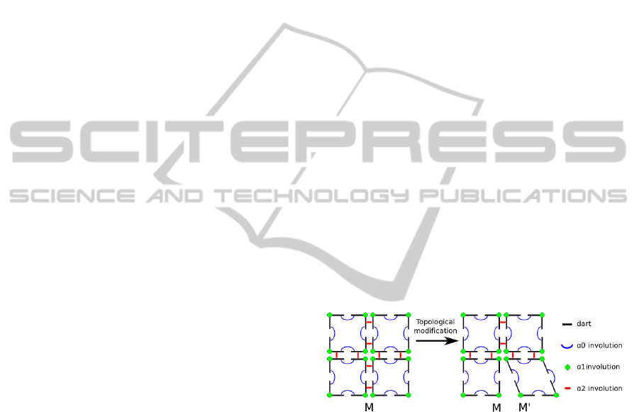
Figure 1: A 2-dimensional topological generalized map
(left) and its transformation (right). Unsewing pairs of
involutions
2
causes a topological split of vertex M,
leading to the creation of a new independent vertex M’.
Within this formalism, a combinatorial map is used
to subdivide a topological space into cells
representing quasi-manifolds. Those cells are
topological vertices, edges, faces, or volumes,
according to their topological dimension (figure 1).
A topological cell is modeled by grouping atomic
elements, called darts, by means of functions called
involutions. For instance, inside a 2D G-Map, a
topological edge is modeled by sewing two darts
with an involution
0
. A topological vertex is
modeled by sewing two darts with an involution
1
,
and the connection of two faces is modeled by
sewing two edges by two involutions
2
– one for
each pair of darts, and so on. The modeling process
MORPHO-Map-ANewWaytoModelAnimationofTopologicalTransformations
291

can continue by creating topological volumes or any
model of any dimension (as long as it is a quasi
manifold). Conversely, cells can be unsewed to
separate entities. In addition, this topological
modeling process allows retrieving adjacency
relationships between cells in a very fast and robust
way.
These principles enable building and
transforming topological models in a constructive
and formally consistent way. Indeed, the G-Map
modeling rules regarding darts and involutions
guarantee that any topological modification respects
topological integrity constraints, and always results
in a consistent topological G-Map structure.
Finally, a geometrical model is obtained from a
topological G-Map by mapping the cells of the G-
Map onto a geometrical space. This process, called
geometrical embedding, can be achieved in a
coherent and flexible manner.
In the work presented in this article, we used the
G-Maps code proposed in the CGoGN C++ library
(CGoGN). In addition to the core features of the G-
Maps formalism, CGoGN offers a flexible attribute
manager allowing to embed any information into
darts or cells. This feature can be used to encode
various properties throughout MORPHO-Map, e.g.
to embed the geometrical mapping and visual
rendering mapping of the topological model. For
instance, it allows associating topological vertices
with geometrical positions, topological faces with
colors, etc.
When starting the MORPHO-Map process, an
initial topological G-Map has to be set up. This
initial G-Map can be designed by the user explicitly
with manipulation of the topological darts. It can
also be created automatically from any geometrical
mesh model, or from the positions of the moving
points at a chosen frame in the animation functions
(Darles and al., 2011). In every case, the user may
modify the initial G-Map until obtaining the needed
topological model, by adding or removing darts or
sewing and unsewing cells.
3.2 Principles for Animation
and Topological Transformations
From both inputs (an Animation Functions Set and
an initial G-Map), MORPHO-Map consists, at each
frame, in (1) computing and animating the
geometrical mapping of the current G-Map; and (2)
transforming the topology of the G-Map to provide a
new G-Map.
3.2.1 Animation Process
The mapping of the G-Map onto the geometrical
space is based on a direct low-level association
between elementary topological cells and
geometrical elements. The geometrical model is
generated at each frame from the current topological
G-Map. Animation consists in computing, at each
frame, from the animation functions, the
displacement (e.g. the new position) of the
geometrical model corresponding to the current state
of the topological G-Map. Hence, there is no need of
any geometrical mesh transformation since
transformations are fully and consistently achieved,
on each frame, at the topological level.
In order to be as general as possible with regards
to the association between the Animation Functions
Set and the topological cells, and further their
corresponding geometrical elements, the animation
process is based upon on the control concept as
follows.
As a starting remark, the number of motions of
the Animation Functions Set and the number of
topological cells (and consequently, the number of
geometrical elements) are usually not the same.
Therefore, the animation control process is based on
a clustering principle, by which subsets of motions
of the Animation Functions Set are freely associated
with subsets of cells of the topological G-map:
Clustering structure := Set of{subset of AFS
points, subset of topological cells}.
The clustering principle enables to define in a
flexible manner how an animation function should
influence the mapping of parts of the topological
model, or conversely how the mapping of a given
topological cell is influenced by a subset of the
Animation Functions Set. Notice that, depending on
the needs, clusters can be defined either manually, or
by using automated algorithms, such as the flood-fill
algorithms proposed in (Jund et al., 2012) or in
(Glondu et al., 2013).
To perform animation, a geometrical mapping is
applied. It consists in controlling the motions of the
subset of geometrical elements corresponding to the
cluster’s topological cells, from the corresponding
cluster of the animation functions With such a
mechanism, the association between the given point-
based motions and the final meshed-shapes is very
adaptable. Several mapping algorithms can be used,
such as, but not exclusively, barycentric mapping,
clusterized Radial Basis Functions, etc.
GRAPP2014-InternationalConferenceonComputerGraphicsTheoryandApplications
292

3.2.2 Topological Transformations
Handling topological transformations is the most
complex part of MORPHO-Map’s pipeline. It
requires mastering deep modifications of the
topological model and consistent handling of their
consequences all over the pipeline, at each temporal
frame, all along the animation.
In MORPHO-Map, topological transformations
are organized into 4 sub-processes:
• Sensing: It consists in extracting information
from the Animation Functions Set, to control
subsequent topological modifications. Sensing
might be local, such as computing distances or
relative velocity vector between two moving
points, or spanned over a subset of the Animation
Functions. Notice that, when the animation is
physically based, distances can represent the
elastic stress in linear elastic material, and
velocities the viscosity forces. Sensing might not
only consider the current motion frame, but also
several frames altogether. Examples of data
extracted during sensing include, but are not
limited to, thresholds: onto a bi-points distance,
onto a set of bi-point distances, onto an organized
sequence of bi-points distances, between bi-point
relative velocity vectors, and so on.
• Selection process: This step outputs the list of cells
on which the topological modifications will be
applied. The Selection of topological cells is
constituted by the information gathered in the
previous sensing step. Selected cells can be of any
dimension: edges, vertices, faces, or volumes.
Moreover, the clusters may be employed to
express selection of cells in the G-Map. For
example, if Sensing has detected a distance
threshold for two Animation Functions, Selection
may consist in retrieving all the topological cells
that belong at the same time to the pair of clusters
of these two Animation Functions.
• Topological modifications: This sub-process
applies the chosen topological modification onto
the previously selected cells. It relies on the G-
Map formalism to output a consistent modified G-
Map. Any topological modification may be
applied. As an example, if Selection outputs a list
of topological volumes, these volumes might be
deleted, unsewn, or split into topological sub-
volumes, and so on.
• Updating: The topological transformations may
require modifying the clusters configuration, to
ensure their consistency with the new topology.
For example, newly created cells, if any, should be
added to some clusters. In this final sub-process,
clusters might be totally reconfigured, or only
locally updated, depending on the depth of the
topological transformations. Updating is achieved
by considering the current state of the Animation
Functions Set and of the G-Map, and potentially
the previous state of the clusters.
On each frame, once these four topological
modification steps have been applied, the pipeline
turns back to the Animation process, and to the
computation of the new geometrical model.
4 MORPHO-Map FRAMEWORK
As explained in the state of the art, modeling
complex animations exhibiting deep topological
transformations is a new challenge, not only for
modeling as such, but also with regards to the tools
able to facilitate the modeling activity. Indeed,
beside the design of human – computer modeling
software and one-shot models development,
modeling activity of complex phenomena, such as
those expected here (fragmentation, tearing,
breaking, and so on) would take advantages of fast
prototyping tools to increase the number of possible
experimentations, and to trigger new modeling
projects. Such experimentations could consist either
in being able to program easily a given dynamic
phenomenon, as those that already exist in the
scientific literature, or to create and model new
dynamic ones.
The principles exposed in section 3 allow for
flexible and comprehensive modeling strategies.
Furthermore, we consider important to offer to the
user a software environment able to support the
corresponding modeling activity. In these regards,
MORPHO-Map modular principles make it possible
to build over new approaches to programming, such
as those proposed in box-and-wires systems, like in
PureData/GEM, or block languages such as Starlogo
TNG. The following presents the MORPHO-Map
software framework, a hybrid user-centric system
between flow programming and sequence diagrams.
4.1 The Component Abstraction for a
Box-and-Wire Programming Style
MORPHO-Map’s framework relies on box-and-wire
principles, by means of a component abstraction
(figure 2). A component encapsulates: (1) an
execution method: the process; (2) parameters of the
process (3) inputs, that are typed and named; (4)
outputs, that are typed and named.
MORPHO-Map-ANewWaytoModelAnimationofTopologicalTransformations
293
In addition to these notions, the framework relies
on a notion of state variables. State variables
represent all the structured datasets that define the
current state of the system and are needed
transversally throughout the process. The Animation
Functions, the G-Map itself, the clusters and the
resulting geometrical model are hence state
variables in MORPHO-Map’s framework. Any
component may access them any time, as input or
output of its algorithm. The graphical representation
of a component shows the use of state variables by a
component (Figure 2) without the need of heavy
wiring.
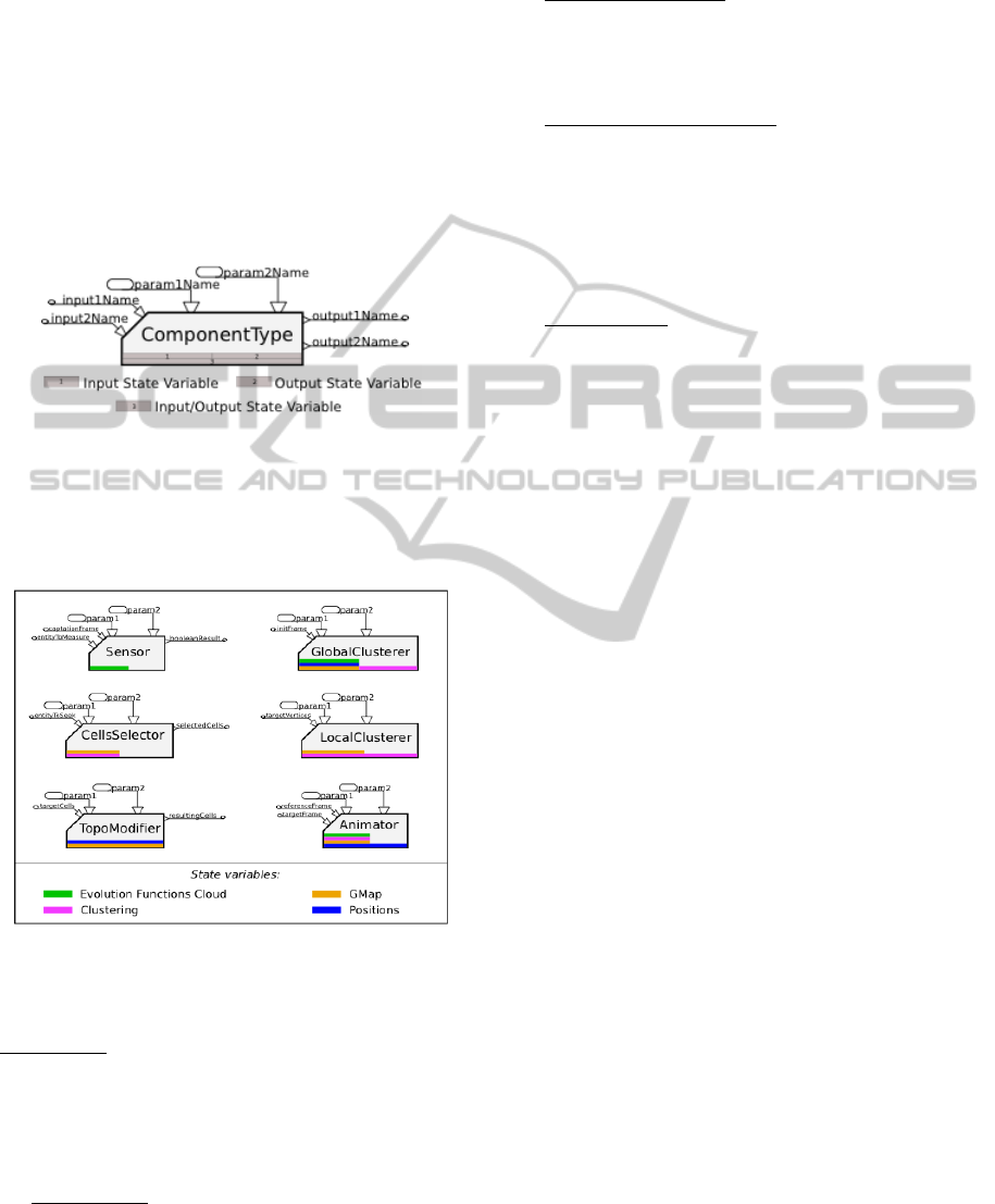
Figure 2: Representation of a MORPHO-Map component.
The four MORPHO-Map sub-processes described
above (sensing, selection, topological modifications
and clusters updating) are encapsulated by means of
5 component families (Figure 3).
Figure 3: MORPHOMAP component families. The
“Clusterer” family is decomposed into two sub-families:
the global and the local clusterer.
1. Sensors: A Sensor component specifies the
extraction to achieve from the Animation Functions
Set. Sensors’ inlets indicate where and when to
extract information. Their outlets can output various
data types, from simple types like Boolean to
structured types such as list of real values.
2. Clusterers: They can be global or local. Global
clusterers use a given frame of the Animation
Functions Set to build the clustering from scratch,
ignoring its previous state. Local Clusterers udpate
the clusters at some given location in the G-Map by
considering the previous state of the clusters.
3. Cells Selectors: Their inlets are usually
connected to the outputs of a Sensor and indicate
which animation function should be sought in the
clustering. Their outlets consist of at least one vector
of darts representing the selected cells.
4. Topological Modifiers: They usually take as
input the output of cells selectors. Their outlets are
cells representative of the topological modifications
to be applied (e.g. after splitting a face, the newly
created edge will be returned). As they take dart
vectors as input, they process the modification onto
the G-Map by batch, e.g. by deleting in one step all
the volumes they receive as input.
5. Animators: Their inputs are the target frame
(e.g. the current frame) and the reference frame
(generally the previous frame). Their role is to
compute the new geometrical model from the
information embedded into the G-Map, from the
displacements provided by the Animation Functions
Sets, and from the clusters.
With these five components families, the user
directly manipulates the key concepts of the
previously defined generic modeling process,
including topological changes and their animation.
4.2 Control of the Execution Flow
Given the complexity of the process to manage, i.e.
“animation with topological transformations”,
modeling requires control over the execution flow.
For instance, all the sub-processes dealing with
topological modifications (sensing, selection,
modification and updating) may be applied globally
one after another, in which case each of them acts all
over the state variables in one run. Conversely, it is
possible to obtain a totally different though equally
relevant animation, by looping over all the steps on
each frame, each loop being applied to the handling
of a given single subset of the topological model.
Thus, beside the above component families,
MORPHO-Map enables a precise control over the
execution flow of the components’ algorithms, by
means of the notion of Processes Line and of
Control Flow Components.
A Processes Line is a vector of components
instances, identified by a name. A model is made of
two sorts of Processes Lines: initialization lines and
loop lines. Hence, designing a model consists in
instantiating components, placing them into
Processes Lines, and interconnecting their inlets and
outlets. Once modeling has been achieved, executing
the complete model consists in executing the
GRAPP2014-InternationalConferenceonComputerGraphicsTheoryandApplications
294
initialization lines first, then executing, in a loop, all
the loop-lines until the last frame is reached.
Executing a Processes Line consists in executing
each of its component instances, in the order given
by the vector.
Control Flow Components are components that
have power to alter the sequential execution of a
Processes Line.
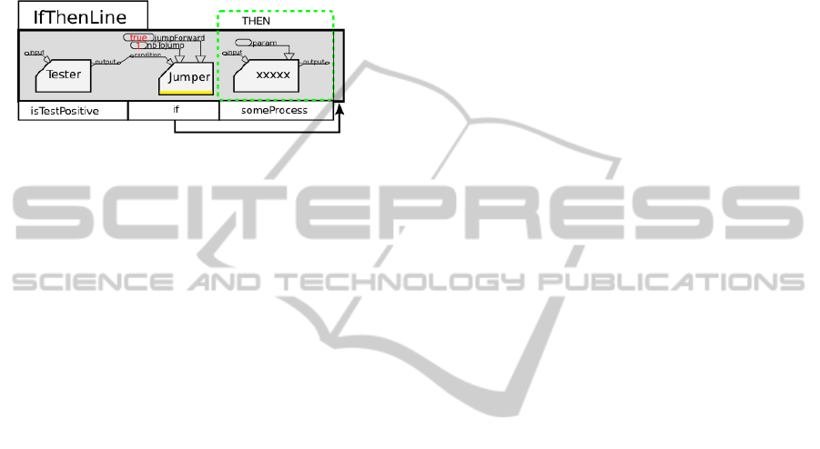
Figure 4: Writing an ”if then” statement.
The Jumper is a first useful example of Control
Flow Component (Figure 4). It implements a
conditional “goto” that sets the next component to
execute by “jumping” forward or backward in the
Processes Line. The Jumper gives the possibility to
implement control structures such as “if then”
statements, but also such as loops when associated
with a “popper” component that pops a single
element from a list. If the jump is defined forward, it
operates an “if then” statement (figure 4). If the
jump is defined backward, it operates a “do while”
loop. For the sake of simplicity in modeling, more
integrated control flow components are also
provided, such as a If statement, and DoWhile,
WhileDo and ForEach loops.
Hence, by associating inter-connectable
components with means to control the execution
flow, and facing the intrinsic complexity of the
modeling of animation with topological
modifications, MORPHO-Map has been designed as
a hybrid system that combines the object oriented
aspects and flexible connectivity of flow
programming with basic sequential programming.
4.3 MORPHO-Map Ide
Researchers, programmers and Computer Animation
designers interact with MORPHO-MAP within a
dedicated Integrated Development Environment.
This IDE is organized in three sub-spaces: a script
editor to support the modeling activity, an output
window that displays both the graphical
representation of the Processes Lines and the patch
of components, and a 3D Open-GL scene window
that displays all of the computed data.
The modeling part of the IDE features seven
predefined Processes Lines, each of them
corresponding to a particular step of the modeling
process. The first two lines are dedicated to the
modeling of the initial state of all the state variables,
and the five others are dedicated to the modeling of
the looped animation process, including modeling of
the topological modifications. These are:
(1) the “Initial Geometry” line, where the
components that build the G-Map and its
geometrical embedding are inserted;
(2) the “Initial Clustering” line, which figures one
Global Clusterer component that defines the
initial clustering;
(3) The “Frame Updaters” line, which updates the
current frame and starts each loop;
(4) and (5) dedicated to the “Modification Process”,
allowing to express the part of the model that
deals with topological modifications and the
update of the state variables in case of a
modification;
(6) The “Animation” line, on which the animation
process is designed;
(7) Finally, an “Export” line, which is, after each
step, in charge of a small amount of post
processing on the geometrical mesh and is able
to export the mesh to various formats, adapted to
the 3D software that may be used for various
renderings.
A typical modeling walk-through in the MORPHO-
Map IDE consists in:
(1) Choosing the motion to input, and, when the user
decides to employ a predefined G-Map instead of
generating it automatically, selecting this G-Map
within the initialization lines.
(2) Designing all the Processes Lines. This mainly
consists in instantiating components, providing
their parameters, and inter-connecting their inlets
and outlets.
(3) Executing the animation – that is launching the
execution of the Processes Lines – and
controlling the results.
Any modeled Processes Line is automatically
stored into a database by the IDE. This allows easy
reuse of pre-modeled parts of the final model, and
sharing within groups of users.
Finally, the MORPHO-Map IDE enables the user
to act at three levels of modeling according to
his/her aim or level of expertise, allowing both
flexibility and progressive learning of the system
and its core features.
The first level consists in editing an existing
model at a basic level: the user only acts on
parameters values, without any change in its
structure (connections, types of components).
The second level consists either in building an
MORPHO-Map-ANewWaytoModelAnimationofTopologicalTransformations
295
entire model or an entire Processes Line from
scratch, or in editing an existing model or Process
Line by changing its structure.
The third level consists in designing a new
component for any component family, and adding it
to the available component series. This is achieved
by means of an XML specification describing the
structure of the component (inlets and outlets names
and types, state variables processed) and a C++ code
snippet describing its algorithm. This third level is of
importance since the question of animation with
topological modifications is an open issue that may
require by principle being able to add new features
and algorithms at the component level.
5 RESULTS
In this section, we illustrate the MORPHO-Map
modeling and simulation processes with animations
of shapes exhibiting topological changes through
three types of models: tearing effects on deformable
garments exhibiting tears and ravels; internal
fissures and clearly-cut cracks in 3D solid objects;
and non realistic imaginary shape metamorphosis.
All the animation functions used in the presented
examples have been produced by Physics-based
particle modeling methods as proposed in (Luciani
et al., 1991) (Evrard et al., 2006).
5.1 A Modeling Process for Tearing
Effects
We illustrate here the modeling process with a
model of fabric exhibiting tearing effects.
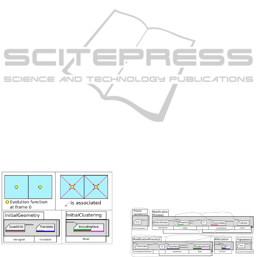
Figure 5: The initial topological state with the Processes
Initialisation Lines corresponding to the initial clustering.
The topological model consists of a grid of quads. In
the example given here, the given point-based
animation, used as an Animation Functions Set, has
been produced by a physically-based particle
animation of a deformable fabric. In this example,
clusters are defined in such a way that each point of
the Animation Functions Set is associated with a
unique quad, and contributes to the animation of the
four vertex of this quad. Figure 5 shows the initial
state with (1) the initial state geometry and initial
clustering (2) their corresponding Initialization Lines
with their two components.
The initial association between the animation
functions set and the G-Map is supported here by a
component called “FloodKeepAtLeast”, which is a
simple example of the topology-based flood
algorithm proposed by (Jund et al., 2012).
The topological modification process consists, at
each frame, in unsewing pairs of quads whenever the
distance of their two associated points in the
animation functions is beyond a given threshold.
Sensing consists in computing the distance
between each relevant pair of points of the
animation functions, and in comparing it to a given
threshold. If the distance exceeds the threshold, the
pair is output by the sensing component, and passed
to Selection. Then, Selection consists in searching,
among the edges of the G-Map, those for which both
vertices are associated with the received pair of
points, i.e. which clusters contain both Animation
Functions. Then, Topological Modification consists
in unsewing the two adjacent faces of this edge.
Finally, Cluster Updating is performed.
The animation process employed is the simplest
that can be used to compute the displacement of
each vertex from its associated animation functions.
When quads are sewn, the displacement of a vertex
shared by several quads is calculated from the
contributions of the animation function associated
with each quad. When they are unsewed, the
displacement of each vertex depends only on the
displacement of its unique associated animation
function.
Figure 6 shows the whole Processes Lines
following the initialization lines presented before
.
Figure 6: The whole Processes lines.
5.2 Tears Effects on Deformable Fabric
Figure 7 (next page) shows the results of the
GRAPP2014-InternationalConferenceonComputerGraphicsTheoryandApplications
296
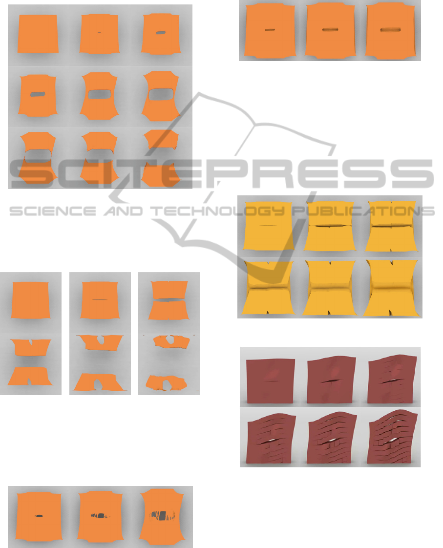
modeling of a tearing effect in a fabric, starting by a
hole with frays, just before the final separation in
two parts.
Figure 7: Tears effect in a deformable fabric: from a hole
to a fracture with frays just before separation.
Figure 8 shows another tearing effect, starting with a
smooth crack on the middle, and forming other tears
on the external sides.
Figure 8: Two tears in a highly deformable fabric.
The images of the MORPHO-Map model shown in
Figure 9 figurate out that this model is able to
exhibit several micro tears surrounding a central
tear, resulting from the propagation of the fabric
deformation within the frailty zone.
Figure 9: Several successive tears resulting from the
propagation of the deformation all along the frailty zone.
Figure 10 shows a type of tear presenting a lot of multiple
very fine serrations or ravels, which appear all along the
tear.
Figure 10: A tear with multiple fine serrations and ravels
along the tear.
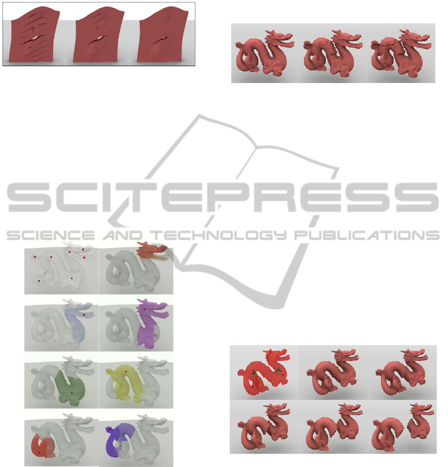
5.3 Cracking Effects on Deformable 3D
Thick Plates
The following figures show the formation of cracks
in deformable 3D thick plates.
Notice the final shapes after the crack, which
result from a soft material in figure 11 and from a
harder material in figure 12.
Figure 11: Cracks in a soft thick 3D plate.
Figure 12: Cracks in a hard thick 3D plate.
Figure 13 shows three variants of a similar
MORPHO-Map model in which we obtain various
types of tearing, from the same Animation
Functions, by changing the topo-geometric
parameters, for instance by decreasing the distance
threshold. We may notice that the material on the
left corresponds to the material used in Figure 12,
MORPHO-Map-ANewWaytoModelAnimationofTopologicalTransformations
297
and it is more brittle than the material on the right.
Figure 13: From left to right, three tearing effects obtained
with the same Animation Functions Set and the same
MORPHO-Map model. Variations are due only to the
changes of the Sensing process parameters.
5.4 Cracking Effects on a Rigid 3D
Object
This paragraph illustrates another type of
MORPHO-map model that differs from the models
of surfaces and plates previously presented in two
aspects: (1) the clustering process, e.g. the mapping
of the animation on the 3D G-Map and (2) the type
of topological modifications.
Figure 14: Clustering and animation mapping for a 3D
object.
The mapping of the animation on the G-Map is
based on the topologically-based flood process
proposed by (Jund et al., 2012). In that case, a very
small number of Animation Functions are associated
with parts of a solid object – the dragon. Figure 14
shows a case with only eight control Animation
Functions and their eight respective zones of
influences. Notice that, similarly to the clustering
employed for the fabric animation presented
previously, zones of influence can overlap. The
dragon used in this example is the final geometrical
meshed object.
Figure 15: Emergence of internal rifts from the clustering
and animation functions shown in Figure 14.
Using this clustering, sensors detect elongations
between each pair of animated points and, according
to the sensed data, the topology of the zone of
influence zone is changed. Results presented in
Figure 15 show how progressive internal rifts are
emerging.
Figure 16 shows another model generating
clearly-cut cracks on a 3D object – here we use the
dragon again. The animation is produced by an
existing Physics-based model, composed of two
tetrahedra, modeled by 4 masses, elastically linked
to each other. Each tetrahedron controls the
movement of a part of the dragon, as shown in
Figure 16-Up-Left. Both tetrahedrons interact
through a cohesive interaction (Darles et al., 2011).
When the cohesive interaction function is disrupted,
the dragon also breaks itself in two pieces. The
motions of each piece remain controlled by the
movement
of its associated tetrahedron.
Figure 16: Modeling crack in a 3D rigid object.
Figure 17 shows other results, with the same
Animation Functions Set as for the dragon cracking,
i.e. produced by the motion of two coupled
tetrahedra. On the upper lines of Figure 17,
tetrahedra are more deformable than for the dragon,
and then, their motions control the fracture of a
deformable bar. On the bottom lines of Figure 17,
the same tetrahedra motions control the
displacements of two rigid objects, a tore and a cone.
Before the tetrahedra dissociation, the movements of
the tore and the cone are elastically linked, whereas
GRAPP2014-InternationalConferenceonComputerGraphicsTheoryandApplications
298
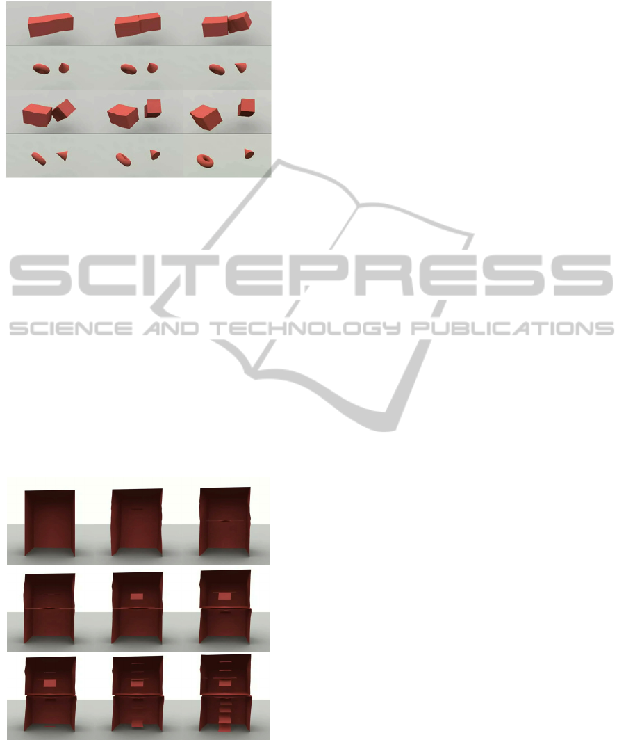
they are free afterwards.
Figure 17: Modeling the animation of other objects with
the same Animation Functions Set. Top lines: the crack of
a deformable bar. Bottom lines: the separation of the
motions of two 3D rigid objects.
5.5 Creating Imaginary Effects
By manipulating the components and the Processes
Lines of the MORPHO-Map environment, it is also
possible to create new evolutionary shapes. Hence,
stimulating the creativity could lead to non-realistic
modeling. Figure 18 shows a deformable box
animated by a previously computed Physics-based
masses-interactions simulation, which
metamorphoses itself into two deformable boxes
with creation of internal deformable sheets. Note
that the motion may remain coherent despite the
metamorphosis of the object.
Figure 18: Physically-based animation of a non realistic
imaginary topological metamorphosis of a deformable
box.
6 CONCLUSIONS
Managing the evolution of the topology in an
animation process is a new challenge in computer
animation. A wide variety of metamorphoses and
transformations may exist, depending on the physics
of the matter but also on the spatial shape of that
matter. Rather than considering an object as a whole,
processing closely its matter and its shapes, we
suggest here to separate both parts. This lead us to
define a more generic modeling process composed
of three stages: (1) generation of motion; (2)
modeling of the topology and its mapping on a
meshed geometrical model; (3) free control of the
transformation of the topology by the motion.
As the transformation and metamorphosis of the
shapes exhibit strong topological modifications, we
propose to introduce an explicit modeling stage
dedicated to topology, before the classical shape
modeling itself. Thus, the topological modifications
are directly handled in this stage by using motion
data extracted from a pre-existing animation. Such
segmentation of the animation process of complex
evolutionary shapes allows modeling any kind of
animated topological transformations in a generic
and modular way. Supported by a modular pipeline
and a graphical IDE, it makes the experimentation of
the modeling of complex phenomena possible by
any kind of programmers or designers.
Finally, we assume that the work presented here
open new ways of modeling and new
experimentations, by anyone. Moreover, with the
development of new ways of programming, many
users other than programmers, interested in
experiencing modeling and animation of complex
shapes, may have in hand, with MORPHO-Map, a
versatile programming tool, not limited to specific
algorithms dedicated to a restricted class of effect.
Our experience with art students who are, nowadays,
very skilled and curious of new types of
programming, makes it possible to say that such
tools will be used in a creative way to imagine
realistic or non-realistic animations.
In addition, the different levels of modeling
allowed by the MORPHO-Map framework
(changing the parameters of a previous MORPHO-
Map structure available in the database, designing a
new MORPHO-Map structure using existing
Processes Lines, programming new MORPHO-Map
components, such as new clustering processes, new
selectors, or new topological modifiers), allow new
users to progressively evolve in the practice of
computer modeling.
A number of evolutions are then possible, to
MORPHO-Map-ANewWaytoModelAnimationofTopologicalTransformations
299

provide a more user-centered modeling tool,
alongside dedicated algorithms and interactive user
interfaces that are less expandable. Our main goal is,
from now on, to go toward new types of
programming and modeling of such complex
phenomena, such as visual or creative programming.
ACKNOWLEDGEMENTS
These research works have been supported by the
French National Research Agency under the contract
ANR-09-CONT-007 named DYNAMé, the French
Ministry of Research and the French Ministry of
Culture.
REFERENCES
Bao, Z., Hong, J.M., Teran, J. and Fedkiw, R., 2007.
Fracturing Rigid Materials. In IEEE Transactions on
Visualization and Computer Graphics-13, pp 370-378.
Bézin, R., Crespin, B., Skapin, X., Terraz, O., Meseure, P.,
2011. Topological Operations for Geomorphological
Evolution. In Proceedings of VRIPHYS 2011.
Carter, B.J., Ingraffea, A.R., Bittencourt, T.N., 1995
(reprint 2008). Topology-controlled Modeling of
Linear and Nonlinear 3D Crack Propagation in Geo-
Materials. In Fracture of Brittle, Disordered
Materials, G. Baker and B.L. Karihaloo Eds, Taylor &
Francis Pub.
Chen X., Lienhardt P, 1992. Modeling and programming
evolutions of surfaces. In Computer Graphics Forum,
Vol. 2, no. 5.
CGoGN http://cgogn.u-strasbg.fr/Wiki/index.php/
CGoGN.
Darles, E., Kalantari, S., Skapin, X., Crespin, B., Luciani,
A., 2011. Hybrid physical – topological modeling of
physical shapes transformations. In Proc. of CASA
2011 - Digital Media and Digital Content
Management, pp. 154–157.
Desbenoit, B., Galin, E., Akkouche, S. 2005. Modeling
Cracks and Fractures. In The Visual Computer
(Proceedings of Pacific Graphics). 21(8-10), 717-726.
Desbrun, M., Cani-Gascuel, M-P., 1995. Animation of soft
substances with implicit surfaces. In SIGGRAPH, ser.
Comput. Graph., pp. 287–290.
Evrard, M., Luciani, A., Castagné, N., 2006. MIMESIS :
Interactive interface for mass-interaction modeling. In
Proc. of CASA 2006, pp. 177–186.
Fléchon, E., Zara F., Damiand, G., Jaillet, F. 2013. A
generic topological framework for physical simulation.
In proceedings of the 21st International Conference on
Computer Graphics, Visualization and Computer
Vision, pp 104-113.
Glondu, L., Muguercia, L., Marchal, M., Bosch, C.,
Rushmeier, H., Dumont, G., Drettakis, G. 2012.
Example-Based Fractured Appearance. In
Eurographics Symposium on Rendering 2012. Vol.
31(4).
Glondu, L., Marchal, M., Dumont, G., 2013. Real-Time
Simulation of Brittle Fracture using Modal Analysis.
In IEEE Transactions on Visualization and Computer
Graphics, Vol. 19(2), pp.201-209.
Habibi A., Luciani A., 2002. Dynamic particle coating. In
Transactions on Visualization and Computer
Graphics. Vol. 8. pp. 383-394.
Irving, G., Guendelman, E., Losasso, F., Fedkiw, R., 2006.
Efficient Simulation of Large Bodies of Water by
Coupling Two and Three Dimensional Techniques. In
Proc. of SIGGRAPH 2006, ACM TOG n°25, pp. 805-
811.
Jund, T., Allaoui, A., Darles, E., Skapin, X., Meseure, P.,
Luciani, A., 2012. Mapping volumetric meshes to
point-based motion models. In Proc. of VRIPHYS
2012, pp. 11–20.
Lienhardt, P. 1994. N-dimensional generalized
combinatorial maps and cellular quasi-manifolds. In
Int. J. Comput. Geom. Appl., vol. 4, no. 3, pp.275–324.
Losasso, F., Talton, J., Kwatra, N., Fedkiw, R., 2008.
Two-way Coupled SPH and Particle Level Set Fluid
Simulation. In IEEE Transactions on Visualization
and Computer Graphics, n° 14, pp. 797-804.
Luciani, A., Evrard, M., Couroussé, D., , Castagné, N., ,
Cadoz, C., Florens, J-L., 2006. A basic gesture and
motion format for virtual reality multisensory
applications. In Proc. of the First International
Conference on Computer Graphics Theory and
Applications (GRAPP), pp. 349–356.
Luciani, A., Jimenez, S., Florens, J-L., Cadoz, C., Raoult,
O. 1991. Computational physics: a modeler-simulator
for animated physical objects. In Proceedings of
EUROGRAPHICS’91, pp. 425–436.
Molino, N., Bao, Z. and Fedkiw, R., 2004. A Virtual Node
Algorithm for Changing Mesh Topology During
Simulation. In Proceedings of SIGGRAPH 2004,
ACM TOG n°23, pp385-392.
Meseure, P., Darles, E., Skapin, X., 2010. A Topology-
Based Mass/Spring System. In Proc. of CASA 2010.
MOKA. http://sourceforge.net/projects/moka-modeller/
Nayrolles, B., Touzot, G., Villon, O. 1992. Generalizing
the finité element method : Diffuse approximation and
diffuse elements. Computational Mechanics - 10, pp
307-318.
O’Brien, J.F., Bargteil, A.W., Hodgins, J.K., 2002.
Graphical modeling and animation of ductile fracture.
In Proceedings of SIGGRAPH 2002, pp. 291–294.
Pauly, M., Keiser, R., Adams, B., Dutré, P., Gross, M.,
Guibas, L.J., 2005. Meshless animation of fracturing
solids. In Proceedings of SIGGRAPH 2005, pp 957-
964.
Prusinkiewicz, P., Lindenmayer, A., 1990. The
algorithmic beauty of plants: the virtual laboratory.
Springer Verlag.
Wojtan, C., Thurey, N., Gross, M., Turk, G., 2009.
Deforming meshes that split and merge. In ACM
Transactions on Graphics, vol. 28, no. 3, pp. 76-86.
GRAPP2014-InternationalConferenceonComputerGraphicsTheoryandApplications
300
