
Accurate X-corner Fiducial Marker Localization in Image
Guided Surgery (IGS)
Thomas Kerstein
1
, Hubert Roth
2
and Jürgen Wahrburg
1
1
Center for Sensor Systems (ZESS), University of Siegen, Paul-Bonatz-Straße 9-11, 57076 Siegen, Germany
2
Institute of Control Engineering, University of Siegen, Hölderlinstr. 3, 57076 Siegen, Germany
Keywords: X-corner, Fiducial Marker, Optical Localization, Image Guided Surgery (IGS), Corner Detection.
Abstract: In this paper a novel approach for reliable detection and accurate localization of X-corner fiducial markers
is presented, which is particularly designed for Image Guided Surgery (IGS). The key idea is to combine
two meaningful basic topological characteristics to one boosted filter providing adequate detection reliabil-
ity and localization accuracy. Additionally and in contrast to conventional, retroreflective planar or spherical
markers, X-corner fiducials facilitate not only position measurements with high precision but provide addi-
tional orientation information for improving distinction of multiple fiducials arranged within a geometrical
reference structure. Experiments reveal robustness to considerable perspective distortion as well as invari-
ance to illumination changes. Furthermore the presented approach offers high computational efficiency and
a high level of flexibility for application-specific system design.
1 INTRODUCTION
Synthetic landmarks in form of X-corners (Figure 1,
2) provide high quality reference points for various
visual localization tasks in photogrammetry and
computer vision, most notably in context of camera
calibration and crash tests in the automotive sector.
As a matter of principle, X-corner fiducials can
be localized with high precision even if only a small
area around the centre is visible. In contrast, accu-
rate localization using planar or spherical markers
requires the total marker area to be visible and free
of contamination as the position is determined by
computing the centre of this area. Further benefits
are simple manufacturing by printing and mounting
just by sticking.
In this paper we mainly focus on detection and
localization of X-corner fiducials with regard to
specific demands of Image Guided Surgery (IGS).
Usually at least three markers are combined to form
a discrete reference body (DRB) which is used to
determine position and also orientation of an object,
using Stereo Vision technique. Due to identical ap-
pearance of each marker, a common DRB can solely
be identified by regarding the distances between all
associated markers as the only relevant distinctive
feature. Therefore a unique geometry constraint has
to be considered for DRB design. In this regard X-
corners can help to reduce this limitation by provid-
ing an additional distinctive feature in terms of ori-
entation of the edges between bright and dark sec-
tors in conjunction with the arrangement of these
sectors with respect to the centroid. Thus, X-corners
strongly facilitate the design of customized DRBs.
The main contribution consists in the combina-
tion of two discriminative topological features to an
efficient operator which offers reliable detection and
accurate localization added by the reconstruction of
the edge orientations. The method is proposed to be
embedded into a proprietary optical 3D localization
framework combined with a navigated surgical robot
assistance system which along with the desired sys-
tem modularity implies the following demands:
Access to all relevant parameters allowing for
a high level of flexibility instead of the black
box character of a commercial digitizing sys-
tem such as "MicronTracker®" by Claron
Technology Inc. (Gibbons, 2011).
Real time capability due to control oriented
demands of a navigated robot system.
Accuracy in the sub-millimetre range accord-
ing to general requirements in IGS.
Rapid design of customized DRBs allowing
for reliable identification combined with less
471
Kerstein T., Roth H. and Wahrburg J..
Accurate X-corner Fiducial Marker Localization in Image Guided Surgery (IGS).
DOI: 10.5220/0004751904710478
In Proceedings of the 3rd International Conference on Pattern Recognition Applications and Methods (ICPRAM-2014), pages 471-478
ISBN: 978-989-758-018-5
Copyright
c
2014 SCITEPRESS (Science and Technology Publications, Lda.)

restrictive design rules / limitations regarding
the unique geometry constraint.
General approach for facilitating the use of
different stereo camera configurations.
Robustness to significant perspective distor-
tion and large variation of global and local il-
lumination conditions, e.g. due to partial shad-
ing.
Providing an extendable and universal exper-
imental platform for evaluation.
2 RELATED WORK
2.1 Image Guided Surgery (IGS)
Optical 3D localization systems provide the founda-
tion for applications in IGS to permanently acquire
the spatial position of surgical instruments with re-
gard to the patient's anatomy. In order to provide this
functionality, both the patient and all surgical tools
are typically equipped with fiducial based DRBs
which are observed by a stereo camera as depicted in
Figure 1 for an Image Guided Biopsy application.
Figure 1: Typical setup of stereo vision-based 3D localiza-
tion for surgical interventions shown for an Image Guided
Biopsy scenario. Both patient and surgical tools (here the
biopsy needle) are equipped with DRBs consisting of at
least three fiducial markers which are detected and local-
ized within both images of the stereo camera. By applying
stereo triangulation, the objects' positions and orientations
(represented by associated coordinate frames) are recon-
structed. Thus, they can be spatially related to one another.
The processing pipeline for the optical 3D localiza-
tion of a DRB basically consists of the following
four steps:
1. Detection and 2D localization of single mark-
ers in both images of the stereo camera
2. 3D reconstruction of the 2D positions comput-
ed in step 1 applying stereo triangulation
3. Distance-based identification of the reference
body geometry by assigning the markers to the
DRB
4. Computation of position and orientation of the
DRB using an appropriate registration method
This paper focuses exclusively on the 2D detec-
tion and localization of the fiducial markers in the
first step, which has the most significant impact on
the overall localization result. Conversely, all other
steps which are provided by well-proven standard
methods like stereo triangulation and registration
immediately depend on the accurate 2D localization.
2.2 X-Corner Detection
and Localization
Due to broad utilization of X-corners, especially for
camera calibration using planar chessboards, a lot of
research has been put into methods for detection and
localization of which only a minor subset can be
addressed here. Many approaches are particularly
designed for camera calibration, which due to the
regular structure of chessboards can benefit both
from additional context information (equal corner
distances) and consistent illumination conditions
across the overall chessboard area. Unfortunately
this does not apply to general fiducial localization.
First of all, there is a broad class of more or less
classical methods intended for general rather than
for particular X-shaped corner detection. These in-
clude, among others, the Moravec algorithm (Mora-
vec, 1980), being one of the first approaches, the
Förstner (Förstner, 1987) or the SUSAN corner de-
tector (Smith, 1997) to name only a few of them.
Probably one of the most commonly used method
within this class is the Harris Corner Detector (Har-
ris, 1988). This method establishes a corner response
function where corners are located at local maxima.
However, as these locations just like those obtained
by other general corner detection methods in general
do not agree with X-corner centroids, these methods
are not very appropriate for X-corner localization.
An enhanced method accounting for distinctive
X-corner characteristics, primarily symmetry con-
straints is presented by Zhang et al. (Zhang, 2009).
They propose a "quarter operator" intended for cam-
era calibration. Symmetry, variance and intensity
ICPRAM2014-InternationalConferenceonPatternRecognitionApplicationsandMethods
472

distribution regarding each pixel are incorporated as
additional constraints. Even though the approach is
similar to the one presented here, their variance op-
erator does not apply a differential principle like the
skew symmetric operator in our approach, which
thus offers inherently larger robustness to varying
illumination conditions and perspective distortion.
A common and obvious strategy for X-corner lo-
calization is provided by the following two-stage
method: In the first stage corners are localized with
pixel accuracy by a conventional corner detector like
(Harris, 1988). In the second step localization is
refined to subpixel accuracy by fitting a quadratic
function to the interpolated intensity profile within
close-up range around these preliminary corners and
computing their extrema (Jain, 1995). However
resulting from the first stage the close-up window
might be decentred several pixels to the true centroid
and least square fitting is generally sensitive to out-
liers. Thus surface fitting may lead to significant
localization errors. For increasing accuracy and pro-
cessing speed, Lucchese et al. (Lucchese, 2002)
propose an alternative method without surface fitting
by computing first and second order partial image
derivatives on the local intensity profile and compu-
ting the extrema by morphological shrinking. How-
ever this method is not capable to capture the char-
acteristic X-corner topology with the same quality as
achieved by a particularly designed algorithm.
A more recent approach is proposed by Chen et
al. (Chen, 2005), who apply a second order Taylor
polynomial describing the local intensity profile
around a preliminary corner. In (Zhao, 2011) an
automated X-corner detection algorithm (AXDA) is
presented where an X-corner is localized as the in-
tersection of straight lines which have been fitted
into the local intensity profile.
A further category of methods is formed by tem-
plate-based approaches such as presented by (Arca,
2005) and (Xu, 2011) which is, just like ours, in-
tended for surgical robot applications in the style of
(Gibbons, 2011) rather than for camera calibration.
Finally, to provide a last method, recently a nov-
el approach based on multiple weighted steerable
matched filters (Mühlich, 2012) has been presented.
In conclusion, despite of the multitude of availa-
ble approaches for X-corner detection and localiza-
tion, each of those, listed here either exhibit a lack of
robustness to variation of illumination conditions
and perspective distortion and/or offers insufficient
localization accuracy. All in all, this highly moti-
vates the development of an X-corner detector which
meets these crucial demands for IGS applications.
3 A NOVEL APPROACH FOR
X-CORNER LOCALIZATION
Initially some important parameters of an X-corner
fiducial marker should be defined.
Centroid
,
: point of intersection be-
tween the bright and dark areas.
Inward edges
,
with∈
1,2
: edges be-
tween bright and dark sectors with a bright
sector on its left and a dark sector on its right
side, as seen from the centroid
Outward edges
,
with∈
1,2
: com-
plements of inward edges, with a dark sector
on its left and a bright sector on its right side,
as seen from the centroid.
Figure 2: Topology of an X-corner fiducial marker, shown
in the reference formation.
The processing pipeline of our approach com-
prises three main steps: (1) preselection of candidate
fiducials, (2) accurate subpixel localization of the
centroids and (3) determination of edge orientations
as described explicitly in the following sections.
3.1 Preselection of Candidate Fiducials
As initial step Harris Corner Detection (Harris,
1988) is applied to the input image to identify cor-
ners approximately (usually within a range of few
pixels around the true centroid). This step leads al-
ready to massive data reduction for further pro-
cessing. Afterwards the number of wrong candidates
is further reduced by applying intensity-based seg-
mentation to a region of interest (ROI) centred on
each corner. For a valid X-corner at least two dis-
tinct regions have to be identified. Finally the pre-
liminary centroid is shifted and the ROI is re-centred
to the balance point of the segmented regions.
3.2 Centroid Localization
with Subpixel Accuracy
From a geometrical point of view, the shape of an X-
corner can be approximated by a hyperbolic parabo-
loid with the -axis parameterizing the pixel intensi-
AccurateX-cornerFiducialMarkerLocalizationinImageGuidedSurgery(IGS)
473
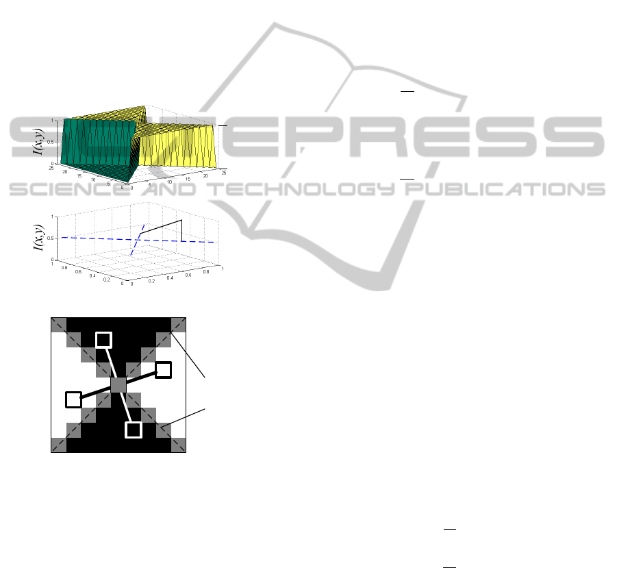
ty
,
. For an “ideal”, unrotated X-corner the
hyperbolic paraboloid takes a degenerated form as
depicted in Fig. 3a. In this case any hyperbola in a
section plane parallel to the --plane consists only
of their asymptotes being orthogonal to each other
(degenerated equilateral hyperbola) and intersecting
in the centroid of the X-corner given by the form:
⟹
.
(1)
Thus, given the centroid the two following charac-
teristics (cf. Figure 3b) can be derived:
1. Two-fold rotational symmetry with respect to
the centroid (central symmetry).
2. Axial skew-symmetry (anti-symmetry) with
respect to the asymptotes of any sectional hy-
perbola parallel to the --plane.
Figure 3: X-corner modelled as a hyperbolic paraboloid.
(a) Degenerated form (top) and asymptotes of the sectional
hyperbola in plane z0.5(bottom). (b) Illustration of
mathematical constrains of X-corners with respect to
individual pixels (A, ..., D) with a given intensity Ix,y.
3.2.1 Combination of Discrete Symmetry
Functions
For precise calculation of the centroid to pixel accu-
racy from a given input image two discrete func-
tions,
(central symmetry) and
(skew-
symmetry) are derived from the developed con-
strains which both of them exhibit a differential
computation scheme. After these functions have
been applied to each pixel in the respective ROI, the
centroid corresponds to the position of a global ex-
tremum related to each function respectively.
For increasing detection reliability and localiza-
tion accuracy due to noise, the functions operate on
groups of pixels rather than individual pixels as
depicted in Figure 3b. Given a quadratic image re-
gion of pixels (21,1) the dis-
crete function operators
∈
and
∈
are formulated as follows:
Central symmetry:
,
1
|
,
,
,
|
(2)
Axial skew-symmetry:
,
1
|
,
,
,
,
,
|
(3)
Regarding
, the position of the centroid corre-
sponds to the position of its global minimum
min
,
, in the ROI, whereas considering
,
it corresponds to the position of its global maximum
max
,
,.
Since it is inconvenient for computation to re-
gard both functions separately, they are combined to
the overall objective function
∈
in which
the centroid is consistently identified at the position
of the global maximum:
0,
,
(4)
Here
and
are the normalized discrete func-
tions with respect to their arithmetic averages
and
respectively:
,
1
,
(5)
,
1
,
(6)
Since the centroid of a valid X-corner always
corresponds to a distinctive peak far above the aver-
age
(in general:max
,
3
), the maximum
output of
is further utilized for indicating and
rejecting wrong corner candidates. If it is beyond a
given threshold ;13
the centroid
A
B
C
D
(a)
1.) I(A) – I(B) = 0 ˄ I(C) – I(D) = 0
2.) ǀI(A) + I(B) - (I(C) + I(D))ǀ = 2(I
1
–I
0
)
(b)
Asymptotes
y
y
c
I
1
I
0
x
x
I
0
I
0
I
1
I
1
Asym-
ptotes
ICPRAM2014-InternationalConferenceonPatternRecognitionApplicationsandMethods
474
,
is computed with subpixel accuracy as
the weighted average of
across the region:
,
∑
,
∑
,
,
∑
,
∑
,
(7)
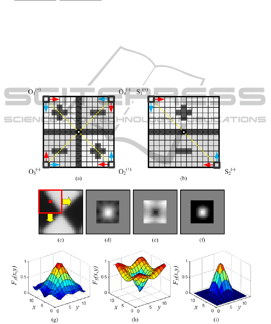
3.2.2 Function Representation in Form of
Template Masks
and
can be conveniently represented in form of
template masks being applied to an input image.
These masks virtually consist of “positive” and
“negative” areas. Concerning
one pair of opposite
pixels is involved in each step of calculation where-
as concerning
two pairs of opposite pixels are
involved. The result of each calculation step is the
difference between respective pixel values in “posi-
tive” and “negative” regions.
Both masks and the effect of applying these
masks to an example input image of an X-corner
fiducial are depicted in Figure 4.
3.3 Determination of Edge Orientation
Due to the two-fold rotational symmetry with re-
spect to its centroid, the edge orientations of an X-
corner are unique only up to a rotation of 180 de-
grees. Thus, edge orientation does not provide a
unique measure but largely helps as an additional
distinctive feature to reduce the risk of misidentifica-
tion of a particular reference body configuration
which is used during a surgical intervention.
Figure 4: Template masks for X-corner fiducial localization and results. (a) Template mask for F
. (b) Template mask for
F
. (c) Applying a mask to an input image. (d) Output of F
. (e) Output of F
. (f) Final output of F
. (g) – (i) 3D-surface
representation of function outputs of F
, F
and F
normalized to [0,1].
AccurateX-cornerFiducialMarkerLocalizationinImageGuidedSurgery(IGS)
475
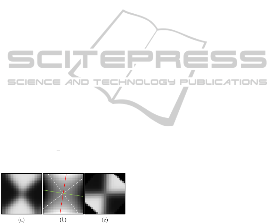
The edge orientations are determined by computing
the orientation of the main axes of a hyperbolic pa-
raboloid fitted to the smoothed close-up view
around the centroid (Figure 5a) by solving the fol-
lowing objective function (Equation 8) in least
squares sense (Jain, 1995):
min
,…,
‖
,
‖
(8)
Here
,…,
are the (unknown) coefficients of
the implicit form of a hyperbolic paraboloid and
,
is the pixel intensity at a given position
, (Figure 5b).
In order to account for hyperbolic paraboloids ra-
ther than for elliptical paraboloids, the discriminant
∆ must be constrained to∆
0. Howev-
er, since we already know the shape, the discrimi-
nant can be ignored.
Afterwards the rotation angle between the
transverse axis (semi-major axis) and the -axis can
be computed:
tan2
2
(9)
Since it is not specified if the transverse axis co-
incides with the bright or the dark sectors, the com-
parison of and must be analyzed as an additional
criterion. Finally the rotation angle ϕ
of the fiducial
relative to its reference orientation can be computed
and thus the edge correspondences for e
,
and
e
,
can be derived (c.f. Figure 5c):
4
,
4
,
(10)
Figure 5: Determining edge orientations of an X-corner
fiducial: (a) Input image (ROI) after Gaussian smoothing.
(b) Resulting hyperbolic paraboloid obtained by linear
least squares fitting (asymptotes: white dashed lines, semi-
major axis: red solid line, semi-minor axis: green solid
line). (c) Fiducial rotated by ϕ
to its reference orientation.
4 EXPERIMENTAL RESULTS
In this section, the performance of the proposed
approach is evaluated in terms of processing speed,
localization accuracy with respect to different dis-
tances and viewing angles and robustness as signifi-
cant criterions for IGS. The experiments were per-
formed on an Intel Core™2 Quad @2.5GHz CPU
using a stereo camera of type PointGrey Bumblebee
BB2-03S2M-60 (Point Grey, 2013) with a baseline
of 120 mm, a focal length of 6 mm, a field of view
of 43 degrees and a resolution of 640480 pixels.
4.1 Processing Speed
In the first experiment the runtime performance is
analyzed. For this purpose 1000 samples are record-
ed and the average time consumption is evaluated.
The by far most significant portion of processing
time is required by Harris Corner Detection in the
preselection step, explicitly over 10 ms for the given
image resolution. However to our experience it is
sufficient to execute corner detection on a
downscaled version of the input image of half width
and height respectively. Thus, time consumption of
this step can be reduced by a factor of 4 to 2.52 ms.
All other steps amount only 13% in total of the
overall processing time, explicitly 0.16 ms for cen-
troid computation and 0.21 ms for orientation com-
putation, summing up to an average time consump-
tion of 2.89 ms in total for the complete detection
and localization of an X-corner fiducial marker.
4.2 Localization Accuracy
In the next experiment, the effect of varying marker
positions and orientations on the 2D as well as the
3D localization accuracy is evaluated.
4.2.1 2D-Localization Accuracy
First of all the 2D localization error, defined as the
Euclidian distance between the measured and the
target position of a fiducial is utilized and regarded
as a function of its position and orientation.
Since it is hardly possible to acquire the ground-
truth 2D marker-position with respect to the image
coordinate system of the camera using real image
data, the localization accuracy is examined by simu-
lation. For this purpose, a single camera module of
the stereo camera is modelled by using OpenGL
according to the actual camera parameters.
A square X-corner fiducial with a side length of
24 mm is placed within the virtual scene wherein the
pose is provided externally by the system. The refer-
ence pose is chosen on the optical axis at a distance
of 500 mm in front of the camera and without any
rotation. To allow for a reproduction as realistic as
ICPRAM2014-InternationalConferenceonPatternRecognitionApplicationsandMethods
476
possible, both additive and multiplicative pixel noise
(amplifier and shot noise) is added to the scene.
In order to provide a reference to state-of-the-art
X-corner localization, the measurements are also
performed with the "quarter operator" (QO) present-
ed in (Zhang, 2009) (c.f. 2.2) which follows a simi-
lar approach as the one presented in this paper.
All parameters are varied individually in order to
expose distinctive characteristics and progressions.
Position components are varied within steps of
1 mm, while rotation angles are varied within steps
of one degree. The results are shown in Figure 6.
Here always a number of samples (50 for and 10
for all other dimensions) are averaged together to
achieve a better illustration.
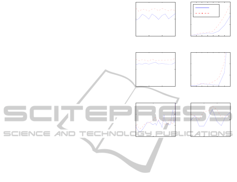
Referring to these measurements, the localization
error is always much less than one pixel. Regarding
, and, the marker is detected in the whole range
with a mean localization error of even less than 0.04
pixels. Regarding the distance between camera and
marker, reliable detection is provided up to at least
1800 mm. The detection range is primarily limited
by the focus range of the camera and the projected
size of the marker on the imager, which must not be
less than 99 pixels. The smaller the mask, the
larger is the maximum measurement distance but the
smaller is the available resolution. For the given
configuration the optimal scale of the fiducial rela-
tive to the imager of the camera is at about 500 mm.
Regarding pan and tilt , reliable detection is
provided up to at least 50 degrees. Here the localiza-
tion error does not exceed 0.1 pixels in this range,
whereas beyond, measurement uncertainties due to
perspective distortion become noticeable.
Our approach outperforms the quarter operator in
almost the entire measuring range, especially in
presence of large perspective distortion (,) where
localization most notably benefits from the differen-
tial principle of the skew symmetric operator.
4.2.2 3D-Localization Accuracy
For providing a more practice-oriented accuracy
measure for IGS, additionally the 3D localization
error is evaluated using the real stereo camera. In
contrast to the 2D localization error, this is achieved
as the mean deviation between known and measured
distances of 25 markers distributed on a grid (with
well known distances) to the particular one which is
placed at the position in question. The distance to
the camera is varied from 200 to 1200 mm. For de-
termining orientation the grid is accordingly rotated.
Here the distance deviation is always less than
0.5 mm. Regarding , and , it is even less than
Figure 6: Comparison of the 2D localization error of an X-
corner fiducial subject to its position (left) and orientation
(right), between the computation with the proposed ap-
proach (FX; solid line) using
and the "quarter operator"
(QO; dashed line) presented in (Zhang, 2009).
0.1 mm within the whole range, whereas at a dis-
tance of 1000 mm, it has been measured with
0.45 mm. Regarding and the distance deviation
is below 0.25 mm in the range of 0 to 50 degrees.
4.3 Robustness
Finally robustness of detection and localization is
analysed by positioning fiducials within a wide dis-
tance and orientation range combined with strongly
varying illumination conditions. 32 successful re-
sults for poor image quality are shown in Figure 7.
5 CONCLUSIONS
We have presented a novel technique for reliable
detection and accurate localization of X-corner fidu-
cial markers with regard to specific demands of IGS
providing the perspective to be combined with a
navigated surgical robot assistance system. For de-
tection and localization fundamental topological
features are combined to an efficient detector.
0 40 80 120
0
0.02
0.04
x
[mm]
2D error [pixel]
0 10 20 30 40 50 60 7
0
0
0.2
0.4
0.6
[°]
0 40 80 120
0
0.02
0.04
y
[mm]
2D error [pixel]
0 10 20 30 40 50 60 7
0
0
0.2
0.4
0.6
[°]
200 1000 2000
0
0.05
0.1
0.15
z
[mm]
2D error [pixel]
0 30 60 9
0
0
0.02
0.04
[°]
FX
QO
[mm] [°]
[mm] [°]
[mm] [°]
2D-error [pixel]
2D-error [pixel]
2D-error [pixel]
AccurateX-cornerFiducialMarkerLocalizationinImageGuidedSurgery(IGS)
477
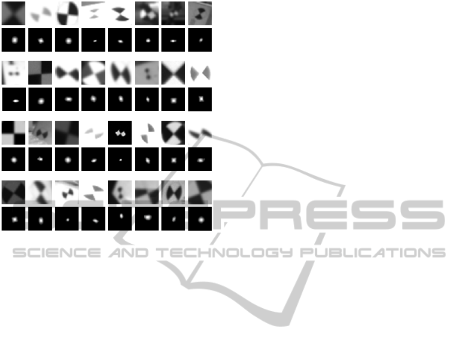
Figure 7: Selection of 32 different samples of X-corner
fiducials from real-world scenes and corresponding pro-
cessing results (ROI size: 2727pixels). Upper rows:
Sample images (Input images). Lower rows: Results of
applying
to the input images. Note the large variations
regarding both illumination and perspective distortion.
Major advantages include highly flexible system
design possibilities in conjunction with real time
capability and localization accuracy in the subpixel /
sub-millimetre range. Further benefits are robustness
to large variation of both illumination conditions and
perspective distortion. The additional determination
of the edge orientations of an X-corner provides an
additional distinctive feature for improving detection
reliability of a certain reference body template and
therefore attenuates the restrictive unique geometry
constraint of reference bodies consisting of conven-
tional fiducial markers used for IGS. For that reason
and due to simple mounting of X-corner fiducials
just by sticking on an object, the presented approach
is predestined for rapid and flexible DRB design.
In future research the corresponding advantages
for simpler patient tracking will be investigated.
REFERENCES
Arca, S., Casiraghi E., Lombardi, G., 2005. Corner Local-
ization in chessboards for camera calibration. IADAT-
micv2005, Madrid.
Chen, D., Zhang, G., 2005. A New Sub-Pixel Detector for
X-Corners in Camera Calibration Targets. In Proceed-
ings of WSCG (Short Papers), pp. 97-100.
Förstner, W., Gülch, E., 1987. A Fast Operator for Detec-
tion and Precise Location of Distinct Points, Corners
and Centres of Circular Features. In ISPRS Intercom-
mission Workshop, Interlaken, pp. 149-155.
Gibbons, M., 2011. In Need of a Keen Eye - Stereo Vi-
sion-Based Optical Tracking Yields New Surgical
Tools. Inspect-online - Imaging and Machine Vision,
http://www.inspectonline.com. Vancouver.
Harris, C., Stephens, M., 1988. A combined corner and
edge detector. In Proceedings of the Fourth Alvey Vi-
sion Conference. Manchester, pp. 147-151.
Jain, R., Kasturi, R., Schunck, B.G., 1995. Machine Vi-
sion, McGraw-Hill, Inc., New York, NY.
Lucchese, L., Mitra, S. K., 2002. Using Saddle Points for
Subpixel Feature Detection in Camera Calibration
Targets. In Proceedings of the 2002 Asia Pacific Con-
ference on Circuits and Systems, Singapore, pp. 191-
195.
Moravec, H., 1980. Obstacle Avoidance and Navigation in
the Real World by a Seeing Robot Rover. Tech. Re-
port CMU-RI-TR-3, Carnegie-Mellon University, Ro-
botics Institute.
Mühlich, M., Friedrich, D., Aach, T., 2012. Design and
Implementation of Multi-Steerable Matched Filters.
IEEE Transactions on Pattern Analysis and Machine
Intelligence (PAMI), Vol. 34, Issue 2, pp. 279-291.
Point Grey Research, 2013. Stereo vision Bumblebee2 web
page: http://www.ptgrey.com/products/bumblebee2,
last visited on 2013-09-20.
Smith, S. M., Brady, J. M., 1997. SUSAN – a new ap-
proach to low level image processing. International
Journal of Computer Vision, Vol. 23, No. 1, pp. 45–
78.
Xu H., Sun, B., 2011. X-corner detection based on Seg-
ment Test Applied in optical pose tracking system. In-
ternational Symposium on Bioelectronics and Bioin-
formatics (ISBB), Suzhou, pp. 162-165.
Zhang, S., Guo, C., 2009. A Novel Algorithm for Detect-
ing both the Internal and External Corners of Checker-
board Image. ETCS '09, First International Workshop
on Education Technology and Computer Science, Wu-
han, pp. 975-979.
Zhao, F., Wei, C., Wang, J., Tang, J., 2011. An Automated
X-corner Detection Algorithm (AXDA). In Journal of
Software, Vol. 6, No. 5, pp. 791-797.
ICPRAM2014-InternationalConferenceonPatternRecognitionApplicationsandMethods
478
