
Program-based and Model-based PLC Design Environment for
Multicore FPGA Architectures
Christoforos Economakos
1
, Michael Skarpetis
1
and George Economakos
2
1
Technological Educational Institution of Sterea Ellada,
Department of Automation Engineering, GR34400 Psahna, Evia, Greece
2
National Technical University of Athens, School of Electrical and Computer Engineering,
Microprocessors and Digital Systems Laboratory, Heroon Polytechniou 9, GR15780 Zografou, Athens, Greece
Keywords:
Digital Control, PLCs, FPGAs, High-level Synthesis.
Abstract:
Digital design has been growing rapidly during the last years, offering advanced implementation solutions for
a diversity of appliances and instruments, integrating different sensors and actuators. This has a great impact
on embedded automation, where traditional Programmable Logic Controllers (PLCs) have been gradually re-
placed by high performance Embedded Controllers, Digital Signal Processor (DSP) chips and, more recently,
power efficient Field Programmable Gate Arrays (FPGAs). Such new implementation platforms bring together
efficient design methodologies, like model-based design and high-level or C level program-based design. In
their turn, new design methodologies are accompanied by new design technologies like Intellectual Property
(IP) based design and High-Level Synthesis (HLS). This paper presents a design environment that utilizes
program-based and model-based design, for the development of PLC applications. Specifically, a tool flow is
constructed that supports either the design of new control algorithms or the translation of existing algorithms
into C. Then, HLS and FPGA implementation tools are adopted, to implement the selected algorithms as mul-
ticore, embedded designs, offering performance improvements and hardware utilization efficiency. Overall,
the proposed methodology and underlying tool flow support a novel high productivity prototyping platform
for digital control applications, with very promising future extension capabilities.
1 INTRODUCTION
Modern industrial control systems need to comply to
different requirements to make a high and fast mar-
ket impact. From the designer’s point of view, all
requirements can be summarized into two key fac-
tors: improve quality (in terms of performance, re-
source usage, power dissipation, etc.) and reduce
time-to-market. The first step in achieving these
goals is the adoption of digital over analog con-
trol methodologies, accompanied by efficient devel-
opment environments (Monmasson et al., 2011). Dig-
ital control can be performed with common microcon-
trollers, Digital Signal Processor (DSP) controllers,
or Field Programmable Gate Arrays (FPGAs). While
DSPs generally include special purpose computa-
tional hardware to improve performance, like floating
point coprocessors or multiply and accumulate ALUs,
and fewer peripherals than common microcontrollers,
they can be considered to belong to the same family
of development platforms. With this family, appli-
cations are written most of the times in C/C++ and
pass through a number of powerful tools like cross-
compilers, linkers, debuggers and simulators, to meet
design constraints.
Recently, the technological advances in FPGA de-
vices, offering hundreds of GFLOPs with maximum
power efficiency, has established a second powerful
development family. FPGAs have been proposed as
an implementation platform between hardware and
software. They consist of specially designed hard-
ware modules connected with efficient circuit switch-
ing interconnections, offering hardware-like perfor-
mance and software-like flexible, dynamic reconfig-
uration. FPGA programming is based on Hardware
Description Languages (HDLs) like VHDL or Ver-
ilog. HDL programming require domain specific
knowledge that can keep non-expert designers away
and impose a negative impact on productivity.
To improve designer productivity and reduce
time-to-market, modern design techniques like High-
Level Synthesis (HLS), Electronic System Level (ESL)
design or, in simpler terms, C based hardware de-
sign can be adopted. HLS, ESL and C based
726
Economakos C., Skarpetis M. and Economakos G..
Program-based and Model-based PLC Design Environment for Multicore FPGA Architectures.
DOI: 10.5220/0005057407260733
In Proceedings of the 11th International Conference on Informatics in Control, Automation and Robotics (ICINCO-2014), pages 726-733
ISBN: 978-989-758-039-0
Copyright
c
2014 SCITEPRESS (Science and Technology Publications, Lda.)

hardware design (Coussy and Morawiec, 2008), all
more or less involve the automatic translation of un-
timed C/C++ algorithmic descriptions into Register-
Transfer Level (RTL) HDL architectural descriptions,
ready for FPGA implementation. As a research topic
it started more than 30 years ago, and can be divided
into three generations (Martin and Smith, 2009).
The first generation, where the term HLS was
mainly used, roughly covered the years between 1980
and 1990 (with some early work found also back in
the 1970s). Its main contribution was to lay down the
mathematical foundation that could solve the diver-
sity of problems found in the automated algorithm-
to-architecture transformation. The second genera-
tion, covering the years 1990 to 2000, was a very
promising generation, introducing the first commer-
cial tools. However, this generation failed to stand
up to its promises, mainly because HLS was overes-
timated and considered that it could replace RTL de-
sign. Moreover, this second generation tools offered
poor quality of results. The third generation, starting
in 2000 and lasting up to now, is more mature, starts
from system level languages and mainly C/C++ (so
the term C based design has prevailed), offers a differ-
ent design paradigm separated from RTL and HDLs
and, based on recent advances in FPGA technology,
quality of results is highly improved.
This paper presents a design environment that uti-
lizes HLS for the design of digital control applica-
tions. It offers improved productivity, as all HLS
based environments, using the widely used C lan-
guage for hardware design. At the front end of the
proposed environment, in order to adapt HLS better in
the field of automatic control, a special compiler has
been implemented to translate Programmable Logic
Controller (PLC) code written in Structure Text (ST)
into C. With this compiler, either model-based de-
sign entry using Matlab, Simulink and Stateflow or
program-based design entry of new or existing con-
trol applications (for design reusability) flows are sup-
ported. At the back end of the proposed environ-
ment, the implementation architecture selected is a
multicore FPGA based System-on-Chip (SoC) archi-
tecture, consisting of common RISC microcontroller
and a number of special purpose coprocessors on the
same FPGA device. The microcontroller is used for
general purpose tasks like communication with com-
mon devices (VGA, HDMI, TFT or LCD displays,
buttons and switches, external memory cards, UART,
ethernet, bluetooth, GSM), for which a lot of work is
available (drivers, applications), either public or non-
public domain. The microcontroller can even host
Linux flavors, improving the usability and flexibil-
ity of the resulting device. On the other hand, the
special purpose coprocessors are connected to the mi-
crocontroller bus and are used to implement demand-
ing control applications. Without loss of generality,
the implementation presented in this paper as well
as the corresponding tool flow are those offered by
Xilinx, because of their maturity at the current mo-
ment. However, other FPGA vendors are also prepar-
ing comparable solutions, so the corresponding ref-
erence architecture will probably be universally sup-
ported in the near future.
The advantages and novelties presented in this pa-
per are:
1. Demanding control applications are perfor-
mance enhanced by designing a special purpose hard-
ware coprocessor, handling aggressive application
and technology constraints.
2. Model-based and program-based design entry
are supported in a common environment.
3. Reusability of existing PLC code is efficiently
supported through an ST-to-C compiler.
4. Fixed and floating point calculations are sup-
ported, through vendor supplied and optimized arith-
metic IP cores (Bagni and Mackay, 2013), improving
quality of results without special and time consuming
designer effort.
5. The resulting embedded device offers advanced
and flexible integration options, taking advantage of
common peripherals connected to a RISC microcon-
troller (ARM, PowerPC, Microblaze) and Linux.
6. The whole design (both hardware and software)
is done in C/C++, improving designer productivity
and avoiding HDLs and other time consuming and
error introducing procedures, without loss of perfor-
mance.
These advantages are presented in the rest of this
paper and justified with a set of experimental results,
showing that the proposed environment and the cor-
responding tool flow is an efficient rapid prototyping
development platform for digital control applications,
meeting modern design constraints and requirements
and offering promising future extension capabilities.
2 RELATED RESEARCH
Digital industrial control methodologies and imple-
mentation technologies, like microcontrollers, DSPs
and FPGAs have gained wider and wider acceptance
during the last years. Especially FPGAs, have in-
troduced a variety of well established and efficient
hardware design solutions into the industrial control
arena. These include HDLs (Ghosh et al., 2013), C
based design and HLS (Navarro et al., 2013), Pro-
grammable Logic Controller (PLC) code to HDL
Program-basedandModel-basedPLCDesignEnvironmentforMulticoreFPGAArchitectures
727

Figure 1: Tool flow of the proposed methodology.
translators (Silva et al., 2006; Economakos and
Economakos, 2008; Alonso et al., 2009; Patil et al.,
2010; Subbaraman et al., 2010), SoC (Ben Said et al.,
2012) and MultiProcessor SoC (MPSoC) (Ben Oth-
man et al., 2012) architectures, hardware/software
codesign (Monmasson et al., 2012) and run-time re-
configuration (Naouar et al., 2013). Also, FPGAs
have been used for the implementation of different
controller types (Monmasson and Cirstea, 2007).
This paper presents a methodology close to the
one presented in (Navarro et al., 2013) (utilizing C
based design and HLS), but gives more technical de-
tails and describes the tool flow used for design space
exploration. It aims at rapid prototyping of high per-
formance digital controllers and presents comparisons
between different hardware and software solutions.
3 PROPOSED METHODOLOGY
The tool flow of the proposed synthesis methodology
is given in figure 1. The upper part corresponds to the
program-based design flow, where existing (for code
reusability of legacy applications) or new algorithm
descriptions in Structured Text (ST) are used as in-
put specifications. ST is one of the five programming
languages described in the IEC 61131-3 standard (the
other four are Ladder Diagram (LD), Function Block
Diagram (FBD), Sequential Function Chart (SFC)
and Instruction List (IL)), and has been chosen be-
cause it supports coding of complex mathematical op-
erations and thus, high performance algorithmic de-
scriptions. The lower part corresponds to the model-
based design flow, where Matlab and its graphical de-
velopment environments Simulink and Stateflow are
used to develop control functionality and PLC Coder
is used to export it into ST. Both parts generate rich in
functionality ST descriptions, close to the C program-
ming language, which is the gateway to custom hard-
ware design through HLS, through an ST2C compiler.
As an example, consider the feedforward PID con-
troller found in the examples of PLC Coder, where the
output is calculated by the following equation.
P +I · T
s
1
z − 1
+ D
N
1 + N · T
s
1
z−1
When invoked, PLC Coder generates the follow-
ing ST code (comments and initializations have been
omitted, due to space limitations).
FUNCTION_BLOCK pid_feedforward
VAR_INPUT
ssMethodType: SINT;
In3: LREAL; In2: LREAL; In3_g: LREAL;
END_VAR
VAR_OUTPUT
Out1: LREAL;
END_VAR
VAR
Filter_DSTATE: LREAL;
Integrator_DSTATE: LREAL;
END_VAR
VAR_TEMP
rtb_et: LREAL; rtb_Sum: LREAL;
rtb_FilterCoefficient: LREAL;
END_VAR
CASE ssMethodType OF
SS_INITIALIZE:
Filter_DSTATE := 0.0;
Integrator_DSTATE := 0.0;
SS_STEP:
rtb_et := In3 - In2;
rtb_FilterCoefficient := ((D * rtb_et) -
Filter_DSTATE) * N;
rtb_Sum := ((P * rtb_et) +
Integrator_DSTATE)
+ rtb_FilterCoefficient;
Out1 := In3 + rtb_Sum;
Filter_DSTATE := Filter_DSTATE +
rtb_FilterCoefficient;
Integrator_DSTATE := (((In3_g - In3) -
b_Sum) + (I * rtb_et))
+ Integrator_DSTATE;
END_CASE;
END_FUNCTION_BLOCK
The above ST code fragment is a Finite State Ma-
chine (FSM), with an initialization and a calculations
state. The initialization state (SS_INITIALIZE) is
supposed to be executed once, while the calculations
state (SS_STEP) continuously. The ST2C compiler
generates the following C code.
int pid_feedforward(float In1, float In2,
float In3_g, float P,
float I, float D, float N,
ICINCO2014-11thInternationalConferenceonInformaticsinControl,AutomationandRobotics
728

float *Out1)
{
float rtb_et, rtb_Sum, rtb_FilterCoefficient;
static float Filter_DSTATE = 0.0;
static float Integrator_DSTATE = 0.0;
rtb_et = In3 - In2;
rtb_FilterCoefficient = ((D * rtb_et) -
Filter_DSTATE) * N;
rtb_Sum = ((P * rtb_et) +
Integrator_DSTATE)
+ rtb_FilterCoefficient;
*Out1 = In3 + rtb_Sum;
Filter_DSTATE = Filter_DSTATE +
rtb_FilterCoefficient;
Integrator_DSTATE = (((In3_g - In3) -
b_Sum) + (I * rtb_et))
+ Integrator_DSTATE;
return 0;
}
As it can be seen, the C code does not look like
an FSM. The initialization state is coded as initializa-
tion statements of the corresponding static variables
while the calculations state is coded as the body of
the generated function. However, an FSM function-
ality is implied when this function is used as input
to an HLS environment. The initialization statements
are performed once and the body of the function is
performed continuously, reading new inputs and gen-
erating new outputs. So, what is explicitly coded in
ST is implied in C that passes through HLS.
The ST2C compiler was built in Python using the
pyPEG framework, which is based on Parsing Ex-
pression Grammars (PEGs). A PEG is a type of ana-
lytic formal grammar that describes a formal language
in terms of a set of rules for recognizing strings. Syn-
tactically, PEGs look similar to Context Free Gram-
mars (CFGs), but they have a different interpreta-
tion: the choice operator selects the first match in
PEG, while it is ambiguous in CFG. This is closer
to how string recognition tends to be done in prac-
tice, e.g. by a recursive descent parser. Common
parsers are not using PEGs and top-down parsing, but
CFGs and bottom-up parsing. They are usually con-
structed with parser generators (different flavors of
lex and yacc). Because with CFGs a state machine
is needed to follow the syntax, the parser generator
builds a separate executable for this, which takes an
input text and recognizes all grammar structures. One
could call a parser generator a compiler from a CFG to
a parser implementation. A parser interpreter on the
other hand, like pyPEG, does work as an interpreter
instead of being such a compiler. It just takes a gram-
mar as input and parses the input text. No state ma-
chine is needed and no program is generated. More-
over, pyPEG does not have a separate lexer and, com-
bined with the scripting power of Python, can be used
to build language processors in surprisingly less time
than following other approaches. It supports a list
based abstract syntax tree representation and methods
to compose syntax directed output text, that can be
used to generate different backends.
The next step in figure 1 is HLS, which translates
C into VHDL or Verilog hardware descriptions, ready
for implementation. HLS applies a number of algo-
rithmic and architectural optimizing transformations,
producing advanced hardware descriptions that min-
imize area, timing and power based on the user ap-
plied design constraints. In this paper, without loss
of generality, the Vivado HLS tool from Xilinx (Xil-
inx Inc., ) has been selected, based on its rich func-
tionality, user friendly interface and native support for
floating point numbers (both single and double preci-
sion), which offer improved performance for demand-
ing DSP and control algorithms. Vivado HLS pro-
vides system and design architects alike with a faster
path to hardware implementation by:
1. Abstraction of algorithmic description, data
type specification (integer, fixed point or floating
point) and interfaces (FIFO, Bus).
2. Directives driven architecture aware synthesis
that delivers the best possible quality of results.
3. Fast time to implementation that rivals hand
coded RTL.
4. Accelerated verification using C/C++ test
bench simulation, automatic VHDL or Verilog sim-
ulation and test bench generation.
5. Automatic use of vendor supplied and opti-
mized IP cores like on-chip memories, DSP elements
and floating point operator library.
Finally, the FPGA implementation environment
translates hardware descriptions into technology de-
pendent implementation bitstreams, passed to FPGA
devices to program them according to the selected
control functionality.
4 EXPERIMENTAL RESULTS
The presented design methodology and correspond-
ing tool flow has been tested with a number of control
algorithms. For each algorithm, a number of FPGA
implementations has been generated and performance
and hardware usage measurements have been taken.
Based on these measurements, a multicore architec-
ture consisting of a general purpose microcontroller
for common tasks and special purpose hardware ac-
celerators for high performance control functional-
ity has been constructed, on which performance im-
provements of the presented approach has also been
measured. Details about all experimental setups and
Program-basedandModel-basedPLCDesignEnvironmentforMulticoreFPGAArchitectures
729
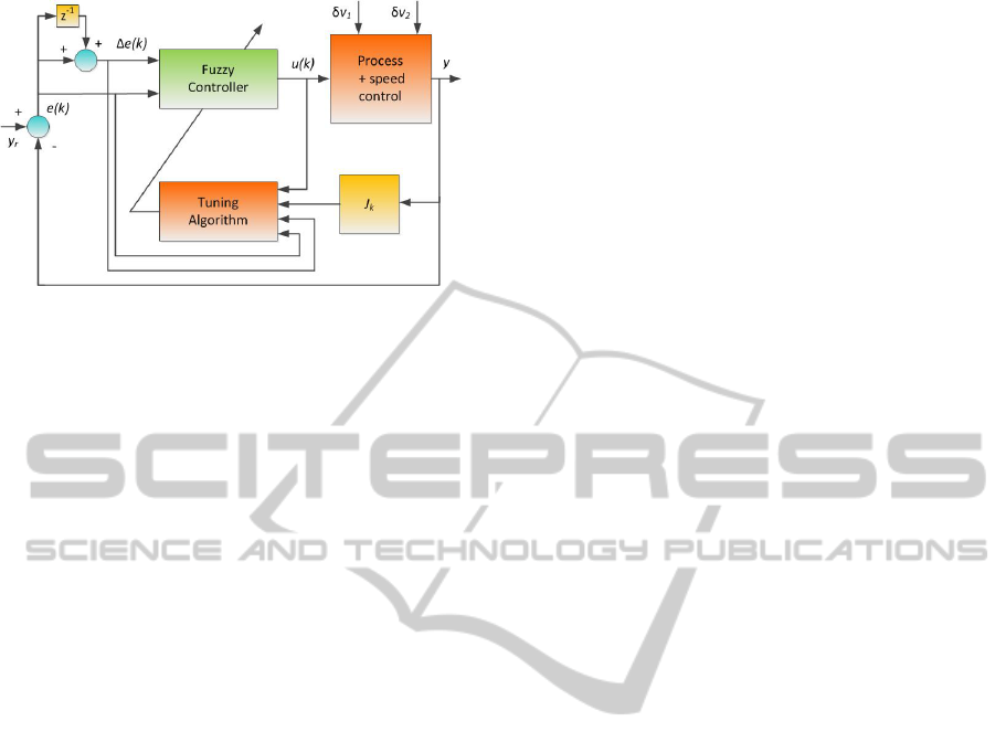
Figure 2: The structure of the lopper control system.
all measurements are given below.
4.1 Control Algorithms
In order to evaluate the proposed design flow, 3 con-
trol algorithms have been implemented. The classical
Proportional-Integral-Derivative (PID) algorithm, a
Fuzzy Logic Controller (FLC) algorithm used in the
lopper control of a rolling mill reported in (Janabi-
Sharifi and Fan, 2000) and the adaptive or Tuning
Fuzzy Logic Controller (TFLC) algorithm found in
the same publication. All implementations used sin-
gle precision floating point calculations natively sup-
ported by the latest versions of Vivado HLS and
linked to vendor supplied, optimized implementations
(Bagni and Mackay, 2013). So, the C code used for
hardware synthesis was the control algorithm trans-
lated from ST (i.e. 1 of the 3 algorithms). Algorith-
mic and architectural optimizations were applied, re-
sulting in deep optimization and design space explo-
ration.
The PID algorithm is a well known and widely
used digital control application. The FLC algorithm
found in (Janabi-Sharifi and Fan, 2000) is shown in
figure 2, including tuning (for no tuning, the Tuning
Algorithm block must be removed).
The main control parameters are the error signal
e(k), which is the difference between the required
process output y
r
and the measured y, and the error
change ∆e(k). These two signals comprise the state
vector x. The process input (or controller output) u(k),
u = [x1, x2]
T
or u = [e/Kin1,∆e/Kin2]
T
(Kin1 and
Kin2 are scaling factors), is based on a fuzzy logic
method and consists of three stages: fuzzification,
decision making and defuzzification. For fuzzifica-
tion, the linguistic variables for x1 take the values of
NB (Negative Big), NS (Negative Small), PS (Posi-
tive Small) or PB (Positive Big), while for x2 take the
values N (Negative), Z (Zero) or P (Positive), with
all membership functions being triangular and lim-
its [NBa,NBb], [NSa,NSb], [PSa,PSb], [PBa,PBb],
[Na,Nb], [Za,Zb] and [Pa,Pb] respectively. From this
scheme, grade membership values mNB, mNS, mPS,
mPB, mN, mZ and mP are calculated. For decision
making, a set of Mamdani heuristic fuzzy rules have
been selected, associating a real value w
i
with each
rule. Finally, defuzzification follows the pattern of the
Takagi-Sugeno controller, where u is the quotient of
the sum of grade memberships multiplied by rule w
i
values, over the sum of a set of production t-norms,
one for each Mamdani rule. When translated into C,
the FLC algorithm requires 26 floating point multi-
plications, 10 floating point divisions and 22 floating
point additions.
The final control algorithm, the TFLC, is gener-
ally a very complicated task. It is possible to tune
rules, operators and/or membership functions. In
(Janabi-Sharifi and Fan, 2000), membership function
tuning was performed using both back propagation
and descent methods. The TFLC algorithm when
translated to C, requires 106 floating point multiplica-
tions, 57 floating point divisions and 71 floating point
additions.
4.2 FPGA Implementations
A latest development in FPGA technology has been
Xilinx’s 7 series All Programmable FPGAs, built on
the state-of-the-art 28nm HPL process technology for
breakout performance, capacity, and system integra-
tion while optimizing price/performance/watt. For
evaluation reasons, different implementations of the
above 3 control algorithms, with these high perfor-
mance devices were taken, using a 100MHz clock
cycle and 4 of the latest evaluation boards, the Ar-
tix AC701 with the low end XC7A200T FPGA de-
vice, the Kintex KC705 with the medium range
XC7K325T FPGA device, the Virtex VC707 with
the high end XC7VX485T and the Zedboard with
the All Programmable System-on-Chip XC7Z020 de-
vice, which contains a dual core ARM microcon-
troller along with programmable logic. Without loss
of generality, the selection of Xilinx devices follows
the selection of Vivado HLS, which is a mature envi-
ronment with advanced integration capabilities with
other tools and methodologies.
Implementation details about the 3 algorithms are
given in tables 1, 2, 3 and 4. Each table corresponds
to a different evaluation board. For each algorithm
performance (latency and throughput in clock cycles,
for pipelined architectures) and area (Look-Up Ta-
ble function generators - LUTs, D-type Flip-Flops -
DFFs and special Digital Signal Processing blocks -
DSPs) measurements are given. Especially area mea-
surements are given both in absolute values as well as
ICINCO2014-11thInternationalConferenceonInformaticsinControl,AutomationandRobotics
730

Table 1: Implementation with the Artix-AC701.
Alg. Lat/cy Thr/put Area
LUTs DFFs DSPs
PID 27 5 526 790 5
(0%) (0%) (0%)
FLC 130 5 11599 8023 31
(8%) (2%) (4%)
TFLC 168 5 25804 24238 126
(20%) (9%) (17%)
percentages, with respect to the total number of avail-
able resources in each FPGA device.
As it can be seen in the previously mentioned ta-
bles, the simple PID algorithm can be easily imple-
mented in all evaluation boards with very small re-
source requirements (almost 0%) and a latency (ex-
ecution time for non pipelined architectures) of less
than 0.3 µsec, which can go as low as 0.04 µsec (the
throughput measurement) for pipelined architectures
(provided an appropriate FIFO input mechanism is
implemented). These numbers show the great poten-
tial of special purpose hardware accelerators for digi-
tal control.
The FLC algorithm also requires small amounts
of hardware, especially in the boards with more pro-
grammable logic resources (the AC701, the KC705
and the VC707). In the Zedboard, where the
XC7Z020 device consumes resources for the dual
core ARM microcontroller, almost 30% of the avail-
able LUTs are needed to implement the FLC algo-
rithm. Performance is again remarkable, with less
than 1.5 µsec latency and a 0.05 µsec or 0.04 µsec
throughput.
The most demanding of the implemented con-
trol algorithms, the TFLC almost fills Zedboard’s
XC7Z020 device, requires almost 20% of available
LUTs and DSPs and less than 10% of available DFFs
in AC701 and KC705 and requires less than 10% of
all resource types in the most advanced VC707. Ex-
ecution takes less than 2 µsec. This is a remarkable
figure considering that all calculations (exact numbers
for all algorithms have been given in the previous sub-
section) are single precision floating point, offering a
wide range of number representations and thus, nu-
meric stability.
Since in all experiments presented in tables 1-4 the
hardware resources needed to implement each con-
trol algorithm are substantially less than all available
resources, architectures with more than one controller
and other hardware modules are feasible, as discussed
in the following subsection.
Table 2: Implementation with the Kintex-KC705.
Alg. Lat/cy Thr/put Area
LUTs DFFs DSPs
PID 21 4 1422 1006 7
(0%) (0%) (0%)
FLC 100 4 17831 8600 41
(8%) (2%) (4%)
TFLC 134 4 45411 26007 151
(22%) (6%) (17%)
Table 3: Implementation with the Virtex-VC707.
Alg. Lat/cy Thr/put Area
LUTs DFFs DSPs
PID 21 4 853 1006 7
(0%) (0%) (0%)
FLC 100 4 13393 8588 41
(4%) (1%) (1%)
TFLC 134 4 31388 26105 151
(10%) (4%) (5%)
Table 4: Implementation with the Zynq Zedboard.
Alg. Lat/cy Thr/put Area
LUTs DFFs DSPs
PID 28 5 907 741 5
(1%) (0%) (2%)
FLC 149 5 14956 8775 31
(28%) (8%) (14%)
TFLC 189 5 38072 25771 126
(71%) (24%) (57%)
4.3 Multicore Architecture
Since all control algorithms implemented in FPGA
devices in the previous subsection leave empty space
for more functionality implemented in hardware, a
multicore architecture shown in figure 3 is proposed.
It consists of a general purpose microcontroller and a
number of special purpose hardware accelerators. All
general purpose work (i.e. user interface, communi-
cation with well known peripherals, etc.) is done by
the general purpose controller, while any application
specific functionality (i.e., PID, FLC or TFLC con-
trol) is done by the hardware accelerators. Each ac-
celerator is connected as a slave module in the mi-
crocontroller bus and can communicate with it with
bus transactions, either atomic or burst (for top per-
formance). The functionality of each accelerator may
differ from that of the others, provided it is required
by a specific application. The use of reconfigurable
FPGA devices and the corresponding HLS based de-
sign methodology presented above allows this change
in functionality with reduced design time overheads,
in order to cover more applications.
For Xilinx devices the general purpose microcon-
Program-basedandModel-basedPLCDesignEnvironmentforMulticoreFPGAArchitectures
731

Figure 3: The proposed multicore architecture.
troller can be either the ARM hardcore device found
in the Zynq family of chips or the Microblaze softcore
device that can be implemented in any device family.
For the Virtex family of devices and the VC707 eval-
uation board, which has been found to require less
than 10% of hardware resources for the 3 control al-
gorithms of the previous subsection, the Microblaze
is the best available choice. It has an advanced 32-bit
RISC Harvard architecture with options like an AXI
bus (ARM Ltd., 2013) interface, Memory Manage-
ment Unit (MMU), instruction and data side caches,
configurable pipeline depth and a Floating-Point Unit
(FPU). It is included free with Xilinx’s design tools
and evaluation boards.
Based on Microblaze and the architecture shown
in figure 3 a performance measuring experiment has
been conducted with the 3 control algorithms (PID,
FLC, TFLC) presented above. Specifically, each al-
gorithm was implemented in both software for the
Microblaze and hardware using HLS an the presented
methodology. For implementation, the Virtex VC707
evaluation board was selected. This time a 200MHz
clock for the board was used while the central clock
of the Microblaze microcontroller was chosen to be
150MHz. Also, Microblaze was equipped with 64KB
of local memory (from which all software was exe-
cuted, to avoid long communication delays with ex-
ternal DRAM) and an FPU for floating point calcu-
lations. Results are given in table 5, where execu-
tion times in nsec for 50 iterations of each control al-
gorithm in software (Microblaze code) and hardware
(the same C code passing through HLS) as well as
their differences are given.
Table 5 is the justification of the methodology pre-
Table 5: Hardware vs. software performance comparison.
Alg. Execution time (ns)
Hardware Software Gain
PID 129575 138855 9280
FLC 191175 1121482 930307
TFLC 1325442 4595868 3270426
sented in this paper. It shows that the same C code
(after translation from ST), can be used for either soft-
ware or hardware implementation with different per-
formance measurements. The hardware implementa-
tion is always faster. While the gain (difference be-
tween the two times) is small for the simple PID al-
gorithm, it is as high as almost 3.3 msec for the more
complicated TFLC. Since the code is the same, this
performance gain comes with improved productivity,
because no extra code conversion (manual or auto-
matic) has to be performed for either software or hard-
ware design (only the initial conversion from ST to
C, which is applied to both implementations). This
effect can be greatly enhanced with applications that
require more than one algorithm, if a hardware accel-
erator for each algorithm is generated, like the archi-
tecture of figure 3. Overall, the proposed methodol-
ogy offers advantages like fast prototyping, improved
performance and code reusability to digital control,
in an integrated manner, not found in other previous
approaches.
5 CONCLUSIONS
In this paper, a design environment and the corre-
sponding tool flow has been presented, that utilizes
ICINCO2014-11thInternationalConferenceonInformaticsinControl,AutomationandRobotics
732

program-based and model-based design, for the de-
velopment of PLC applications. Specifically, the pre-
sented tool flow supports either the design of new
control algorithms or the translation of existing al-
gorithms into C. Then, HLS and FPGA implemen-
tation tools are adopted, to implement the selected
algorithms as multicore, embedded designs, offering
performance improvements and hardware utilization
efficiency. Overall, the proposed methodology and
underlying tool flow support a novel high productiv-
ity prototyping platform for digital control applica-
tions, offering performance improvements compared
to software and very promising future extension capa-
bilities by utilizing state-of-the-art FPGA devices.
ACKNOWLEDGEMENTS
This research has been co-financed by the European
Union (European Social Fund - ESF) and Greek na-
tional funds through the operational program “Edu-
cation and Lifelong Learning” of the National Strate-
gic Reference Framework (NSRF) - Research Fund-
ing Program: ARCHIMEDES III: Investing in knowl-
edge society through the European Social Fund.
REFERENCES
Alonso, D., Suardiaz, J., Navarro, P. J., Alcover, P. M.,
and Lopez, J. A. (2009). Automatic generation of
VHDL code from traditional ladder diagrams apply-
ing a model-driven engineering approach. In 35nd
Annual Conference on Industrial Electronics, pages
2416–2421. IEEE.
ARM Ltd. (2013). AMBA AXI and ACE Protocol Specifica-
tion.
Bagni, D. and Mackay, D. (2013). Floating-point PID con-
troller design with Vivado HLS and system generator
for DSP. Xilinx Application Note XAPP1163.
Ben Othman, S., Ben Salem, A. K., Abdelkrim, H., and
Ben Saoud, S. (2012). MPSoC design approach of
FPGA-based controller for induction motor drive. In
International Conference on Industrial Technology,
pages 134–139. IEEE.
Ben Said, M.and Hemdani, A., Naouar, M. W., Monmas-
son, E., and Slama-Belkhodja, I. (2012). Standard
FPGA-based or full cSoC controllers for three-phase
PWM boost rectifier, two viable solutions. In 15th
International Power Electronics and Motion Control
Conference. IEEE.
Coussy, P. and Morawiec, A. (2008). High-level Synthesis:
From Algorithm to Digital Circuit. Springer-Verlag.
Economakos, C. and Economakos, G. (2008). FPGA imple-
mentation of plc programs using automated high-level
synthesis tools. In 17th International Symposium on
Industrial Electronics, pages 1908–1913. IEEE.
Ghosh, S., Barai, R. K., Bhattarcharya, S., Bhattacharyya,
P., Rudra, S., Dutta, A., and Pyne, R. (2013). An
FPGA based implementation of a flexible digital PID
controller for a motion control system. In Interna-
tional Conference on Computer Communication and
Informatics. IEEE.
Janabi-Sharifi, F. and Fan, J. (2000). A learning fuzzy sys-
tem for looper control in rolling mills. In International
Conference on Systems, Man, and Cybernetics, pages
3722–3727. IEEE.
Martin, G. and Smith, G. (2009). High-level synthesis: Past,
present, and future. IEEE Design and Test of Comput-
ers, 26(4):18–25.
Monmasson, E., Bahri, I., Idkhajine, L., Maalouf, A.,
and Naouar, W. M. (2012). Recent advancements
in FPGA-based controllers for AC drives applica-
tions. In 13th International Conference on Optimiza-
tion of Electrical and Electronic Equipment, pages 8–
15. IEEE.
Monmasson, E. and Cirstea, M. N. (2007). FPGA de-
sign methodology for industrial control systems - a
review. IEEE Transactions on Industrial Electronics,
54(4):1824–1842.
Monmasson, E., Idkhajine, L., Cirstea, M. N., Bahri, I., Ti-
san, A., and Naouar, M. W. (2011). FPGAs in in-
dustrial control applications. IEEE Transactions on
Industrial Informatics, 7(2):224–243.
Naouar, M. W., Monmasson, E., Naassani, A. A., and
Slama-Belkhodja, I. (2013). FPGA-based dynamic re-
configuration of sliding mode current controllers for
synchronous machines. IEEE Transactions on Indus-
trial Informatics, 9(3):1262–1271.
Navarro, D., Lucia, O., Barragan, L. A., Urriza, I., and
Jimenez, O. (2013). High-level synthesis for acceler-
ating the FPGA implementation of computationally-
demanding control algorithms for power convert-
ers. IEEE Transactions on Industrial Informatics,
9(3):1371–1379.
Patil, M. M., Subbaraman, S., and Nilkund, P. S. (2010).
IEC control specification to HDL synthesis: Consid-
erations for implementing PLC on FPGA and scope
for research. In International Conference on Control
Automation and Systems, pages 2170–2174. IEEE.
Silva, C. F., Quintans, C., Lago, J. M., and Mandado, E.
(2006). An integrated system for logic controller im-
plementation using FPGAs. In 32nd Annual Confer-
ence on Industrial Electronics, pages 195–200. IEEE.
Subbaraman, S., Patil, M. M., and Nilkund, P. S. (2010).
Novel integrated development environment for imple-
menting PLC on FPGA by converting ladder diagram
to synthesizable VHDL code. In 11th International
Conference on Control Automation Robotics and Vi-
sion, pages 1791–1795. IEEE.
Xilinx Inc. Vivado ESL design. http:// www.xilinx.com/
products/design-tools/vivado/integration/esl-design/
index.htm.
Program-basedandModel-basedPLCDesignEnvironmentforMulticoreFPGAArchitectures
733
