
Hybrid Control Architecture for Mobile Robots Navigation in
Partially Known Environments
Madjid Hank
1
and Moussa Haddad
2
1
Laboratoire Systèmes Numériques, Ecole Militaire Polytechnique, BP 17 Bordj El Bahri, 16111 Algiers, Algeria
2
Laboratoire Mécanique des Structures, Ecole Militaire Polytechnique, BP 17 Bordj El Bahri, 16111 Algiers, Algeria
Keywords: Autonomous Mobile Robots, Navigation, Trajectory Tracking and Planning, RPA, Fuzzy Logic.
Abstract: In this paper, we are interested on the development of hybrid control architecture for autonomous mobile
robots navigation. The proposed approach consists of an architecture adapted for partially known
environments. It includes both reactive navigation methods based on the principle of Sense & Act and
deliberative methods based on the principle of Sense-Plan & Act. The used reactive navigation method is a
behavioural approach for navigation in unknown environments. Whereas deliberative approach is based on
a polynomial method called Random-Profile-Approach (RPA) for optimal trajectory planning in known
environments. Controllers used for both trajectories tracking and reactive navigation are fuzzy inference
systems. Simulation and experimental results to validate the proposed navigation strategy are presented.
1 INTRODUCTION
The aim of this work is to define a hybrid control
architecture for autonomous mobile robots
navigation in partially known environments. This
thematic presents a promising research line given the
diversity of its applications: military applications
(combat robots, tactical vehicles, intelligent robot
used in surveillance and reconnaissance...), civil
protection (neutralization of terrorist activity,
demining ...), industrial applications (monitoring of
vulnerable sites, performing of repetitive tasks,
manipulating of radioactive materials in nuclear sites
...) and space applications (planetary exploration ...).
In most of these applications, the performing of a
task by a mobile robot requires:
The maximum exploitation of the available
information’s on the environment. Generally, in a
mobile robot navigation problem, we can always
get a minimum of information on the navigation
environment. Therefore, this assumption
characterizes the navigation environments as
partially known environments both in indoor or
outdoor navigation. This can be generally verified
in many applications: For indoor navigation, as in
industrial application, some information may be
available on accesses and corridors of the
workshop. In outdoor navigation, as in the transport
sector, we can have some information on the roads
map, intersections and roundabouts.
The maximum exploitation of the available
geometric, kinematic, and dynamic system
performances to minimize the execution time of the
task. In fact, to determine an optimal trajectory for
the robot, we must take into account the physical
limits of actuators (velocity, acceleration, torque).
The exploitation of perceptual and decisional
capacities available on the system. Indeed, during
the performing of a task, the robot must use its
perception capacities and must be provided by
decisional capacities for avoidance of static and / or
dynamics obstacles.
In such situations, control architectures based
only on trajectory planning or reactive navigation
methods have limitations. For example, in the case
of deliberative control architectures (based on
trajectory planning), avoidance of unexpected and
dynamic obstacles is not taken into account.
Furthermore, in the case of reactive control
architectures, the execution time of the task can be
very long, with the risk of lock in local minimum in
some situations. Hence the necessities of developing
a hybrid control architecture by combining methods
of trajectory planning with reactive navigation
approaches. The choice of a hybrid approach of
navigation is motivated by the assumption that
considers environments as partially known.
513
Hank M. and Haddad M..
Hybrid Control Architecture for Mobile Robots Navigation in Partially Known Environments.
DOI: 10.5220/0005067305130521
In Proceedings of the 11th International Conference on Informatics in Control, Automation and Robotics (ICINCO-2014), pages 513-521
ISBN: 978-989-758-040-6
Copyright
c
2014 SCITEPRESS (Science and Technology Publications, Lda.)

In this article we are interested in the development
of a hybrid control architecture. The adopted
navigation strategy consists in planning, and
tracking a reference trajectory to move the robot
from an initial configuration to another
configuration. This allows access to an action area
considered as an unknown environment (UAA).
Once in the UAA, the robot calculates a solution to
reach the desired goal, using a reactive navigation
method. The reference trajectory planning is based
on the Random-Profiles-Approach (RPA) (Haddad,
2007) while their tracking and reactive navigation
phases are realized using fuzzy logic controllers
(Souici, 2007), (Nemra, 2008).
2 RELATED WORK
Navigation problem for autonomous mobile robots
consists to look for a trajectory to move from an
initial point to a desired goal while avoiding
obstacles (Haddad, 2007), (Guechi, 2010). However,
to perform a navigation task, the robot must have
perceptual, decisional and actions capacities in order
to interact with the environment. The sequence of
the cycle Perception-Decision-Action (P-D-A) is
managed by the control architecture (navigation
system), which generally consists of three levels
(Lee-Johnson, 2007): deliberative level (decision
making and planning), reactive level (trajectory
tracking, velocity and direction control) and
hardware level (actuators and motors control).
The type and complexity of control architecture
are usually related to the complexity of the
environment and the considered task (Durand,
2012). Navigation methods are classified into two
main categories (Chen 2010): methods with
reference a priori planned trajectory (deliberative
navigation or global planning methods) and
approaches without explicit trajectories (called
reactive navigation or even local planning methods).
Reactive navigation methods do not require a
priori knowledge on the environment model and
sometimes without the explicit model of the robot.
In the literature several methods are developed: The
most used are those based on artificial potential
field, fuzzy logic and artificial neural networks
(Morette, 2009). These methods are generally
applied to unknown environments and can be easily
adapted to the dynamically changing environments.
However, such methods suffer from the problems of
local minima (non convergence to a feasible
solution) (Guechi, 2010). In addition, the robot
travelled trajectory is not optimal in terms of
distance and / or travel-time, due to lack of a global
vision on the environment.
However, in deliberative navigation approaches,
a navigation task can be achieved in two steps:
trajectory planning and tracking phases. Planning a
trajectory for the robot is conditioned by the
satisfaction of a performance criterion (distance,
travel-time, energy consumption ...) and the respect
of a certain number of constraints (geometric,
kinematic and/or dynamic) (Haddad, 2007). This
ensures a safe and fast solution navigation respecting
kinematic and dynamic capacities of the robot, and
the constraints related to the environment. However,
these methods do not adapt to the dynamic of the
environment (unexpected obstacles) or completely
unknown environment (Guechi, 2010).
As regards to the trajectory planning, several
approaches are proposed in the literature, in which
the trajectory is generally made up of line segments
connected via tangential circular arcs. Most of these
works deal with minimum-time trajectory-planning
problems, solved via PMP, under linear/angular
velocity bounds of the platform. Some performance
techniques have been developed to reach the goal as
quickly as possible by smoothing transitions, thus
achieving continuous-curvature trajectories.
(Haddad, 2010), (Balkcom, Aydin, 2002),
(Labakhua, 2006), (Hentschel, 2007), (Qin, 2000).
Concerning the problem of trajectory tracking, it
consists to follow a reference trajectory by
minimizing the position, orientation and sometimes
speeds errors while maintaining the robot stability.
Many control methods are proposed, we mention
here some of the most used: the classic PID control,
Lyapunov-based nonlinear controllers (Blažič,
2011), sliding mode control (Levant, 1993),
(Hamerlain, 2005), (Lucet, 2009) and fuzzy logic
(Lee, 2003), (Nejat, 2011), which is recently
introduced in a new form called PDC control
(Parallel Distributed Compensation) presented by
(Guechi, 2010), it consists of rewriting the kinematic
error model of the mobile robot tracking problem
into a TS fuzzy representation.
According to the available information on the
navigation environment, methods of the first or
second group are selected. This leads for three
classes of control architectures: reactive, deliberative
and hybrid ones (Lee-Johnson, 2007) (Durand,
2012). Reactive control architectures are based on
the “Sense & Act” principle that combines trajectory
planning and its execution in a same level.
Generally, they are composed from a set of specific
behavioural modules (task-specific behaviours). This
allows the robot to take real-time decisions based on
ICINCO2014-11thInternationalConferenceonInformaticsinControl,AutomationandRobotics
514

local perception and reactive interactions required in
unknown and dynamically changing environments.
The reference of the majority proposed solutions is
the Subsumption architecture proposed by Brooks. It
can be divided into two main classes based on
competitive or cooperative mechanisms between
behaviours modules (Ye, 2001), (Silas, 2011),
(Adouane, 2009), (Simpson, 2006).
Deliberative control architecture based on
“Sense-Plan-& Act” principle used in fully known
environments. In fact, the robot model must be
known and continually updated to plan the robot
actions. Therefore, one or more trajectories are
planned. Then, according to the actual state of the
perceived information the robot executes these
trajectories. Deliberative systems are considered as
classical control architectures, since they were the
first to be tested. We note here the distributed
CODGER and the NASREM architectures which
present multilayer hierarchical levels of processing
(Silas, 2011).Given the drawbacks of the two types
of methods, the combination of both types gives
hybrid control architectures to enable navigation in
partially known environments. This choice allows
fast and reactive solution while avoiding unexpected
obstacles, and reducing the travelling time with
introduction of partial knowledge on the
environment. In (Lee-Johnson, 2007) a multi-layered
architecture is employed, it incorporates reactive
control, deliberative path planning and exploration
capabilities.
In (Tian, 2010) a navigation control strategy for
rescue robot is designed by the tight integration of
both reflecting and reactive behaviours with
deliberative module. In (Vuković, 2009) the
proposed architecture is founded on the use of
Artificial Neural Networks for assemblage of fast
reacting behaviours, obstacle detection and module
for action selection based on environment
classification. Garcia and al. (Garcia, 2007) propose
deliberative/reactive control architecture of a
scanning manipulator for detecting antipersonnel
landmines. The deliberative controller defines a
sweep trajectory that furnishes complete coverage of
the search area, while two reactive controllers are
involved in on-line adaptation to the environment.
3 KINEMATIC OF THE ROBOT
The used platform in this work is the Pioneer P3-AT
mobile robot produced by ActivMedia which is
mostly used for scientific, and research experiments.
Different sensors are attached or embedded to it:
sonar sensors, laser telemeter, camera, odometer
sensors…etc. The P3-AT is a four-wheel skid-
steering mobile robot (SSMR) with a maximum of
translation and rotation velocities fixed at 600 mm/s
and 140 °/s respectively. Instantaneous linear and
angular velocities are determined due to difference
between the left and the right speed of the wheels v
l
and v
r
(equ.4, Figure 1), (Silas, 2011).
Figure 1: Kinematics of the Pioneer P3-AT mobile robot.
Let
,
,
,
to be the global
referential system linked to the environment and
,
,
,
the mobile referential
system linked to the robot. The situation of the
referential system R
m
relatively to R
g
is defined by
three parameters: two translations parameters (x and
y) and a rotation parameter θ around the vertical
axis. The rotation matrix from R
m
to R
g
is given by :
cosθsinθ0
sinθ cosθ0
001
(1)
The vector of the generalized coordinates system
is defined by the vector
T
. The direct
kinematic model of the robot can be expressed by
the following relationship:
cosθt 0
sinθt 0
01
(2)
With v and w are respectively the linear and
angular velocities of the robot, expressed as a
function of the wheel speeds as follows:
0.5 0.5
1
⁄
1
⁄
(3)
The non-holonomic constraint is given by :
0
(4)
x
0
L
Y
g
v
l
x
m
y
m
L
V
W
v
r
X
g
y
0
HybridControlArchitectureforMobileRobotsNavigationinPartiallyKnownEnvironments
515
4 PROBLEM FROMULATION
4.1 Trajectory Planning and Tracking
In a trajectory planning problem (Chen, 2010), the
robot should move freely from an initial
configuration
,
,
to a final one
,
,
.We must determine the trajectory
q(t), the travelling time T of this trajectory and the
actions (t) (speed or torque) applied to the robot’s
actuators, such as the initial and final states are
matched, all constraints are respected and a given
performance index J is optimized. In addition to
non-holonomic constraint (equ.4), the set of feasible
motions are restricted by numerous constraints that
must be satisfied during the travel from q
i
to q
f
.
These constraints concern boundary conditions of
the considered task, non-collision between the robot
and obstacles, and physical limitations on the robot
kinematic performances:
Boundary conditions
qt0q
etqtTq
(5a)
q
t0
0etqtT0
(5b)
Obstacles avoidance
Collision (q) = false (6)
The Boolean function Collision indicates
whether the robot at configuration q is in collision
with obstacles presents in the workspace.
Physical limitations
Velocities and Accelerations:
|
|
,
|
|
(7a)
|
|
,
|
|
(7b)
The goal function J to be minimized, represents
the travel cost between initial and final states T,
calculated as follow:
J = T (8)
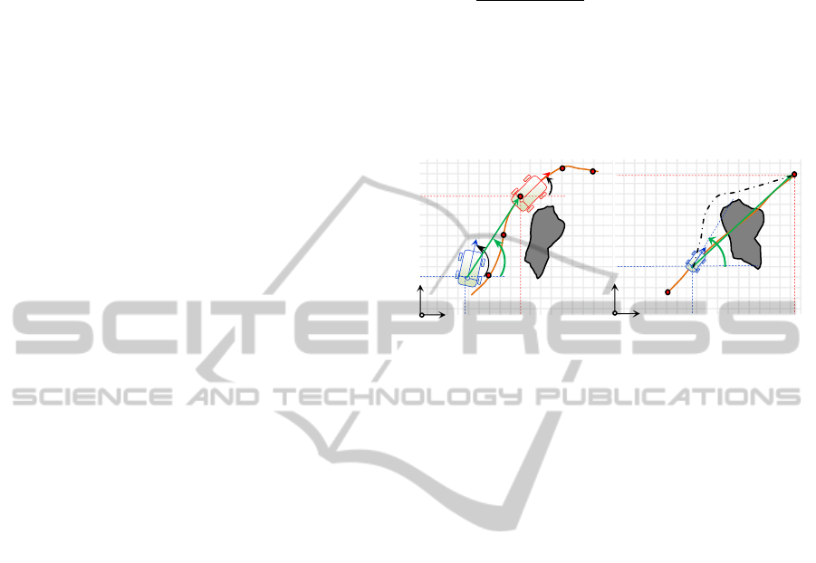
The trajectory tracking module used in this paper
is based on a so called virtual vehicle approach
(Simpson, 2006). The principle of this approach,
illustrated by the scheme of the figure (2a), is to
minimize the position and orientation errors between
the real and the virtual vehicle, in order to follow the
virtual vehicle considered as a moving target. The
virtual robot goal changes its coordinates at each
time step according to the reference trajectory. In
fact, we define the position and orientation errors e
p
and e
θ
by:
∆
∆
,
2∆,∆
(9)
Where
∆
,∆
and
,
,
are coordinates of the virtual vehicle (fixed by the
reference trajectory) and ,,
are generalized
coordinates measured by the localization system
(odometer in our case).
Figure 2: (a) Trajectory tracking problem based on virtual
approach, (b) reactive navigation problem in unknown
environment.
4.2 Reactive Navigation Problem
Concerning reactive navigation problem, we are
interested on a real time determination of the robot
trajectory in unknown environment. The objective is
to reach a desired goal from an initial configuration
while avoiding encountered obstacles. The used
navigation approaches in this case are based on the
principle of Sense & Act, where the robot must
calculate actions to apply in the current situation
based on sensors information.
Since the navigation areas are considered as
unknown environment, the robot must have multi-
objectives. First, it should seek the desired goal
while minimizing the angular and position errors,
respectively e
θ
and e
p
, between the robot and goal
coordinates, calculated by the same expression of
equations (9a) and (9b) expect thatx
,y
given by
the reference trajectory are replaced by the goal
coordinatesx
,y
. Second, the robot should avoid
any encountered obstacles, where it must calculate a
new trajectory by changing its initial orientation
(Figure 2b).
5 THE PROPOSED APPROACH
The proposed approach in this paper is an
appropriate navigation strategy for partially-known-
environments. The robot is located at a well-defined
x
y
x
r
y
r
Obstacle
Actual
configuration
Planned
Trajectory
x
y
x
g
y
g
Obstacle
e
p
e
Actual
configuratio
Virtual robot
Desired Goal
(
b
)
(
a
)
ICINCO2014-11thInternationalConferenceonInformaticsinControl,AutomationandRobotics
516
initial configuration in the global reference; the aim
of the proposed approach is to define a hybrid
control architecture combining RPA with a reactive
navigation method based on fuzzy logic. This
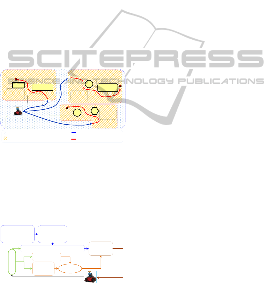
strategy consists of three steps (Figure 3):
i) The first is a preliminary step that consists to
divide the environment into several unknown
action areas (UAA). For each UAA, we generate
optimal trajectories using RPA between the
initial configuration of the robot and access
configurations of different UAAs;
ii) Second, an UAA is selected according to a
demand. Thereafter, the robot follows the
defined trajectory until the access configurations
of the selected UAA using a fuzzy controller;
iii) Finally, once there, the robot calculates a
solution using a reactive navigation approach
based on fuzzy logic in order to reach the final
desired goal in the selected UAA.
Figure 3: Descriptive diagram of the navigation approach.
The proposed navigation strategy is described by
the scheme of Figure (4) that consists of trajectory
planning module using RPA and a fuzzy logic based
trajectory tracking module for the deliberative part.
The reactive part is composed of two behavioural
modules for obstacles avoidance and goal seeking
based on fuzzy logic systems too. A transition
module allows the robot to switch between the two
navigation types.
Figure 4: Proposed control architecture.
5.1 Optimal Trajectory Planning using
RPA
The used approach (RPA) was developed by
(Haddad, 2007). It is based on three fundamental
aspects: the normalization of the time-scale, the
decomposition of the trajectory to a path and
movements on this path, and modelling the path and
movements by parametric functions.
Using the normalization of the time-scale,
εε withε1/T, a trajectory q(t)
can be uniquely characterized by a travel time T and
a trajectory profile Q(ε). The purpose of this
normalization is that for any trajectory class Q, we
can apply a windowing process which not only
enables to easily find the best score J
Q
accessible in
this class but also allows finding the time specific
movement T
Q
which distinguishes its best candidate.
Thus, the difficult task of finding the optimal
trajectory q(t)
best
with the unknown travelling time
T
best
can be reduced to find the profile Q(ε)
best
of this
optimal trajectory. With this decomposition
path/movement, every trajectory profile Q(ε) is
defined by two parametric functions, ε
λλε, the first
λ
with λ∈
0,1
describes
the geometric path of the robot while the other, λε
defines the way in which this path will be travelled.
This decomposition provides the ability to:
Choose an approximation adequate model for each
function that allows to take into account a part of
the boundary conditions;
Reject early candidate if the corresponding path
violates any geometric constraints, which results in
a reduction of the overall computation time,
Take into account non-holonomic constraints when
generating the path of the mobile robot.
Finally, by means of a discretization of the two
functions, path and movement, the path planning
problem, which is naturally an optimal control
problem is converted to a parametric optimization
one. In this discretization, each candidate profile
path is defined as a finite set of free control points.
As a result, the trajectory planning problem is
converted to finding the optimal position, of a few
control points randomly perturbed by a suitable
model (Haddad, 2007).
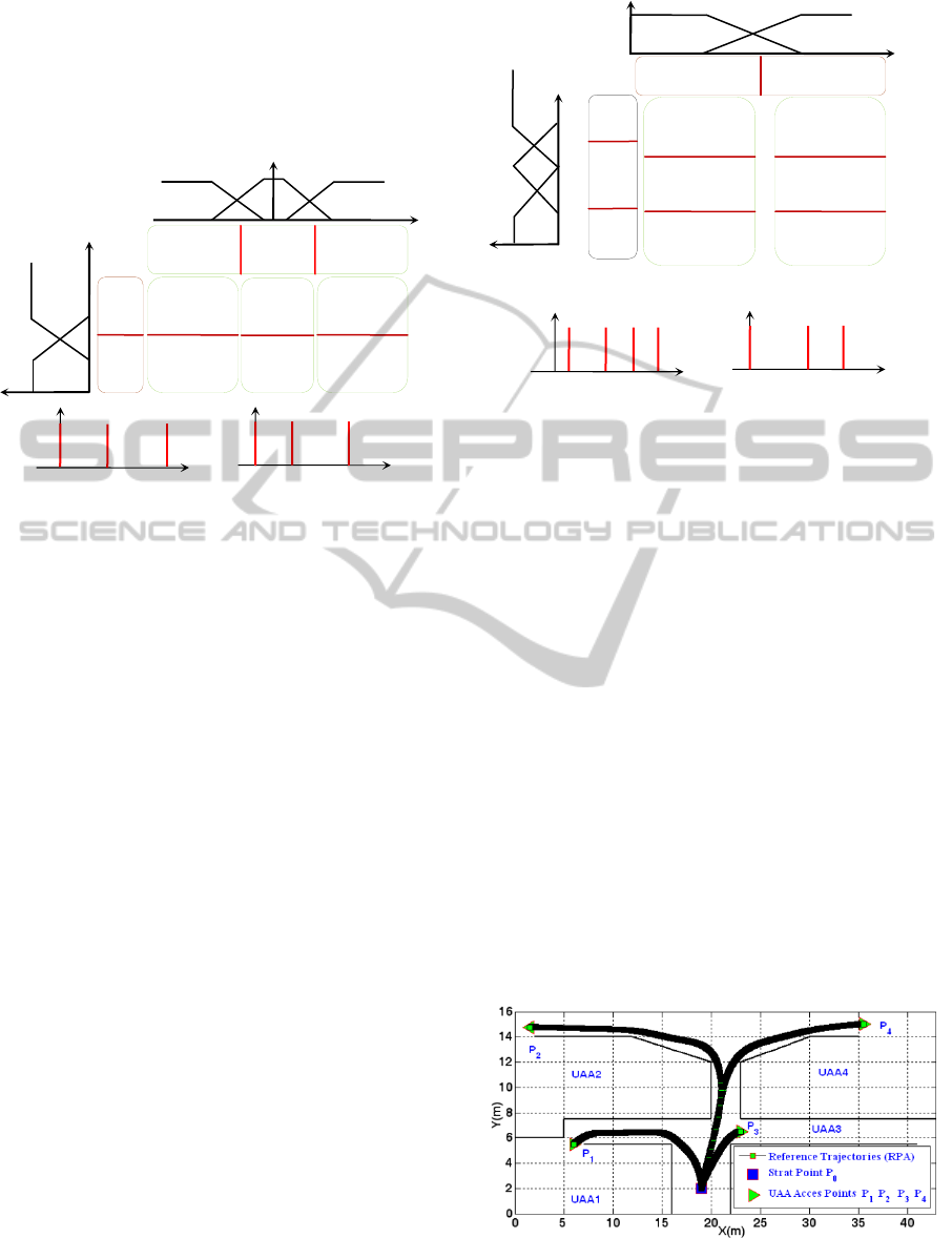
5.2 Trajectory Tracking and Goal
Seeker Modules
The trajectory tracking module is the same one for
goal seeking. Based on fuzzy logic control, the
system inputs are the position and orientation errors
e
p
and e
θ
given by equations (9a) and (9b). The
Trajectory tracking controller
Prior
knowledge on
the environment
Perce
p
tio
RPA
Trajectory
p
lannin
g
Transitio
n module
Fusion
Goal Seeker
Obstacle
Avoider
Obstacle
Obstacl
Goal
(
x
g
,
y
g
)
Initial
location
Known parts of the environment Trajectories tracking
Unknown action areas (UAA) Reactive navigation
Area N°
01
Area
N
°
02
Area
N
°
03
Goal
(
x
g
,
y
g
)
Goal
(
x
g
,
y
g
)
UAA
Access
HybridControlArchitectureforMobileRobotsNavigationinPartiallyKnownEnvironments
517
outputs of the selected Takagi-Sugeno controller are
linear and angular velocities of the robot v and w
respectively. This choice allows the determination of
output commands by a simple relationship from the
rules conclusions. The fuzzy rules basis and
input/output sets are illustrated in the Figure (5).
Figure 5: Fuzzy rules basis and outputs sets for the
trajectory tracking and goal seeker controller.
5.3 Obstacles Avoidance Module
The principle of obstacle avoidance control is based
on a wall following behaviour. The used fuzzy
controller has two inputs: frontal and side (minimum
of left and right) distances from obstacles, measured
in the three directions by a laser telemeter embedded
on the P3-AT mobile robot. The robot must follow
the wall of the nearest obstacle at the left and right
directions while keeping the frontal distance as the
greatest as possible. The fuzzy rules basis and
input/output fuzzy sets are defined in the Figure (6)
in the case of left wall following, the right one is
obtained by putting w
r
= -w
l
. We note here that
positions of fuzzy conclusions of both goal seeking
and obstacles avoidance are optimized using
reinforcement learning (fuzzy Q-learning) as in
(Souici, 2007) and (Nemra, 2008).
6 SIMULATIONS RESULTS
In order to test the proposed approach, we use the
MobileSim simulator to represent the robot and its
environment. Obstacles are represented in a 2D
model map using Mapper3 software. To interface
with MobileSim we use ARIA C++ library which
provides an interface and framework for controlling
and receiving data from the P3-AT mobile robot
platform. ARIA enables to read sensor’s data and
Figure 6: Fuzzy rules basis and outputs sets for the
obstacles avoidance controller.
send commands to the actuators both in simulations
or real applications.
The proposed strategy techniques are applied to
the case of the environment presented on the Figure
(8) with four unknown action areas (UAAs). The
robot is considered at an initial configuration P
0
. For
each action area, the access configuration points P
1
,
P
2
, P
3
and P
4
are defined. In each UAA a goal is
defined by its configuration
,
,
: G
1
, G
2
, G
3
and G
4
. The Figure (7) shows the four trajectories
between the initial configuration of the robot P
0
and
UAAs access P
1
... P
4
, determined using RPA.
In Figure 8 we present the performance of tasks
taking the robot at each goal G
i i = 1 … 4
in a desired
UAA from its initial configuration P
0
. First, the
robot passes through defined access points P
i i = 1 … 4
for each UAA while following reference trajectories
given by RPA. Once arriving, the robot switches to
reactive navigation techniques, to search a trajectory
in order to reach the desired goal while avoiding
encountered obstacles.
Figure 7: Reference trajectories determined using RPA.
w
(
°/s
)
µ
w
v (mm/s)
µ
v
80 400 500 600 0 20 30
Z
w
A
w
G
w
Z
v
S
v
A
v
G
v
mm)
Small Big
1
500
1
900
µ
mm)
v is A
v
w is Z
w
v is G
v
w is A
w
v is G
v
w is Z
w
v is
S
v
w is -G
w
v is S
v
w is Z
w
v is Z
v
w is -G
w
700 1200 1500
Small Average Big
µ
w (°/s)
v
(
mm/s
)
µ
v
0 150 600
0 5 30
Z
w
S
w
G
w
Z
v
S
v
G
v
v is
G
v
w is -G
w
v is S
v
w is -
S
w
v is
G
v
w is Z
w
v is Z
v
w is Z
w
v is
G
v
w is G
w
v is S
v
w is
S
w
50 600
Small
Big
-10 -2 +2 +10
Negative Zero Positive
µ
µ
°
mm)
ICINCO2014-11thInternationalConferenceonInformaticsinControl,AutomationandRobotics
518
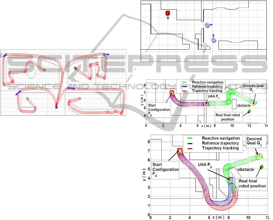
The four selected areas are different cases for testing
the navigation strategy: The first is a simple example
of wall tracking. In the second, the robot must avoid
encountered obstacles on its trajectory to reach the
goal, while in the third the robot must pass through a
corridor to reach the goal point. Finally, the fourth
UAA presents a case of a maze in a zigzag form. For
each selected area, the robot executes the defined
trajectories and reaches the goal while avoiding
encountered obstacles, exploiting kinematics
performance (speeds) and respecting its physical
limits. The adopted solution has proved its
effectiveness through testing simulations presented
in Figure 8. Trajectory tracking is performed
correctly in the allotted time with an acceptable
errors remaining.
Figure 8: Simulations results obtained from tests of the
hybrid architecture.
7 EXPERIMENTAL RESULTS
In order to validate the proposed approach on a real
robot, we choose the environment illustrated by the
figure (9) that represents a part of the EMP Robotic
Laboratory with dimensions of 8.75m by 14m. The
robot is considered at an initial configuration P0:
(3m, 7m, -90°). Two point access are considered for
the UAA and given by the centre coordinates of the
two UAA doors
8,5.5,0° and
8.2,3.5,0°.
For each goal a reference trajectory is defined using
RPA. The Figure (10) shows the planned trajectories
(blue) between the initial configuration of the robot
P
0
and two goals P
1
and P
2
.
The obtained experimental results are acceptable
for the two presented cases. However, the choice of
a reduced environment comparatively to the used
one in simulation results is justified by the
degradation of the positioning precision because of
introduced error by the used odometer. In fact, for
trajectory tracking phase in the first case the error is
acceptable because the trajectory does not present
severe manoeuvres. But in the second case the error
is greater because of the two curves presenting a
change of orientation and causing a skid of the robot
which is the main source of odometer errors. In the
phase of the reactive navigation, errors take an even
greater value because of manoeuvres made by the
robot in order to avoid encountered obstacles. So,
we mention an error that exceeds 1 meter between
the real robot final position and the given one by the
odometer.
Figure 9: Used environment for experiments on real robot.
Figure 10: Experimental results.
8 CONCLUSIONS
We have proposed a hybrid approach for mobile
robot navigation in partially known environments,
based in combining of trajectory tracking module
with reactive navigation behaviours we have tested
the defined global navigation strategy using fuzzy
logic in virtual environment in order to validate it.
Real time applications with the P3-AT mobile robot
P
1
P
2
P
0
P
0
P
3
P
4
P
1
P
2
G
2
G
1
G
4
G
3
HybridControlArchitectureforMobileRobotsNavigationinPartiallyKnownEnvironments
519

are presented in real environment. Obtained results
in both simulations and real time applications are
acceptable. Future work will focus on the
improvement the navigation strategy using more
intelligence in transition phase, and the use of more
accurate localization system.
REFERENCES
Haddad, M., Chettibi, T., HANCHI, S. LEHTIHET, H.E
A random-profile approach for trajectory planning of
wheeled mobile robots. European journal of
Mechanics-A/Solids, Vol.26 (3), 2007, pp 519–540.
Souici, A., Rezine, H., Learning Goal Seeking and
Obstacle Avoidance using the FQL Algorithm, in
Proc. World Cong. on Engineering and Computer
Science, 2007, San Francisco, USA.
Nemra, A., Rezine, H., Genetic Reinforcement Learning
Algorithms for On-line Fuzzy Inference System
Tuning, Application to Mobile Robotic. Robotics
Automation and Control, Pavla Pecherkova, Miroslav
Flidr and Jindrich Dunik (Ed.), ISBN: 978-953-7619-
18-3, 2008, InTech.
Guechi, E., Lauber, J., Dambrine, M., Klančar G., Blažič,
S., PDC control design for non-holonomic wheeled
mobile robots with delayed outputs. J. Intell. Robotics
Syst. 60(3-4), 395–414, 2010.
Lee-Johnson, C., Carnegie, D., Applications of an
Adaptive Hierarchical Mobile Robot Navigation
System. In Proc. of the Australasian Conf. on Robotics
and Automation, 2007, Australia.
Durand, B., Proposition d’une architecture de contrôle
adaptative pour la tolérance aux fautes. Ph.D.
dissertation, Montpelier II Univ., France, 2012.
Chen, C., GREY, D., System Based Reactive Navigation
Of Mobile Robots Using Reinforcement Learning.
International Journal of Innovative Computing,
Information and Control, Volume 6, Number 2,
February 2010.
Morette, N., Contribution à la Navigation de robots
mobiles : approche par modèle direct et commande
prédictive. Ph.D. dissertation, Orléans Univ., France,
2009.
Haddad, M. Khalil, W. and Lehtihet, H. E., Trajectory
Planning of Unicycle Mobile Robots with a
Trapezoidal-Velocity Constraint. IEEE Transactions
on Robotics,DOI:10.1109/TRO (2010), 2062090.
Balkcom, D., MASON, M., Extremal trajectories for
bounded velocity mobile robots t. Proc. of IEEE Int.
Conf. on Robotics & Automation, 2002.
Labakhua, L., NUNES, U., RODRIGUIES, Smooth
Trajectory Planning for Fully Automated Passenger
Vehicles-Spline and Clothoid based Methods and its
Simulation. In Proc. of the Int. Conf. on Informatics in
Control, Automation and Robotics (ICINCO), pp. 89-
96. 2006.
Hentschel, M., and al., Deterministic path planning and
navigation for an autonomous fork lift truck. 6th IFAC
Symposium on Intelligent Autonomous Vehicles (IAV
2007).
Qin, B., Soh Y. C., Xie M., and Wang D., Optimal
trajectory generation for wheeled mobile robot”. In
Proc. Of 5th International Conference on Computer
Integrated Manufacturing, pp. 434-444. 2000.
Aydin S., Temeltas, H., a novel approach to smooth
trajectory planning of a mobile robot. IEEE Int
Workshop on Advanced Motion Control, pp 472-477,
2002.
Blažič, S., A novel trajectory-tracking control law for
wheeled mobile robots. Robotics and Autonomous
Systems 59, 2011, 1001-1007.
Levant, A., Sliding order and sliding accuracy in sliding
mode control, International Journal of Control,
6(58):1247_1263, 1993.
Hamerlain, F., Achour, K., Floquet, T., Perruquetti, W.
Higher order sliding mode control of wheeled mobile
robots in the presence of sliding effects. In 44 th IEEE
Conf. on Decision and Control, ECC’05, Séville,
2005.
Lucet, E., Grand, C., Sallé, D., and Bidaud, P. , Dynamic
control of the 6WD skid-steering mobile robot
RobuROC6 using sliding mode technique. ICRA 2009.
Lee, T., Lam, H., Leung, F., and Tam, P., a practical fuzzy
logic controller for the path tracking of wheeled
mobile robots. IEEE Control Systems Magazine. April
2003.
Nejat, H., Pishkenari, A., Mahboobib, S., Alasty, A.,
Optimum synthesis of fuzzy logic controller for
trajectory tracking by differential evolution. Scientia
Iranica B (2011) 18 (2), 261–267.
Ye, C., Wang, D., Novel behaviour fusion method for the
navigation of mobile robots. Proceedings of the IEEE
International Conference on Systems, Man, and
Cybernetics, Nashville, TN, 2001, pp. 3526-3531.
Silas, F. Alves, R., Joao, M. & al, (2011), Conceptual
Bases of Robot Navigation Modeling, Control and
Applications, Advances in Robot Navigation, Prof.
Alejandra Barrera (Ed), ISBN: 978-953-307-346-0,
InTech.
Adouane, L., Hybrid and Safe Control Architecture for
Mobile Robot Navigation, 9th Conference on
Autonomous Robot Systems and Competitions –
Robotica’09, Castelo Branco, Portugal, 2009.
Simpson, J., Jacobsen, C., and Jadud, M., Mobile Robot
Control The Subsumption Architecture and occam-pi,
Communicating Process Architectures, IOS Press,
2006.
Tian, F., Ge, S., Zhu, H., A Navigation control strategy
with hybrid architecture for rescue robot, Proc. of
IEEE Int. Conf. on Intelligent Computing and
Intelligent Systems (ICIS10) Xiamen, China, 2010 ,
pp: 675 – 680 volume 1.
Vuković, N., Miljković, Z., New Hybrid Control
Architecture for Intelligent Mobile Robot Navigation
in a Manufacturing Environment, FME Transactions,
2009, 37, 9-18.
Garcia, E., Gonzalez, P., Hybrid deliberative/reactive
control of a scanning system for landmine detection,
ICINCO2014-11thInternationalConferenceonInformaticsinControl,AutomationandRobotics
520

Robotics and Autonomous Systems, Vol. 55, pp. 490-
497, 2007.
Precup, R.-E., Tomescu, M. L., Radac, M.-B., Petriu, E.
M., Preitl, St. and Dragos, C.-A. (2012): Iterative
performance improvement of fuzzy control systems
for three tank systems. Expert Systems with
Applications (Elsevier Science), vol. 39, no. 9, pp.
8288-8299.
Hsu, C.-H. and Juang, C.-F, Multi-objective
continuousant-colony-optimized FC for robot wall-
following control, IEEE Computational Intelligence
Magazine, vol. 8, no. 3, pp. 28-40, 2013.
HybridControlArchitectureforMobileRobotsNavigationinPartiallyKnownEnvironments
521
