
Computationally Efficient Multi-Objective Optimization of and
Experimental Validation of Yagi-Uda Antenna
Adrian Bekasiewicz
1
, Slawomir Koziel
2
and Leifur Leifsson
2
1
Faculty of Electronics, Telecommunications and Informatics, Gdansk University of Technology, 80-233 Gdansk, Poland
2
Engineering Optimization & Modeling Center, Reykjavik University, Menntavegur 1, 101 Reykjavik, Iceland
Keywords: Antenna Design, Design Optimization, Multi-Objective Optimization, Electromagnetic Simulation,
Simulation-Driven Design, Design Space Reduction, Surrogate-based Optimization.
Abstract: In this paper, computationally efficient multi-objective optimization of antenna structures is discussed. As a
design case, we consider a multi-parameter planar Yagi-Uda antenna structure, featuring a driven element,
three directors, and a feeding structure. Direct optimization of the high-fidelity electromagnetic (EM)
antenna model is prohibitive in computational terms. Instead, our design methodology exploits response
surface approximation (RSA) models constructed from sampled coarse-discretization EM simulation data.
The RSA model is utilized to determine the Pareto optimal set of the best possible trade-offs between
conflicting objectives. In order to alleviate the difficulties related to a large number of designable
parameters, the RSA model is constructed in the initially reduced design space, where the lower/upper
parameter bounds are estimated by solving appropriate single-objective problems resulting in identifying the
extreme point of the Pareto set. The main optimization engine is multi-objective evolutionary algorithm
(MOEA). Selected designs are subsequently refined using space mapping technique to obtain the final
representation of the Pareto front at the high-fidelity EM antenna model level. The total design cost
corresponds to less than two hundred of EM antenna simulations.
1 INTRODUCTION
Contemporary antenna structures have to be
designed to satisfy very strict performance
requirements concerning various characteristics such
as reflection, gain (Sharaqa and Dib, 2013;
Koulouridis et al., 2007), cross polarization
(Afshinmanesh et al., 2008; Chamaani et al., 2011)
or side-lobe level (Kuwahara, 2005; Jin and Rahmat-
Samii, 2007). At the same time, antenna topologies
become more and more complex and their
electromagnetic (EM) models have to account for
various interactions with the environment (e.g.,
housing, connectors, installation fixtures, etc.).
Standard design procedures based on repetitive
parameter sweeps guided by engineering experience
are normally laborious and typically fail to find a
truly optimum results. On the other hand, automated
design using numerical optimization procedures
(e.g., Nocedal and Wright, 2006; Conn et al., 2009)
may be associated with prohibitively high
computational costs when accurate, high-fidelity EM
simulations are used for antenna performance
evaluation.
In general, antenna design is a multi-objective
process where various (often conflicting) objectives
have to be simultaneously accounted for (Kolundzija
and Olcan, 2006; Yang et al., 2008). The goal of
multi-objective optimization is normally to identify
a set of designs (also referred to as a Pareto-optimal
set) representing the best possible trade-offs between
non-commensurable objectives (Deb, 2001).
Compared to conventional single-objective
optimization, multi-objective design posed
additional challenges, both conceptual (due to
possible non-commensurability of vector-valued
objective function) and computational (related to the
necessity of identifying multiple solutions).
Conventional direct-search methods (including
gradient based algorithms) are not suitable for
solving multi-objective design tasks (Deb, 2001).
Population-based metaheuristic algorithms, such as
genetic algorithms (Ding and Wang, 2013; Junwei et
al., 2009; Koulouridis et al., 2007;) and particle
swarm optimizers (Chamaani et al., 2011; Jin and
798
Bekasiewicz A., Koziel S. and Leifsson L..
Computationally Efficient Multi-Objective Optimization of and Experimental Validation of Yagi-Uda Antenna.
DOI: 10.5220/0005136607980805
In Proceedings of the 4th International Conference on Simulation and Modeling Methodologies, Technologies and Applications (SDDOM-2014), pages
798-805
ISBN: 978-989-758-038-3
Copyright
c
2014 SCITEPRESS (Science and Technology Publications, Lda.)

Rahmat-Samii, 2007; Jin and Rahmat-Samii, 2010),
are more attractive because of their ability of finding
the entire representation of the Pareto set in a single
algorithm run (Deb, 2001). Unfortunately,
disadvantage of population-based search techniques
is their high computational cost which is a result of
processing large sets of candidate solutions – typical
number of objective function evaluations are a few
thousands to tens of thousands for a single algorithm
run (Afshinmanesh et al., 2008; Kuwahara, 2005).
This is a serious drawback when handling EM-
analyzed antenna models: simulation time for
realistic setups that take into account not only the
antenna structure itself but also its environment
(feeding structure, connectors, installation fixtures)
may take as long as a few hours per design.
Utilization of surrogate-based optimization
(SBO) techniques (Bandler et al., 2004; Koziel et
al., 2013) can alleviate the difficulities related to
high cost of metaheuristic optimization. In SBO
scheme, the high-fidelity antenna model is replaced
by a computationally cheap, yet less accurate
surrogate (a so-called low-fidelity model), which can
be 10 to 50 times faster than its high-fidelity
counterpart. In case of antennas, a surrogate is
usually a coarsely-meshed version of the high-
fidelity model, evaluated in the same
electromagnetic (EM) solver (Koziel et al., 2014;
Bekasiewicz et al., 2014a). The optimization burden
in SBO is shifted to a surrogate, which is iteratively
refined in a prediction-correction loop. The
numerical expenses related to massive evaluations of
the low-fidelity model during metaheuristic
optimization may be further reduced by
incorporation of response surface approximation
(RSA) techniques (Koziel and Bandler, 2012; Koziel
and Ogurtsov, 2013). However, the cost of RSA
model preparation grows exponentially with the
number of designable parameters, which reduces
potential applications of this approach to low-
dimensional antenna design cases only.
In (Koziel and Ogurtsov, 2013), a surrogate-
based multi-objective optimization scheme for
seeking the representation of a Pareto optimal-set
using population-based metaheuristics has been
proposed. The approach partially addressed the
problem of RSA model construction for antennas
with up to 8 geometrical parameters by means of
structure decomposition into a radiator and its
feeding network; however, this is not possible for
majority of modern antenna designs. Also,
decomposition is not practical when the number of
parameters in the decomposed parts is still too large.
In this work, we discuss a simple yet robust
methodology for design space reduction aimed at
generation of an accurate RSA model to extend the
applicability of the technique described in (Koziel
and Ogurtsov, 2013). Our approach is based on
identification of the extreme points of the Pareto set
by performing separate single-objective
optimizations with respect to each design goal, one
at a time. The reduced design space is a hypercube
determined by these extreme points and it is orders
of magnitude (volume-wise) smaller than the initial
one, which allows for a construction of an accurate
RSA model even for large number of design
variables. For the sake of demonstration, we
consider a 12-variable planar Yagi-Uda antenna
optimized with respect to minimum voltage standing
wave ratio (VSWR) and maximum average gain
within the frequency band of interest. A set of
designs selected from the Pareto set obtained
through optimization have been fabricated and
measured to experimentally validate the design
methodology.
2 MULTI-OBJECTIVE DESIGN
OPTIMIZATION
In this section, we recall the formulation of the
multi-objective optimization problem. We also
discuss the optimization algorithm as well as the
design space reduction scheme. In Sections 3 and 4,
our design methodology is demonstrated using a
planar Yagi-Uda antenna. Experimental validation is
provided in Section 5.
2.1 Formulation of Multi-Objective
Antenna Design Problem
We will denote by R
f
(x) as an accurate (or high-
fidelity) model of the antenna under optimization.
The model is obtained using EM simulation at fine
discretization. Antenna response (gain, side-lobe
level or VSWR) is denoted by R
f
, whereas x is a
vector of designable (normally, geometry)
parameters.
Let F
k
(R
f
(x)), where k = 1, …, N
obj
, be a kth
objective. A typical design objective could be
related to minimization of an antenna side-lobe
level, reduction of the occupied area or
maximization of gain. In multi-objective scheme we
seek for a representation of a so-called Pareto
optimal-set X
P
, which is composed of non-
dominated designs such that for any x X
P
, there is
ComputationallyEfficientMulti-ObjectiveOptimizationofandExperimentalValidationofYagi-UdaAntenna
799
no other design y for which the relation y x is
satisfied (y x, i.e., y dominates over x, if F
k
(R
f
(y))
F
k
(R
f
(x)) for all k = 1, …, N
obj
, and F
k
(R
f
(y)) <
F
k
(R
f
(x)) for at least one k) (Deb, 2001).
For the sake of optimization we also consider a
coarse-discretization version R
cd
of R
f
, referred to as
the low-fidelity model. R
cd
is evaluated using the
same solver as R
f
and it is typically at least one order
of magnitude faster than the high-fidelity model.
2.2 Multi-Objective Optimization
Methodology
Both the high-fidelity model R
f
and its low-fidelity
(coarse-discretization) counterpart R
cd
are too
expensive to be directly optimized in multi-objective
sense. For that reason, a kriging interpolation model
R
s
is prepared (Simpson et al., 2001) using a set of
training samples acquired by simulating R
cd
at the
predetermined training locations (Koziel et al.,
2013). Here, the samples are distributed using Latin
Hypercube Sampling (LHS) algorithm (Beachkofski
and Grandhi, 2002) within the previously reduced
design space. The methodology for a solution space
reduction is briefly described in Section 2.3.
The main tool for identification of Pareto optimal
solutions is a multi-objective evolutionary algorithm
(MOEA) with fitness sharing, mating restrictions
and Pareto dominance tournament selection (Talbi,
2009). The solutions obtained by MOEA define the
initial approximation of the Pareto optimal-set of
interest. In the next stage, we select K designs from
the initial solution set: x
s
(k)
, k = 1, …, K. The chosen
designs are subsequently refined using SBO to find
their corresponding high-fidelity model R
f
responses. The description of the SBO scheme given
below assumes two design objectives: F
1
and F
2
;
however, the procedure can be easily generalized to
any number of objectives. For each x
s
(k)
, the
corresponding high-fidelity model solution x
f
(k)
is
found using the output space mapping (OSM)
algorithm of the form (Koziel et al., 2008):
(.)
22
(. 1)
(.) (.)
1
,() ( )
arg min ( ) [ ( ) ( )]
ki
s
ki
f
ki ki
sfsss
FF
F
xx x
x
Rx Rx Rx
(1)
where x
f
(k.i)
is the ith approximation of x
f
(k)
(the
process (1) is iterated until convergence).
The objective of design refinement is to
minimize F
1
for each x
f
(k)
without degrading F
2
. The
utilization of OSM ensures perfect alignment of the
surrogate model R
s
with the high-fidelity model at
the beginning of each iteration of (1). Usually, 2 to 3
iterations are required to find the desired high-
fidelity model solutions x
f
(k)
. The OSM-driven
refinement procedure is repeated for all K chosen
samples. One should emphasize that the evaluation
of the high-fidelity model R
f
is performed only
during the refinement step. In this work, the
construction of kriging interpolation model is
performed using a DACE toolbox (Lophaven et al.,
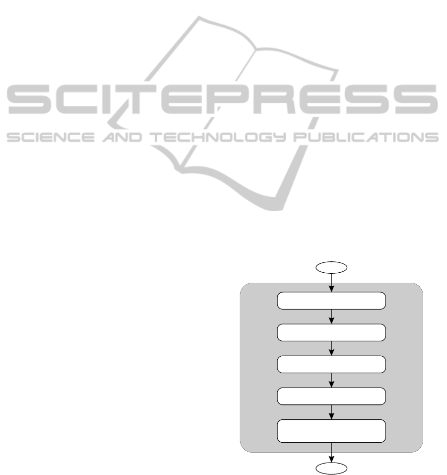
2002). The block diagram of the optimization
procedure is shown in Fig. 1. More detailed
explanation of the optimization algorithm can be
found in (Koziel and Ogurtsov, 2013).
2.3 Design Space Reduction Algorithm
Response surface approximation model R
s
, once set
up, is very fast and easy to optimize; however the
cost of gathering training data for its construction
increases exponentially with the number of design
variables, which makes utilization of such a model
questionable if the number of antenna geometry
parameters is larger than 5 or 6 (Bekasiewicz et al.,
2014b; Koziel and Ogurtsov, 2013). Consequently,
the reduction of the design space is a crucial step to
make the RSA model setup feasible.
The Pareto optimal-set is usually located in a
small region of the initially defined design space:
normally, the frontiers for each geometry parameter
of an antenna are defined rather wide to ensure that
the desired solutions are located within these
prescribed limits.
Figure 1: Design flow of the proposed multi-objective
optimization procedure.
START
Reduce design space
Refine selected designs
using SBO
END
Acquire data
R
cd
Construct kriging model
R
s
Optimize using MOEA
R
s
SIMULTECH2014-4thInternationalConferenceonSimulationandModelingMethodologies,Technologiesand
Applications
800
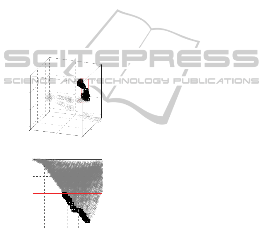
Figure 2 shows a typical example of such a
situation, here, for a UWB monopole antenna
(Bekasiewicz et al., 2014c). Nonetheless, setting up
the RSA model in such a large solution spaces is
virtually impractical. In the proposed approach,
frontiers of the solution space are reduced using
single-objective optimizations with respect to each
design goal. Consider l and u as initial lower/upper
bounds for the design variables. Let
*( )
arg min ( )
k
cd k cd
F
lxu
xRx
(2)
where k = 1, … N
obj
, is an optimal design of the low
fidelity-model R
cd
with respect to the kth objective.
These extreme (or corner) points of the Pareto
optimal-set are denoted by x
cd
*(k)
. Frontiers of the
reduced design space can be then defined as follows:
(a)
(b)
Figure 2: (a) Visualization of the Pareto optimal set (○) in 3-
dimensional solution space (data for UWB monopole
antenna, Bekasiewicz et al., 2014). The portion of the design
space that contains the part of the Pareto set we are interested
in (red cuboid, where F
1
≤ –10) is only a small fraction of the
initial space. (b) the Pareto set of interest (□) versus the entire
design space mapped to the feature space (×).
l* = min{x
cd
*(1)
, …, x
cd
*(Nobj)
} (3)
u* = min{x
cd
*(1)
, …, x
cd
*(Nobj)
} (4)
The reduced solution space is usually orders of
magnitude (volume-wise) smaller than the initial
one, which makes the generation of an accurate RSA
model possible at a low computational expense. One
should note that utilization of the proposed method
cannot ensure the existence of all Pareto optimal
solutions within refined design space; however, the
majority of them are usually accounted for.
3 CASE STUDY: PLANAR
YAGI-UDA ANTENNA
In order to demonstrate the presented design
concepts, let us consider a planar Yagi-Uda antenna
shown in Fig. 3. The antenna is designed to work on
Taconic RF-35 substrate (ε
r
= 3.5, tanδ = 0.0018, h =
0.762 mm). The structure is an extended version of
antenna discussed in (Qian et al., 1998) and it
comprises a driven element feed by a microstrip-to-
coplanar strip transition, three directors and a
microstrip balun. The input impedance is 50 Ω. In
the design process, the following two objectives are
considered:
F
1
– minimization of VSWR (with the maximum
allowed VSWR equal to 2 for the entire
frequency range of interest, here, 5.2 GHz to 5.8
GHz), and
F
2
– maximization of average gain in 5.2 GHz to
5.8 GHz frequency range.
The antenna geometry is described by 12
parameters: x = [s
1
s
2
s
3
s
4
v
1
v
2
v
3
v
4
u
1
u
2
u
3
u
4
]
T
.
Parameters w
1
= 1.7, w
2
= 3, w
3
= 0.85 and w
4
= 0.85
remain fixed (all dimensions in mm). The high-
fidelity model R
f
of the antenna (~600,000 mesh
cells, average evaluation time of 25 minutes) and its
low-fidelity counterpart R
cd
(~110,000 mesh cells,
evaluation time of 150 seconds) are both
implemented in CST Microwave Studio (CST, 2013)
and evaluated using its transient solver. The initial
lower/upper bounds are l = [2 2 2 2 18 7 7 7 3 7 2
1]
T
, and u = [10 10 10 10 30 15 15 15 12 16 6 3]
T
.
4 OPTIMIZATION RESULTS
In the first stage of the design process, the technique
described in Section 2.3 has been applied to
determine the reduced search space boundaries:
0
2
4
5
10
15
5
10
15
20
y
x
z
5 10 15 20 25 30 35
-20
-15
-10
-5
0
F
2
F
1
ComputationallyEfficientMulti-ObjectiveOptimizationofandExperimentalValidationofYagi-UdaAntenna
801
l
*
= [4.05 3.75 2.93 2 22.89 13 14.6 8 4.93 12.34 4.2
1.96]
T
, and u
*
= [7.39 9.75 8.93 10 24.22 15 14.6 15
8.93 13.01 4.2 2.62]
T
. Compared to the initial
bounds, a five orders of magnitude reduction
(volume-wise) has been obtained.
In the next stage, the response surface
approximation model was constructed using 1300
R
cd
training samples allocated by means of Latin
Hypercube Sampling (Beachkofski and Grandhi,
2002). The generalization error of the model
estimated using cross-validation (Queipo et al.,
2005) is only 1% for VSVR and 0.1% for gain. It
should be reiterated that it is not possible to
construct such accurate RSA models in the original
design space unless significantly larger number of
training samples are utilized.
The initial Pareto optimal set has been identified
using multi-objective evolutionary algorithm applied
to the surrogate model R
s
. In the last stage, a set of
ten designs has been selected from the initial Pareto
set and refined using the procedure described in
Section 2.2. The results are shown in Table 1
(detailed antenna dimensions for the selected
designs) and Fig. 4 (initial and refined Pareto sets).
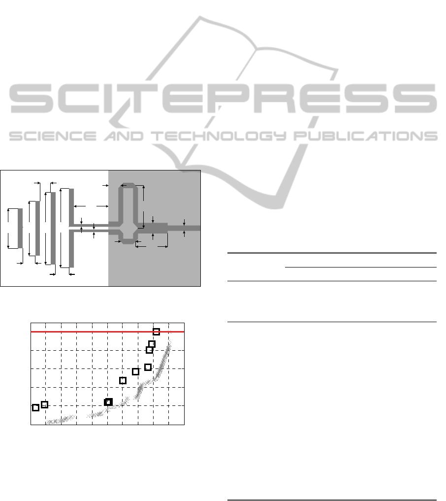
Figure 3: Layout of 12-variable planar Yagi-Uda antenna.
Figure 4: Pareto set of optimized RSA model R
s
(×)
obtained by the proposed multi-objective optimization
procedure and 11 refined high-fidelity designs R
f
(□)
obtained by (1).
It can be observed that the minimum antenna
VSVR is 1.177 (with the corresponding average gain
of 6.47 dB). The maximum average gain possible for
this antenna is 8 dB while still maintaining the
VSVR level of 2 within the entire frequency band of
interest. Figure 5 shows the frequency responses of
the antenna for a few designs selected along the
Pareto set.
It is interesting to analyse the cost of multi-
objective antenna design using the proposed
technique. In the first stage (design space reduction),
334 R
cd
evaluations were used to execute single-
objective evaluations (220 R
cd
and 114 R
cd
evaluations for minimization of F
1
and
maximization of F
2
, respectively). The response
surface approximation model was constructed using
additional 1300 R
cd
samples. Multi-objective
optimization of the RSA model is a very fast
process, the cost of which corresponds to less than
one high-fidelity model evaluation. Finally, the
refinement step requires 30 R
f
evaluations. The total
aggregated cost of Yagi-Uda antenna optimization is
about 194 R
f
simulations (~81 hours of CPU time),
which is very low compared to direct multi-objective
optimization using population-based metaheuristic,
the latter requiring at least a few thousands of high-
fidelity model evaluations (estimated using the
number of evaluations of R
s
model during MOEA
optimization).
Table 1: Multi-objective optimization results for planar
Yagi-Uda antenna.
Selected designs
x
f
(1)
x
f
(3)
x
f
(5)
x
f
(8)
x
f
(10)
VSVR 1.177 1.240 1.573 1.801 2.003
Average gain
[dB]
6.472 7.425 7.771 7.957 8.041
Design variables [mm]
s
1
7.38 6.19 6.03 4.87 4.30
s
2
3.79 3.82 7.57 9.46 9.75
s
3
3.08 7.24 6.94 8.10 8.44
s
4
9.41 9.61 9.75 9.98 9.92
v
1
24.03 23.96 23.00 23.03 22.96
v
2
14.65 14.95 14.97 14.92 14.99
v
3
14.60 14.60 14.60 14.60 14.60
v
4
11.52 14.81 14.78 15.00 15.00
u
1
8.08 7.36 5.49 5.44 5.11
u
2
12.36 12.39 12.40 12.35 12.34
u
3
4.20 4.20 4.20 4.20 4.20
u
4
2.24 2.59 1.98 2.01 2.35
w
1
w
2
u
1
u
2
u
3
u
4
w
3
w
4
s
1
v
4
v
1
GND
s
2
s
3
s
4
v
2
v
3
6.4 6.6 6.8 7 7.2 7.4 7.6 7.8 8 8.2 8.4
1
1.2
1.4
1.6
1.8
2
F
2
(Average Gain) [dB]
F
1
(max(VSWR) in band)
SIMULTECH2014-4thInternationalConferenceonSimulationandModelingMethodologies,Technologiesand
Applications
802
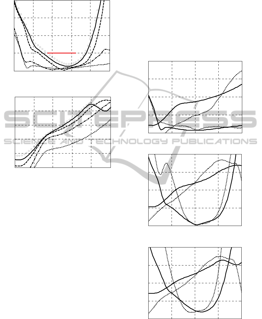
(a)
(b)
Figure 5: Frequency characteristics of the designs from
Table I: x
f
(1)
– (···), x
f
(3)
– (– · –), x
f
(5)
– (– – –),x
f
(8)
– (–––),
x
f
(10)
– (○○○).
It should be emphasized that multi-objective
optimization is essential to obtain comprehensive
information about the structure under design, here,
the considered Yagi-Uda antenna. The knowledge
about possible trade-offs between conflicting
objectives is fundamental for making design
decisions, in particular selecting the antenna
structure for a particular application. The proposed
technique allows us to gather this information at a
low computational cost and it is doable on a single-
processor machine in hours rather than weeks (the
latter typical for metaheuristic-based optimization,
see, e.g., Chamaani et al., 2011).
5 EXPERIMENTAL
VALIDATION
Selected antenna designs (x
f
(1)
, x
f
(5)
, x
f
(10)
– see Table
1 for dimensions) have been fabricated in order to
carry out experimental verification of the proposed
multi-objective design and optimization technique.
Both, reflection and gain have been measured using
vector network analyser. The latter has been
determined using three antenna method based on
Friis transmission equation (Balanis, 2005). A
comparison of simulation and measurement results
is shown in Fig. 6, whereas a photograph of the
fabricated circuits is shown in Fig. 7.
(a)
(b)
(c)
Figure 6: Simulation (—) and measurement (···) results of
optimized Yagi-Uda antennas in terms of voltage standing
wave ratio and gain: (a) x
f
(1)
; (b) x
f
(5)
; (c) x
f
(10)
.
4.5 4.9 5.3 5.7 6.1 6.5
1
2
3
4
5
VSWR
Frequen cy [GHz]
4.5 4.9 5.3 5.7 6.1 6.5
5
6
7
8
9
10
Gain [dB]
Frequen cy [GHz]
4.5 5 5.5 6 6.5
1
2
3
4
5
Frequency [GHz]
VSWR
3
5
7
9
11
Gain [dB]
4.5 5 5.5 6 6.5
3
5
7
9
11
Gain [dB]
4.5 5 5.5 6 6.5
1
2
3
4
5
Frequency [GHz]
VSWR
3
5
7
9
11
Gain [dB]
4.5 5 5.5 6 6.5
3
5
7
9
11
Gain [dB]
4.5 5 5.5 6 6.5
1
2
3
4
5
Frequency [GHz]
VSWR
3
5
7
9
11
Gain [dB]
4.5 5 5.5 6 6.5
3
5
7
9
11
Gain [dB]
ComputationallyEfficientMulti-ObjectiveOptimizationofandExperimentalValidationofYagi-UdaAntenna
803
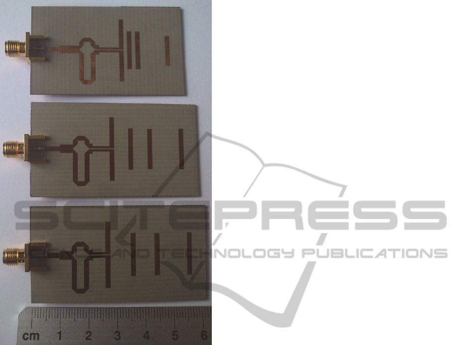
Figure 7: Photograph of a fabricated antennas, from the
top: x
f
(1)
, x
f
(5)
, x
f
(10)
.
A slight difference in VSWR factor can be
observed for x
f
(5)
and x
f
(10)
antenna realizations,
which is due to the lack of connector in the EM
antenna model. Slight differences between gain
responses can also be observed. They are introduced
by impedance and polarization matching errors
during measurement procedure.
6 CONCLUSIONS
In this work, a simple yet robust and
computationally efficient technique for multi-
objective optimization of multi-parameter Yagi-Uda
antenna has been presented. Our approach exploits
variable-fidelity EM simulations and a response
surface approximation (RSA) model (here, realized
as kriging interpolation). An important step of the
process, i.e., initial reduction of the design space,
allows for constructing the RSA surrogate using a
limited number of training samples, even though the
number of designable parameters is relatively large.
The Pareto optimal-set is obtained at a cost of less
than 200 high-fidelity model evaluations, which is a
considerable speedup in comparison to direct multi-
objective optimization using population-based
metaheuristics. The selected designs have been
fabricated and measured for the sake of an additional
validation of the design procedure.
ACKNOWLEDGEMENTS
The authors thank Computer Simulation Technology
AG, Darmstadt, Germany, for making CST
Microwave Studio available. This work was
supported in part by the Icelandic Centre for Research
(RANNIS) Grant 141272051.
REFERENCES
Afshinmanesh, F., Marandi, A., Shahabadi, M. 2008.
Design of a Single-Feed Dual-Band Dual-Polarized
Printed Microstrip Antenna Using a Boolean Particle
Swarm Optimization. In IEEE Transactions on
Antennas and Propagation, 56, 1845—1852.
Balanis, C.A. 2005. Antenna theory: analysis and design.
John Wiley & Sons, 3
rd
edition.
Bandler, J.W., Cheng, Q.S., Dakroury, S.A., Mohamed,
A.S., Bakr, M.H., Madsen, K., Søndergaard, J. 2004.
Space mapping: the state of the art. In IEEE
Transactions on Microwave Theory and Techniques,
52, 337—361.
Beachkofski, B., Grandhi, R. 2002 Improved distributed
hypercube sampling. In American Institute of
Aeronautics and Astronautics, paper AIAA 2002-
1274.
Bekasiewicz, A., Koziel, S., Leifsson, L. 2014. Low-cost
EM-simulation-driven multi-fidelity optimization of
antennas. In International Conference on
Computational Science – Procedia Computer Science,
29, 769—778.
Bekasiewicz, A., Koziel, S., Zieniutycz, W. 2014. Design
Space Reduction for Expedited Multi-Objective
Design Optimization of Antennas in Highly-
Dimensional Spaces. In Solving Computationally
Extensive Engineering Problems: Methods and
Applications.
Bekasiewicz, A., Koziel, S., Ogurtsov, S., Zieniutycz, W.
2014. Design of Microstrip Antenna Subarrays: A
Simulation-Driven Surrogate-Based Approach. In
International Conference on Microwave Radar and
Wireless Communications, 1, 177—180.
Chamaani, S., Mirtaheri, S.A., Abrishamian, M.S. 2011.
Improvement of Time and Frequency Domain
Performance of Antipodal Vivaldi Antenna Using
SIMULTECH2014-4thInternationalConferenceonSimulationandModelingMethodologies,Technologiesand
Applications
804

Multi-Objective Particle Swarm Optimization. In
IEEE Transactions on Antennas and Propagation, 59,
1738—1742.
Conn, A.R., Scheinberg, K., Vicente, L.N. 2009.
Introduction to Derivative-Free Optimization. In MPS-
SIAM Series on Optimization, MPS-SIAM.
CST Microwave Studio 2013. Computer Simulation
Technology AG, Bad Nauheimer Str. 19, D-64289
Darmstadt, Germany.
Deb., K. 2001. Multi-Objective Optimization Using
Evolutionary Algorithms. John Wiley & Sons. New
York.
Ding, D., Wang, G. 2013. Modified Multiobjective
Evolutionary Algorithm Based on Decomposition for
Antenna Design. In IEEE Transactions on Antennas
and Propagation, 61, 5301—5307.
Jin, N. Rahmat-Samii, Y., 2007. Advances in Particle
Swarm Optimization for Antenna Designs: Real-
Number, Binary, Single-Objective and Multiobjective
Implementations. In IEEE Transactions on Antennas
and Propagation, 55, 556—567.
Jin, N., Rahmat-Samii, Y. 2010. Hybrid Real-Binary
Particle Swarm Optimization (HPSO) in Engineering
Electromagnetics. In IEEE Transactions on Antennas
and Propagation, 58, 3786—3794.
Junwei L., Ireland, D., Lewis, A. 2009 Multi-Objective
Optimization in High Frequency Electromagnetics—
An Effective Technique for Smart Mobile Terminal
Antenna (SMTA) Design. In IEEE Transactions on
Magnetics, 45, 1072—1075.
Kolundzija, B.M., Olcan, D.I. 2006. Multiminima
heuristic methods for antenna optimization. In IEEE
Transactions on Antennas and Propagation, 54,
1405—1415.
Koulouridis, S., Psychoudakis, D., Volakis, J. 2007.
Multiobjective Optimal Antenna Design Based on
Volumetric Material Optimization. In IEEE
Transactions on Antennas and Propagation, 55, 594—
603.
Koziel, S., Cheng, Q.S., Bandler, J.W. 2008. Space
mapping. In IEEE Microwave Magazine, 9, 105—122.
Koziel, S., Bandler, J.W. 2012. Accurate modeling of
microwave devices using kriging-corrected space
mapping surrogates. In International Journal of
Numerical Modelling: Electronic Networks, Devices
and Fields, 25, 1—14.
Koziel, S., Ogurtsov, S. 2013. Multi-Objective Design of
Antennas Using Variable-Fidelity Simulations and
Surrogate Models. In IEEE Transactions on Antennas
and Propagation, 61, 5931—5939.
Koziel, S., Leifsson, L., Ogurtsov, S. 2013. Reliable EM-
driven microwave design optimization using manifold
mapping and adjoint sensitivity. In Microwave and
Optical Technology Letters, 55, 809—813.
Koziel, S., Ogurtsov, S., Couckuyt, I., and Dhaene, T.
2013. Variable-Fidelity Elec-tromagnetic Simulations
and Co-Kriging for AccurateModeling of Antennas. In
IEEE Transactions on Antennas and Propagation, 61,
1301—1308.
Koziel, S., Bekasiewicz, A., Zieniutycz, W. 2014 Expedite
EM-Driven Multi-Objective Antenna Design in
Highly-Dimensional Parameter Spaces. In IEEE
Antennas and Wireless Propagation Letters, 13, 631—
634.
Kuwahara, Y. 2005. Multiobjective optimization design of
Yagi-Uda antenna. In IEEE Transactions on Antennas
and Propagation, 53, 1984—1992.
Nocedal, J., Wright, S. 2006. Numerical optimization,
Springer, 2
nd
edition.
Lophaven, S.N., Nielsen, H.B., Søndergaard, J. 2002
DACE: a Matlab kriging toolbox, Technical
University of Denmark.
Qian, Y., Deal, W.R., Kaneda, N., Itoh, T. 1998.
Microstrip-fed quasi-Yagi antenna with broadband
characteristics. In Electronics Letters, 34, 2194—
2196.
Queipo, N.V., Haftka, R.T., Shyy, W., Goel, T.,
Vaidynathan, R., Tucker, P.K. 2005 Surrogate-based
analysis and optimization. In Progress in Aerospace
Sciences, 41, 1—28.
Sharaqa, A., Dib, N. 2013. Position-only side lobe
reduction of a uniformly excited elliptical antenna
array using evolutionary algorithms. In IET
Microwaves, Antennas & Propagation, 7, 452—457.
Simpson, T.W., Peplinski, J., Koch, P.N., Allen, J.K.
2001. Metamodels for computer-based engineering
design: survey and recommendations. In Engineering
with Computers, 17, 129—150.
Talbi, E.-G. 2009. Metaheuristics – From Design to
Implementation. John Wiley & Sons.
Yang, X.-S., Ng, K.-T. Yeung, S.H., Man, K.F. 2008.
Jumping Genes Multiobjective Optimization Scheme
for Planar Monopole Ultrawideband Antenna. In IEEE
Transactions on Antennas and Propagation, 56,
3659—3666.
ComputationallyEfficientMulti-ObjectiveOptimizationofandExperimentalValidationofYagi-UdaAntenna
805
