
Transformation of DEMO Model into Coloured Petri Net
Ontology based Simulation
Tarek Fatyani, Junich Iijima and Jaehyun Park
Department of Industrial Engineering and Management, Graduate School of Decision Science and Technology,
Tokyo Institute of Technology, Tokyo, Japan
Keywords: DEMO Model, Modelling and Simulation, Petri Net (PN), Coloured Petri Net (CPN), Business Process
Simulation.
Abstract: Enterprises are growing in complexity due to many business processes. This growth requires a simple but
complete model for enterprise design. The DEMO model has proven its ability to describe an enterprise in a
concise, coherent, and complete manner over the last decade. However, validating the model in the real
world requires methods that enable debugging and testing the model, which can be achieved by simulating
the model. In this paper, a simulation methodology is proposed. The methodology is based on mapping one
to one from the DEMO model to Coloured Petri Net. The reason for choosing CPN is to use the richness of
the Petri Net research results on, e.g., performance, deadlock analysis, animation, etc. Furthermore, CPN
has a mathematical representation, which can initiate research on analysing DEMO models mathematically.
As for validation, this paper applied the proposed transformation method to a case study.
1 INTRODUCTION
Enterprises are growing in complexity due to the
existence of many business processes that form an
interwoven network of business transactions. To
design and re-engineer such an enterprise, a
conceptual model of the enterprise is needed. In
recent decades, many modelling methodologies have
been developed. Among those methodologies is
DEMO. Design and Engineering Methodology for
Organizations (DEMO) is a methodology for the
design and engineering of organizations. DEMO is a
concise and coherent model that illustrates the
essence of an organization (Dietz, 2006). However,
DEMO lacks tools that support the simulation of its
models. DEMO Simulation provides a powerful tool
to validate the proposed DEMO model compared to
the real world by running, debugging and analysing
the model. Deadlocks or any unpredicted roots can
be discovered during the simulation. Furthermore,
simulating DEMO models may answer “what if”
questions, which may be a useful tool for re-
engineering the enterprise. Additionally, Petri net is
a simple modelling language used to model and
analyse concurrent systems. Its simplicity and
simulation capability make it appealing for many
other modelling languages. They transfer their
model into PN to utilize its features, e.g., Activity
Diagram and BPMN. However, the usefulness of the
simulation model depends on the quality of the
original conceptual model like AM or BPMN. And
if those models don’t represent the ontology of the
enterprise, then the quality of the simulation models
will be low. Therefore, an ontology conceptual
model is needed as a base to do the simulation. We
call it here ontology based simulation. By analysing
PN and DEMO models, the similarity between the
two is clear. The concepts of Fact and Act in DEMO
model can be perfectly mapped to the concepts of
Place and Transition in PN. This similarity creates
the potential to map DEMO to PN, which is useful
not only for simulating DEMO models but also for
utilizing the richness of research and analysis that
are conducted on PN, as well as other tools that have
been developed for those purposes. Therefore, in this
paper, a transformation methodology from DEMO to
Coloured Petri Net is introduced. The transformation
mainly focuses on the Process Model (PM) of
DEMO, because PM describes the dynamics of the
enterprise as a workflow and is used to create the
Basic Petri Net. However, the State Model (SM),
and the Action Model (AM) of DEMO are also used
to define the Color Sets, Guards, Variables and
Expressions in CPN. The potential benefits from
388
Fatyani T., Iijima J. and Park J..
Transformation of DEMO Model into Coloured Petri Net - Ontology based Simulation.
DOI: 10.5220/0005137803880396
In Proceedings of the International Conference on Knowledge Engineering and Ontology Development (KEOD-2014), pages 388-396
ISBN: 978-989-758-049-9
Copyright
c
2014 SCITEPRESS (Science and Technology Publications, Lda.)

transforming DEMO into CPN can be summarized
as follows: first, CPN is based on Petri net, which
can be used for simulation. Therefore, the
transferred model can be used to simulate the
DEMO models. Second, CPN is an old and simple
process modelling language that provides a lot of
expertise and tools that can be used for analysis of
its models. Third, CPN has a mathematical
representation that can lead to interesting research
that analyses DEMO models mathematically.
Reasons for choosing Coloured Petri Net include its
ability to capture the cardinality in DEMO and its
ability to program the business rules in the AM of
DEMO by constructing the Guards and Expressions
in CPN. Therefore, the main contribution of this
paper is the transformation of the DEMO model into
CPN and showing the validity of our
transformational approach by implementing one case
study. The remainder of this paper is organized as
follows. First, we address the literature review,
covering the features of the DEMO Model and Petri
Net. Then, the transforming methodology will be
introduced. To validate the proposed method, a case
study will follow this methodology. Finally, in the
last chapter, the conclusion and the discussion are
addressed with the results and the future work.
2 LITERATURE REVIEW
2.1 DEMO Model
DEMO is short for “Design and Engineering
Methodology for Organizations”. This methodology
is based on the PSI-theory (Performance in Social
Interaction). It shows that any transaction within an
enterprise is performed via the interaction of two
actors (actor roles) in which one plays the role of
initiator of the transaction and other plays the role of
the executor (Alicia, Perinforma, 2012).
It is said that DEMO has the following benefits:
Essential, coherent, consistent, complete and
modular. (The Enterprise Engineering Institute,
2014).
DEMO consists of four models which are the
CM (Construction Model), PM (Process Model), FM
(Fact Model) and AM (Action Model). PM describes
the sequences of process steps. Therefore, PM
describe the dynamics of the enterprise. The PM is
represented by a PSD (Process Structure Diagram)
and a TPD (Transaction Pattern Diagram). While
these four models present rich information about an
enterprise, none of these models can be directly
simulated to study the dynamic behaviour of
processes or an enterprise as a whole. By creating
models, analysts can better conduct model validation
and obtain insight into the dynamic behaviour of
systems (Barjis, 2007). To accomplish this task and
for enterprise reengineering, a simulation tool is
needed to validate the DEMO model.
Using Enterprise Ontology to drive the
engineering of enterprise information system has
been proposed. A DEMO processor has been
developed as a software engine for model
development, model simulation and validation
(Steven, Dietz, Hintzen, Meeuwen, Zijlstra, 2012).
However, for the purpose of validating DEMO
models and optimizing the workflow, many tools
must be developed. There are many tools that are
used to simulate the workflow and analyse it, such
as Petri Net (PN). Transforming DEMO models into
CPN allows us to use all of these tools and that
expertise that already exists and is used in the
market.
2.2 Petri Net
A Petri Net is one of the modelling languages for the
description of distributed systems. The modelling
languages of Petri Net consist of transitions
represented by rectangle, places represented by
circles, and edges that connect the transitions with
the places. Places act like a pre/post condition for
transition.
(Marwan, Rohr, Heiner, 2012).
Definition 1. A Petri net is a triple N = (P, T, F)
where:
P and T are disjoint finite sets of places and
transitions, respectively.
⊂∪ is a set of arcs (or flow
relations).
Petri Net has the following features (Valk, Girault,
2003) (Liu, Heiner, Rohr, 2012):
Representations: Petri Net has both a
graphical and mathematical representation that
can be used for modelling and analysing the
systems;
Verification: There are many algorithms for
verifying the model as well as tools for
analysing Petri Net models, and these
algorithms are supported by many powerful
computer tools;
Hierarchy: Petri Net has the ability for form
abstractions and hierarchical designs, which is
a crucial factor for the effective design of
complex systems. There are many
mechanisms for abstraction and refinement
that can be used for modelling systems;
Expertise: Because Petri Nets have been used
TransformationofDEMOModelintoColouredPetriNet-OntologybasedSimulation
389

in many different application areas, there is a
high degree of expertise in the modelling
field. Some examples would be
manufacturing, workflow management,
telecommunications and biology;
Varity: There are different variants of Petri
Net models that have been developed to suit
different applications, such as Coloured Petri
Net (CPN) and Stochastic Petri Net;
Simulation: Petri Net can be simulated, and it
has many tools for simulation. Therefore, it is
possible to perform many experiments using
the model and then analyse the results;
Demonstration: Above all, the simulation
ability of Petri Net makes it useful as a good
demonstration for the stakeholders to achieve
a common understanding about the model.
There is a subclass of Petri net called workflow
nets (WF nets) that is used for modelling and
simulating business process and workflow. WF nets
can be defined as follow:
Definition 2. (Van Der Aalst, 2000) A Petri net
PN= (P, T, F) is a WF-net if and only if:
1. There is one source place i ϵ P such that •i=
∅
2. There is one sink place o ϵ P such that o•=
∅
3. Every node x ϵ P
∪
T is on a path from i to o
, where •i is the set of transitions sharing i as output
place, and o• e is the set of transitions sharing o as
input place. And there are many concepts and
criteria that have been developed for the purpose of
verification of WF nets. One of the most important
criteria is that of soundness.
Definition 3. (Van Der Aalst, Van Hee, Ter
Hofstede, Sidorova, Verbeek, Voorhoeve, Wynn,
2011) A WF-net is sound if and only if:
1. For every state M reachable from state i, there
exists a firing sequence leading from state M to
state o.
2. State o is the only state reachable from state i
with at least one token in place o.
3. There are no dead transitions (transition that
can never fire)
In this paper, we use Coloured Petri Net to
capture the cardinality in DEMO and the business
rules in Action Model.
Definition 4. A Coloured Petri Net is a tuple N =
(P, T, F, Σ, C, N, E, G, I ) where:
P is a set of places.
T is a set of transitions.
F is a set of arcs
Σ is a set of color sets defined within CPN
model. This set contains all possible colors,
operations and functions used within CPN.
C is a color function. It maps places in P
into colors in Σ.
N is a node function. It maps F into P ×
T
∪
T × P.
E is an arc expression function. It maps
each arc f
∈
F into the expression e. The
input and output types of the arc expressions
must correspond to type of nodes the arc
connected to.
G is a guard function. It maps each
transition t
∈
T into guard expression g. The
output of the guard expression should
evaluate to Boolean value true or false.
I is an initialization function. It maps each
place p into an initialization expression i.
The initialization expression must evaluate
to multiset of tokens with a color
corresponding to the color of the place C(p).
Despite all of these features of Petri Net, many
other modelling methods are used to describe the
system, such as AD (Activity Diagram in UML) and
BPMN (Business Process Modelling Notation), even
they do not have a tool for simulation like Petri Net.
The reason for this discrepancy is that these types of
modelling methodologies have more representation
elements using graphical representations, which can
be easily understood by stakeholders, unlike Petri
Net, which has only transitions and places (Weske,
2012).
In fact, many researchers have proposed a
transformation methodology from different models,
such as AD and BPMN into Petri Net, as described
below. Furthermore, PN lacks the ontology concept
in modelling. Without the ontological concept,
models could be very complex and lack the
consistency and the completeness that DEMO has.
From the previous paragraph we can conclude that
DEMO and Petri Net together can construct a
perfect methodology for modelling and simulating
the enterprise.
2.3 Transforming BP Models into Petri
Nets
There are several studies on transforming different
business modelling languages to PN. For example,
AD is a diagram that can express the most desirable
routing constructs, but it has no defined semantics
that are used for workflow modelling. A
transformation of AD into Petri Net allows for
model checking for verification and validation
purposes. Other studies have been performed for the
purpose of evaluating non-functional parameters of a
software system in the design stages using
KEOD2014-InternationalConferenceonKnowledgeEngineeringandOntologyDevelopment
390

Generalized Stochastic Petri Net that has been
transferred from the AD model (Eshuis, Wieringa,
2003) (Motameni, Movaghar, Fadavi Amiri, 2007)
(Staines, 2008)
.
Other research has been conducted for
transforming BPMN into Petri Net to check the
semantic correctness of the models statistically
(Remco, Marlon, Chun, 2008).
Based on the previous research, we can see that
many studies have developed methodologies for
transforming a business process model into PN.
However, DEMO dose not has this transformation
yet, which is introduced in this research. Previous
research proposed a simulation of DEMO using the
Standard Petri Net. However, the full transformation
that includes all of the transaction patterns is not
developed. In this research, a full transformation
methodology from the Process Model of DEMO into
PN is introduced for the three transaction patterns
(basic, standard and complete). In addition,
Coloured Petri Net is proposed for describing the
cardinality of the DEMO model. Furthermore, the
business rules that are described in the Action Model
of DEMO can be programmed in Coloured Petri Net
(Barjis, 2007).
3 TRANSFORMATION
METHODOLOGY
Figure 1: Business Process Optimization based on DEMO
and CPN.
In Figure 1, the conceptual idea of the
transformation is presented. After creating the CPN
model from the DEMO model, a configuration is
needed to specify the instances that are required for
simulation, as shown in the design phase. After the
configuration, the simulation is conducted. CPN can
be simulated interactively or automatically. The
interactive simulation is a single-step debugging.
This method is used to validate the model. In
addition, this method was used in the case study
presented in this paper. It provides a way to “walk
through” or investigate the different scenarios in
detail and determine if the model works as expected.
The second one is the automatic method, which is
used for performance analysis.
Figure 2: Transforming DEMO to CPN.
In this paper, each aspect of the DEMO model
will be mapped to CPN (except CM). The DEMO
model consists of four aspect models: a Construction
Model (CM), Process Model (PM), State Model
(SM) and Action Model (AM). The CM provides a
general view of the enterprise by showing the
transactions related to the actor roles. The PM
provides more details about the process steps
between the transactions. Therefore, the Basic Petri
Net (BPN) can be constructed based on the PM. The
BPN consists of Place, Transition and Edge. The SM
illustrates the object classes with their properties.
These classes and their properties will form the
Color Sets in the CPN. Finally, the AM presents the
business rules. These business rules govern the
actions between the process steps and will be created
in the CPN using the Transition Guards (G) and
Edge Expressions (E), which is shown in Figure 2.
To illustrate the transformation from DEMO to
CPN, the CPN model of transaction will be
presented for the standard transaction pattern and for
the complete transaction pattern.
3.1 Standard Transaction Pattern
Petri net has three basic elements place, transition
and edge. Initiate, C-fact, Discussion status and P-
fact in DEMO will be replaced by Place in Petri Net
because the Fact and Status in DEMO represent a
particular status of an instance. This concept is
perfectly matched with the concept of Place in Petri
Net. The C-fact and P-fact in DEMO have no
difference in Petri Net because both of them are
replaced by a Place. The Acts in DEMO (both C-act
and P-act) can be replaced by Transitions in Petri
Net because the concept of an Act in DEMO
represents a change in the status of an instance,
which can be matched perfectly by the concept of a
TransformationofDEMOModelintoColouredPetriNet-OntologybasedSimulation
391
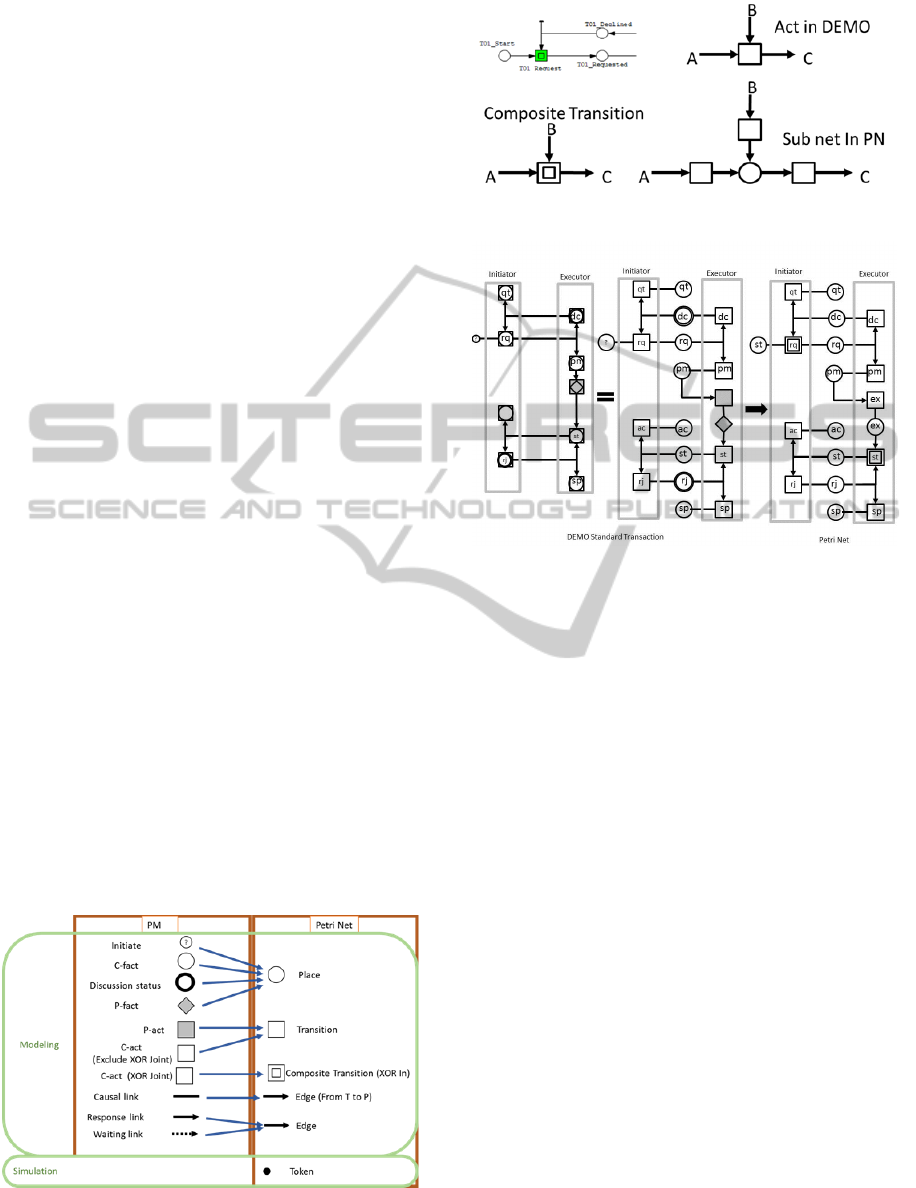
Transition in Petri Net, as shown in Figure 3. All of
the types of links in DEMO will be replaced by
Edges in Petri Net. In the case of a Causal link (there
is no arrow), the arrow will be from the Transition to
the Place by default. When there is more than one
(In or Out) link for one transition in Petri Net, it is
handled as an And Joint. However, in DEMO there
might be an And Joint or a XOR joint. To solve this
issue, a composite transition is introduced, which is
illustrated in Figure 4. Petri net has three basic
elements place, transition and edge. Initiate, C-fact,
Discussion status and P-fact in DEMO will be
replaced by Place in Petri Net because the Fact and
Status in DEMO represent a particular status of an
instance. This concept is perfectly matched with the
concept of Place in Petri Net. The C-fact and P-fact
in DEMO have no difference in Petri Net because
both of them are replaced by a Place. The Acts in
DEMO (both C-act and P-act) can be replaced by
Transitions in Petri Net because the concept of an
Act in DEMO represents a change in the status of an
instance, which can be matched perfectly by the
concept of a Transition in Petri Net, as shown in
Figure 3. All of the types of links in DEMO will be
replaced by Edges in Petri Net. In the case of a
Causal link (there is no arrow), the arrow will be
from the Transition to the Place by default. When
there is more than one (In or Out) link for one
transition in Petri Net, it is handled as an And Joint.
However, in DEMO there might be an And Joint or
a XOR joint. To solve this issue, a composite
transition is introduced, which is illustrated in Figure
4. In the Standard Transaction Pattern, Rq and St
Transitions have two input arrow. In addition, they
have to act as XOR junction. Therefore, they are
represented by a composite transition that consists of
one place and three transitions. The Petri Net model
of the Standard Transaction Pattern is shown in
Figure 5.
Figure 3: Elements mapping from PM of DEMO to PN.
Figure 4: XOR joint In PN.
Figure 5: Petri Net model of the Standard Pattern
Transaction.
3.2 Complete Transaction Pattern
In the Complete Transaction Pattern, the revoked
process needs to be added to each request, promise,
state and accept. For each revoke, the revoke starts
by requesting the revoke (one transition and one
place). If the revoke is allowed, then the token
(which represent an instance) will be revoked and
sent to the previous process. The figure of the
complete transaction pattern will not be shown here
because of the number of pages limit.
3.3 Configuring the CPN Model of
DEMO
After transferring each transaction to the Petri Net
model, the links between the transactions can be
added to the Petri Net model. For instance, if there is
a link between promise at T1 and a request at T2, a
link is made from the promise transition of T1 to the
start of T2. In this step, the unnecessary process can
be deleted (reject and decline for example).
If the purpose of the simulation is to compare
many different possible flows, then many different
models (by adding or deleting the reject, decline and
revoke) can be constructed and compared. After
completing the model, a set of color sets can be
KEOD2014-InternationalConferenceonKnowledgeEngineeringandOntologyDevelopment
392

defined. These color set should represent the
properties that are to be measured in the simulation
results. For instance, if we want to measure the cost,
a cost color set can be added to the token in the
Coloured Petri Net. After the simulation, the result
for the cost can be analysed.
4 CASE STUDY
The following passage describes the case study that
will be used as an example for validating the
transformation methodology. This example has been
taken from analysing a typical fast food restaurant in
Syria. The description is as follows:
This passage is a description of a typical
sandwich restaurant in Syria. In this paper, it will be
referred as TSR (Typical Sandwich Restaurant). The
restaurant sells many different types of sandwiches
(Falafel, Shawarma ...). Customers can customize
their order by specifying the spices and the dressing
for their sandwiches. Customers come to the cash
register where they choose their order from the
menu, and if they want, they can specify customized
sandwiches according to their taste. The payment is
performed immediately at the cash register when
they order. After they have paid, they receive a
receipt that has all of the details of their order, and
then, the customer goes to the chef and gives him the
receipt. Some restaurants have automated this
process in such way that the order is automatically
shown on a display in front of the chef. In the
automated method, the customer receives a receipt
that has only the order number. Each order can
contain one or more sandwiches. Each sandwich is
made separately from the others. Therefore, the
order can be performed by only one worker or more
than one according to their availability. All of the
workers can do all of the tasks, including taking
orders, making sandwiches and giving the finished
order to the customers. Assigning the tasks to
workers is performed by the manager who needs to
always monitor the entire process and to adjust to
the situation, which means that if there are many
customers waiting for someone to take their order,
the manager will ask more than one worker to take
orders. However, if there is one large order (more
than 10 sandwiches) then he will assign more than
one workers to fulfil this order. After completing all
of the requested sandwiches, a worker collects them
together, puts them in a package and gives them to
the customer. To respond immediately to the
situation of the needed number of workers at each
section, the manager needs to construct a dashboard
that displays the current state of each section in one
model. In this dashboard, the number of waiting
customers and the reason for their wait (for example,
they are waiting for their sandwiches to be made, or
they are waiting for someone to take their orders…)
must be displayed. The status of each order has to be
displayed (for example, how many sandwiches have
been made and how many sandwiches have not yet
been made). This information should be displayed in
one model that alloys the manager to understand the
situation and respond to it as soon as possible. The
small changes in the work procedures should not
affect the model; otherwise, for each new procedure,
we may need a new model, which could cost a lot.
Based on the description, we can construct an
ATD (Action Transaction Diagram) using DEMO,
which is useful for understanding the ontological
aspects of the restaurant. ATD is the basic diagram
of DEMO that shows the ontological transactions
linked to the business roles: who are the initiators
and executors for these transactions. The ATD of the
TSR is shown in Figure 6. The first transaction is
(T1) purchase completion. The customer is the
initiator of this transaction (order sandwiches).
Because customer is considered an external actor
role, it is shaded CA1 (Composite Actor Role). The
executor of T1 is the A1 receptionist who takes the
order. The executor of any transaction is always
differentiated by the black dot on the link to its
transaction. The same actor role A1 is the initiator
for the second transaction T2 payment, because the
receptionist asks the customer to pay, and the
customer is the executor of T2 (has the black dot).
The third transaction is T3 making sandwiches. T3 is
an internal transaction because both the initiator A1
and the executor A2 are actor roles of the restaurant.
Based on this model, it is clear that the automation
of one process or a small change in the workflow
will have no influence on this model.
Figure 6: Actor Transaction Diagram of TSR.
ATD does not show the execution sequence of the
transactions. The sequence of transactions is
illustrated in the PSD (Process Structure Diagram).
The process starts by requesting the transaction T1
TransformationofDEMOModelintoColouredPetriNet-OntologybasedSimulation
393

by CA1. After promising T1 by A1, T2 is requested.
When the payment transaction T2 is accepted by A1,
T3 is requested by A1 (the cardinality number 1..n
means the number of sandwiches is more than or
equal to 1 and finite). Finally, when all of the
sandwiches are made, T1 can be executed after
accepting T3 by A1 and stated to the customer CA1.
In Figure 7, there are three links among transactions.
These links will be represented by red in Petri Net.
To get the CPN model of TSR, first each transaction
will be replaced by the suitable pattern that are
explained in section 3. Then the configuration need
to be set as it is explained in 3.3. The configuration
is explained in the following passage.
Figure 7: Process Structure Diagram of TSR.
5 DISCUSSION AND
CONCLUSION
5.1 Discussion
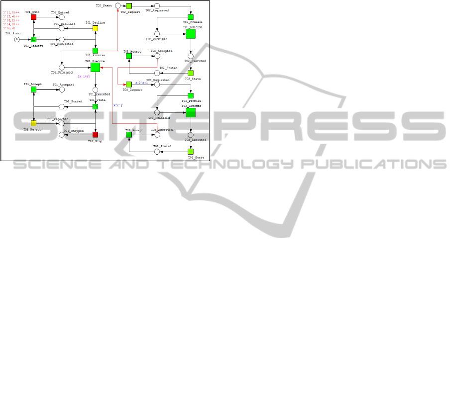
In Figure 8, the coloured Petri Net model of the TSR
is represented. Reject and decline at T2 and T3 have
been deleted because when the customer orders the
sandwiches, they already know about the prices, and
there is no room for declining or rejecting the
payment. The same is true for the making of the
sandwiches: there is no reason to not make the
sandwiches. If the purpose of the simulation is to
study the availability of raw materials, it is possible
to not be able to make the sandwiches and the
decline process must be added. In addition, the Quit
place must be connected to the revoke of promise at
T1, which is necessary to roll back the token to T1.
Two color sets have been defined for the tokens. The
first color set represents the ID of the order, which is
necessary to ensure that all of the sandwiches go to
the same order. The second color set represents the
number of the sandwiches, which is the cardinality
in T3. For example, if there is one order with three
sandwiches, then the token of the order will wait at
the promised place until its token (the sandwiches)
are accepted. After all of the sandwiches are
accepted, then the order can proceed to the execution
transition.
Another important point is the initiation of T3.
The case study shows that T3 starts after accepting
the payment at T2. However, it is not necessary to
wait for the payment. It can be started directly after
promising at T1. In this case, the acceptance of T2
will be linked to the execution of T1. By analysing
the resulted Petri Net model, the model fulfils the
three conditions of WF net. There is one source
place corresponds to the initial state (T1 Start). And
there are three possible sink places (T1_Accepted,
T1_Quitted and T1_Stopped). And each node is on
the path from the source place to one of the three
sink places. This could be easily seen by drawing the
State Space Graph in CPN Tools (Jensen, Kurt,
Kristensen, Lars, 2009). State Space Graph
represents all the possible state (marking) that the
system can be. Moreover, to test the soundness of
the model, we applied the Corollary 1 (Van Der
Aalst, 1995). Corollary 1 says “A BP-net PN is
sound if and only if (
,) is live and bounded”.
(
,) is the model and adding transitions to each
sink place to the source place. Therefore, three
transitions have been added to the model. Then by
analysing the new model using the CPN tools, it
shows that it is live and bound. This means the
original model is sound.
5.2 Conclusion
In this paper, we propose a methodology for
transforming models from DEMO to Coloured Petri
Net (CPN). The transformation of PM is formal and
can be programmed to any tool for automatic
transformation. The transformation is mainly based
on the PSD of DEMO; however, business rules in
the Action Model (AM) are included as well when
the links in CPN are programmed. It is important to
specify the cardinality in PSD. In PSD, the
cardinality is not always one to one. It is possible to
have a one-to-n token, which means that one token
from the first transaction will produce n tokens in
the second transaction. For example, one order may
have many sandwiches. The number of tokens
depends on the data value that the token has. A case
study of a typical sandwich restaurant was used to
validate this methodology. The CPN model of the
TSR was capable to capture the standard pattern
transaction as well as the basic pattern. Moreover,
KEOD2014-InternationalConferenceonKnowledgeEngineeringandOntologyDevelopment
394
the cardinality in DEMO model of TSR (number of
sandwiches) was represented in the CPN model of
TSR. This shows that this transformation
methodology overcomes the shortage of previous
research (capture all the patterns and the
cardinality). And the case study shows that the
methodology is valid for capturing those properties.
Figure 8: Coloured Petri Net model of TSR.
5.3 Contribution
is model can be considered a simulation based on a
DEMO model, and this simulation can be used for
any type of dynamic analysis. Some applications
include the analysis and study of resource allocation
problems, cost analysis, and the action time for each
process. This method could be used to optimize
business processes. The analyses that can be
conducted are structural and behavioural. There are
many tools for conducting these analyses on Petri
Net. All of them can be applied to analyse the
proposed model. Using this analysis, deadlocks can
be discovered and exceptional cases handled, such
as what if the transaction ends with a quit or stop.
Another contribution is that this model can be
used to independently explain the DEMO Model.
Despite the simplicity and conciseness of DEMO
Models, it is difficult for most unfamiliar people to
understand them, particularly for people who are
used to addressing typical process models. By using
this model, we can illustrate the DEMO Model using
animations and examples, which allows for easy
understanding of the important concepts of the
DEMO Model. In fact, this model provides more
insight into the enterprise and allows stakeholders to
interactively share their ideas about the problem,
which can lead to important discussions about the
problem and how to solve it. Furthermore, it can be
used to verify the constructed DEMO Model by
executing many examples and showing them to
experts.
5.4 Future Work
The presented model is mainly based on the PSD of
DEMO; however, we need to collect this
information from the Action Model of DEMO to
represent the conditions of the token movements.
These conditions have been considered to be
intuitive in this paper. However, they are not in the
formal transformation methodology. As a future
project, the business rules that are expressed in the
Action Model should be automatically addressed by
this model.
One potential for transforming this model to a
Petri Net Model is the possibility of taking
advantages of existing Petri Net analysis tools and
other tools to analyze the model.
An automatic transformation tool is needed to
make it easy to perform this transformation.
Petri Net has a mathematical representation,
which introduces many research possibilities for
analyzing DEMO models mathematically. These
possibilities can be studied in the future.
ACKNOWLEDGEMENTS
We would like to acknowledge the assistance of Dr.
Joseph Barjis. Without his continued efforts and
support, we would have not been able to bring this
work to a successful completion.
REFERENCES
Dietz, J. L. G., 2006. Enterprise Ontology Theory and
Methodology, Enterprise Ontology. Springer, Berlin,
Heidelberg.
The Enterprise Engineering Institute, 2014. [Online]
Available from: http://www.ee-institute.com/
methodology /. [Accessed Jan 2014].
Alicia P. C. Perinforma. 2012. The essence of organization
an introduction in enterprise engineering, Sapio bv.
Marwan, W., Rohr, C., Heiner, M., 2012. “Petri Nets in
Snoopy: A Unifying Framework for the Graphical
Display, Computational Modelling, and Simulation of
Bacterial Regulatory Networks,”Bacterial Molecular
Networks. Springer New York. Vol. 804, pp 409-437.
Valk, R., Girault, C., 2003. Petri Nets for Systems
Engineering, Springer, Berlin, Heidelberg.
Liu, F., Heiner, M., Rohr, C., 2012. Manual for Colored
Petri Nets in Snoopy, Brandenburg University of
Technology Cottbus, Report 02-12.
TransformationofDEMOModelintoColouredPetriNet-OntologybasedSimulation
395

Weske, M., 2012. Business Process Management:
Concepts, Languages, Architectures, Springer.
Eshuis, R., Wieringa, R., 2003. Comparing Petri Net and
Activity Diagram Variants for Workflow Modeling –a
Quest for Reactive Petri Nets. . In Petri Net
Technology for Communication-Based Systems, vol.
2472, pp. 321-351.
Motameni, H., Movaghar, A., Fadavi Amiri, M., 2007.
Mapping Activity Diagram to Petri Net, International
Journal of Engineering. Vols. 20 - 1, pp. 65-76.
Staines, T. S., 2008. Intuitive Mapping of UML 2 Activity
Diagrams into Fundamental Modeling Concept Petri
Net Diagrams and Colored Petri Nets. Engineering of
Computer Based Systems, pp. 191 - 200.
Remco, M. D., Marlon, D., Chun, O., 2008. Formal
Semantics and Analysis of BPMN Process Models
using Petri Nets. Information and Software
Technology, Vol. 50, Issue 12, pp 1281-1294.
Barjis, J., 2007. Automatic Business Process Analysis and
Simulation based on DEMO. Enterprise Information
Systems, vol. 1, no. 4, pp. 365-381.
Barjis, J., 2007. Developing Executable Models of
Business Systems. 9th International Conference on
Enterprise Information Systems, June 12-16, Funchal,
Portugal.
Steven J. H. V. K, Jan L. G. Dietz, Hintzen, J., Meeuwen,
T. V, Zijlstra, B., 2012. Ontology driven enterprise
information systems engineering. International
Conference on Software and Data Technologies 205-
210 (ICSOFT).
Van Der Aalst, W. M.P., Van Hee, K. M., Ter Hofstede,
A. H. M., Sidorova, N., Verbeek, H. M. W.,
Voorhoeve, M., Wynn, M. T., 2011. “Soundness of
Workflow Nets: Classification, Decidability, and
Analysis,” Formal Aspects of Computing, vol. 23,
issue 3, pp. 333-363.
Van Der Aalst, 2000. Workflow Verification: Finding
Control-Flow Errors Using Petri-Net-Based
Techniques. Van Der Aalst, W., Desel, J., Oberweis,
A. (eds.) Business Process Management, Springer
Berlin Heidelberg.
Jensen, Kurt, Kristensen, Lars M., 2009. Coloured Petri
Nets. Springer.
Van Der Aalst, 1995. A Class of Petri Nets for Modeling
and Analyzing Business Processes. Computing science
reports, Eindhoven University of Technology,
Department of Mathematics and Computing Science.
KEOD2014-InternationalConferenceonKnowledgeEngineeringandOntologyDevelopment
396
