
From Formal Modelling to Agent Simulation Execution and Testing
Ilias Sakellariou
1
, Dimitris Dranidis
2
, Marina Ntika
3
and Petros Kefalas
2
1
Dept. of Applied Informatics, University of Macedonia, 156 Egnatia Str., 54636, Thessaloniki, Greece
2
Dept. of Computer Science, The University of Sheffield International Faculty,
City College, L. Sofou 3, 54624, Thessaloniki, Greece
3
South East European Research Centre (SEERC), Research Centre of the International Faculty of
The University of Sheffield, CITY College, 24 Proxenou Koromila Str., 54622, Thessaloniki, Greece
Keywords:
Formal Methods, NetLogo, Agent Based Simulation, Test Case Generation.
Abstract:
This work presents an approach to agent-based simulation development using formal modelling, i.e. stream
X-Machines, that combines the power of executable specifications and test case generation. In that respect, a
domain specific language is presented for effortlessly encoding agent behaviour as a stream X-Machine in a
well known simulation platform. The main benefits in using the specific formal approach in such a practical
setting, apart from the fact that it offers a clear, intuitive way for specifying agent behaviour, is the existence
of tools for test case generation, that allow to systematically generate “agent simulation test scenarios”, i.e.
sequences of agent inputs that can be used for validation.
1 INTRODUCTION
In the past years the research community has experi-
enced an explosive interest in the area of agent based
simulations, the latter being applied to wide range of
scientific fields, such as biology, pedestrian simula-
tions, economics to mention a few (Davidsson et al.,
2007). Thus, the number of agent simulation plat-
forms (Nikolai and Madey, 2009) (Allan, 2010), and
development methodologies proposed in the literature
is quite large.
However, there is little work in approaches that
combine various aspects of the standard software en-
gineering process in building simulations. One im-
portant issue when developing any system is system-
atic testing, i.e. the generation of an (ideally) ex-
haustive set of test cases, that will allow checking
the conformance of a system to its specification. An-
other important aspect is validation, i.e. checking
whether the system exhibits the intended behaviour.
Validation could be performed by executing the sys-
tem with some representative scenarios, thus allowing
the developer to investigate the simulation system be-
haviour.
Towards this direction, this paper advocates the
use of Stream X-Machines (SXM), a formal method
extending the finite state machines, i.e. a class of state
machines augmented with memory and partial func-
tions labelling transitions, to develop agent simula-
tions. One of the main benefits using the specific for-
malism is that SXMs offer a testing method that un-
der certain design-for-test conditions ensures the con-
formance of a system to its specification (Ipate and
Holcombe, 1997). Furthermore, there exist tools that
allow encoding of executable SXM specifications of
agents in simulation environments, and most impor-
tantly, in the current context, tools that allow auto-
mated test case generation.
Thus, this paper presents TXStates, a domain spe-
cific language (DSL) that acts as a layer for specifying
and executing agents represented as SXMs in NetL-
ogo (Wilensky, 1999), one of the most widely known
multi agent simulation platforms. The TXStates DSL
has evolved for a number of years and earlier versions
of it have been used to develop medium to large scale
simulations in NetLogo, including some agent simu-
lations that include behaviour under the influence of
emotions (Sakellariou et al., 2014). The model devel-
oped in TXStates can then be transformed to a JSXM
model. JSXM (Dranidis et al., 2012) is a tool, sup-
porting modelling and execution of SXMs and most
importantly automated test case generation, based on
the SXM testing theory.
The approach (and not yet a methodology) this
work proposes, is to use TXStates to develop a sim-
ulation based on a SXM model through the usual it-
87
Sakellariou I., Dranidis D., Ntika M. and Kefalas P..
From Formal Modelling to Agent Simulation Execution and Testing.
DOI: 10.5220/0005222200870098
In Proceedings of the International Conference on Agents and Artificial Intelligence (ICAART-2015), pages 87-98
ISBN: 978-989-758-073-4
Copyright
c
2015 SCITEPRESS (Science and Technology Publications, Lda.)
erative development process, and then use JSXM to
produce test cases for the same model. The generated
test case scenarios can a) be used to show that the
JSXM and the TXStates model are equivalent and b)
act as input scenarios to the simulation environment,
providing visual output that the user can use in order
to visually validate the modelled agents. The latter
presents a complete set of “simulation scenarios” that
can assist the user in finding inconsistencies between
the system the modeller intended to represent and the
implemented model, thus performing validation.
The rest of the paper is organised as follows. Sec-
tion 2 outlines our approach. Section 3 provides an
overview of the SXM formal modelling technique,
how SXM concepts are mapped to agent concepts
and an introduction to SXM testing. The TXStates
domain specific language is presented in section 4.
Section 5 describes the model used as a working ex-
ample in the current paper. The process of moving
from specification to testing using the JSXM tool is
described in 6. Related work is presented in 7. Fi-
nally, section 8 concludes the work and presents fu-
ture work.
2 THE SXM APPROACH
Quite often, building a simulation involving complex
agents is a challenging and error-prone task. The
challenge relies mainly on the fact that the modeller
has to consider all possible interactions between the
modelled agent and the environment, and ensure that
these are dealt with in the model.
However, in many cases, and especially in simula-
tion environments where execution is usually cheap,
discovering the set of interactions and ensuring that
the agent behaves correctly relies on developing the
simulation in an iterative manner,i.e. an implement—
visualise—revise cycle. When the agents become
complex, such a cycle demands tools that would fa-
cilitate code changes and at the same time provide a
clear, intuitive representation of the behaviour. The
TXStates DSL aims at exactly that. Offering the
ability of encoding agent behaviour as stream X-
Machines, maintains clarity and allows users to easily
modify the encoded behaviour. The execution layer
provided by the DSL allows to “run” the simulation
and detect any inconsistencies at an initial level.
To ensure that the simulated agent behaves cor-
rectly, testing the model has to be performed in a sys-
tematic manner. For this purpose, the modeller ex-
presses in JSXM the corresponding model in order
to produce test cases. We refer to this as a corre-
sponding model since the modeller has to include in
the former various environment conditions in order to
compensate for the functionality provided by the sim-
ulation environment. The model expressed in JSXM
is used to generate test cases that serve two purposes.
The first concerns that of ensuring that the two mod-
els are equivalent (Ipate and Holcombe, 1997). Sec-
ondly, the generated test cases are used as “simulation
scenarios” that allow the systematic validation of the
agent by visualizing the agent behaviour with TXS-
tates. Thus model developers can confirm that the
simulated agent behaves as the modeller expected, i.e.
validate the model.
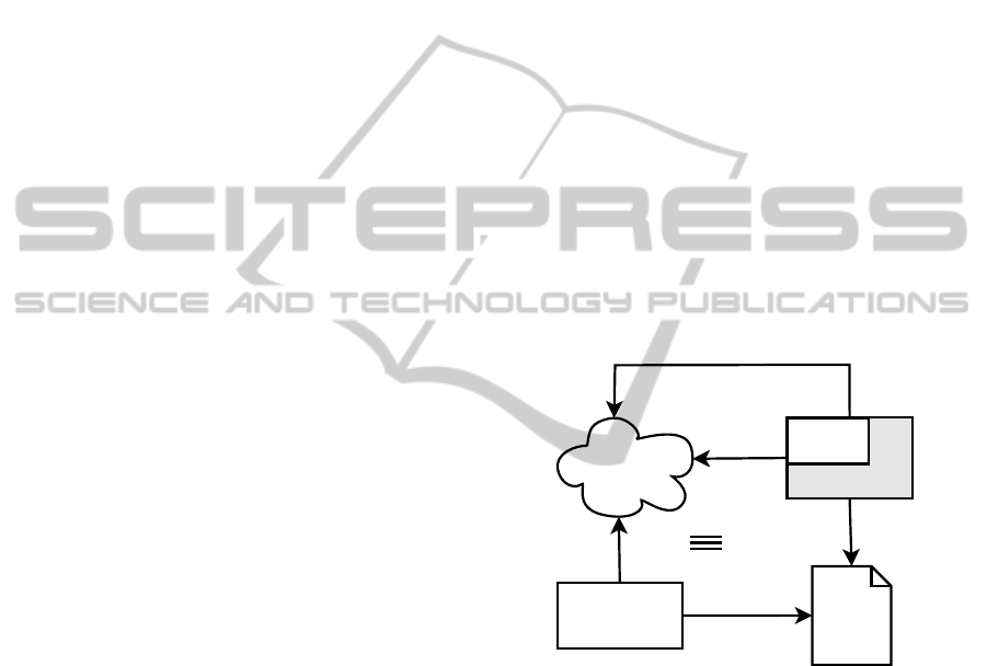
Figure 1, depicts the approach taken by this work.
The intended model that the user aims at, is modelled
in TXStates. This model acts as a guide for develop-
ing the JSXM model that is used for generating test
cases. The test cases then are executed by the TXS-
tates DSL in order to prove equivalence of the two
models. When this is achieved, the same test cases
act as simulation scenarios, that visualized by TXS-
tates allow the user to observe the behaviour of the
developedsimulation in a range of situations, and thus
validate the model.
Agent Model
JSXM
models
models
Test
Cases
generates
executes
validates (visualization)
NetLogo
TXStates
Figure 1: The SXM Approach to Simulation Development.
3 MODELLING AND TESTING
AGENTS AS SXMS
State machines have been used extensively to de-
rive agent simulation implementations since they pro-
vide a rather intuitive way to model agent behaviour.
SXMs extend finite state machines with a memory
structure and transitions labelled with functions and
thus allow more powerful modelling of a system. For
completeness, the definition of SXMs is presented be-
low.
Definition 1. A
stream X-machine
(Holcombe and
Ipate, 1998) is an 8-tuple
Z = (Σ, Γ, Q, M, Φ, F, q
0
, m
0
)
ICAART2015-InternationalConferenceonAgentsandArtificialIntelligence
88

where:
• Σ and Γ are the input and output alphabets, re-
spectively.
• Q is the finite set of states.
• M is the (possibly) infinite set called memory.
• Φ is a set of partial functions ϕ; each such func-
tion maps an input and a memory value to an
output and a possibly different memory value, ϕ :
M × Σ → Γ× M.
• F is the next state partial function, F : Q×Φ → Q,
which given a state and a function from the type
Φ determines the next state. F is often described
as a state transition diagram.
• q
0
and m
0
are the initial state and initial memory
respectively.
Intuitively, a SXM Z can be thought as a finite au-
tomaton with the arcs labelled by functions from the
set Φ. The automaton A
Z
= (Φ,Q,F, q
0
) over the al-
phabet Φ is called the associated finite automaton (ab-
breviated associated FA) of Z and is usually described
by a state-transition diagram.
Definition 2. A computation state is defined as the
tuple (q,m), with q ∈ Q and m ∈ M. The computation
step is defined as (q,m)
ϕ
⊢ (q
′
,m
′
) with q,q
′
∈ Q and
m,m
′
∈ M such that ϕ(m,σ) = (γ,m
′
) and F(q,ϕ) =
q
′
. The computation is the series of computation steps
when all inputs are applied to the initial computation
state (q
0
,m
0
).
An agent can be considered as an entity that maps
its current percepts and state to an action. Thus, in
order to model the behaviour of an agent using SXMs,
a mapping of the concepts of the former to the latter
is necessary. However, due to the structure of SXMs
this mapping is rather clear and straightforward:
• The input alphabet Σ forms the agent percepts.
• The agent’s internal world representation and all
parameters that affect its behaviour are mapped to
the SXM memory M and current state. In other
words M holds agent beliefs, while with appropri-
ate encoding of states, it can also hold the agent’s
current goal.
• Agent behaviour is modelled as a set of functions
Φ and the transition diagram F.
• Finally, agent actions are mapped to the output Γ.
3.1 Background on Testing with SXM
SXMs have the significant advantage of offering a
testing method that under certain design-for-test con-
ditions ensures the conformance of a system under
test (SUT) to a specification. This section provides
details regarding test case generation to ensure com-
pleteness of the paper.
The goal of the testing method is to devise a finite
test set X ⊂ Σ
∗
of input sequences that produce iden-
tical results when applied to the specification and the
SUT only if they both compute identical functions.
The main assumption that needs to be made for the
SUT is that it consists of correct elementary compo-
nents, i.e. the processing functions are correctly im-
plemented. Furthermore, it is estimated that the num-
ber of states in the SUT is n
′
≥ n, where n is the num-
ber of states of the specification. Let k = n
′
− n.
Input sequences attempt to drive the SUT to all the
states, then exercise from those states paths of transi-
tions of length k + 1 and finally uniquely identify the
reached states. If the output sequences produced by
the SUT are different than the ones produced by the
specification faults are revealed.
The SXM testing method (Ipate and Holcombe,
1997; Holcombe and Ipate, 1998) relies on the fol-
lowing design-for-test condition:
• Output-distinguishability. Processing functions
should be distinguishable by their different out-
puts on some memory-input pair, i.e. for every
φ
1
,φ
2
∈ Φ, m ∈ M and σ ∈ Σ such that (m,σ) ∈
dom φ
1
and (m, σ) ∈ dom φ
2
, if φ
1
(m,σ) = (γ,m
1
)
and φ
2
(m,σ) = (γ,m
2
) then φ
1
= φ
2
.
The testing method for SXMs is an extension
of the W-method for finite state machines. The
test generation is a two stage process: (1) the W
method (Chow, 1978) is applied on the associated au-
tomaton A
Z
to produce a set T ⊆ Φ
∗
of sequences
of processing functions, which are then (2) translated
into sequences of inputs for Z using a so-called test
function t : Φ
∗
→ Σ
∗
.
T is obtained by constructing a state cover S and
a characterization set W of A
Z
. S ⊆ Φ
∗
contains se-
quences to reach all states of A
Z
, while W ⊆ Φ
∗
con-
tains sequences to distinguish between any two dis-
tinct states of A
Z
. Each sequence t ∈ T consists of
three sub-sequences, i.e., t = syw, where s ∈ S drives
the automaton to a specific state, y ∈ Φ
∗
attempts to
exercise transition-paths up to length of k + 1 and w
distinguishes the resulting state from any other state.
Thus T = SΦ[k + 1]W = S(
S
0≤i≤k+1
Φ
i
)W.
Based on (Ipate and Holcombe, 1997), the max-
imum number of test sequences, i.e., card(T), is
less than n
2
· r
k+2
/(r − 1), where n = card(Q), r =
card(Φ). The total length l of the test set is less than
card(T) · n
′
, where n
′
= k+ n.
Since SXMs have memory, there may exist se-
quences of processing functions that are accepted by
the associated automaton A
Z
but they cannot be driven
FromFormalModellingtoAgentSimulationExecutionandTesting
89

by any input sequence. These sequences are called
non-realizable.
Definition 3. A sequence p ∈ Φ
∗
is called realizable
in q and m if p ∈ L
A
Z
(q) and ∃s ∈ Σ
∗
such that (m, s) ∈
dom kpk. The set of realizable sequences of Z in q
and m is notated as LR
Z
(q,m). Let LR
Z
be defined as
LR
Z
(q
0
,m
0
).
The definitions of the state cover and the charac-
terization sets are extended to handle realizable se-
quences of processing functions.
A state is r-reachable if it can be reached by a re-
alizable sequence p ∈ LR
Z
.
Definition 4. A set S
r
⊆ LR
Z
is called a r-state cover
of Z if for every r-reachable state q of Z there exists a
unique p ∈ S
r
that reaches the state q.
The set of memory values that can be attained at
a state q is notated as MAtt(q) and it consists of all
memory values that are the result of realizable se-
quences that end at state q, i.e. MAtt(q) = {m ∈
M| ∃p ∈ LR
Z
and ∃s ∈ Σ
∗
,kpk(m
0
,s) = (g,m)}.
Any two states have to be separable, i.e. distin-
guished by two realizable sequences with overlapping
domains.
Definition 5. A pair of states (q
1
,q
2
) is separable
if there exists a finite set of sequences Y such that
∀m
1
∈ MAtt(q
1
),m
2
∈ MAtt(q
2
), there exists p
1
∈
LR(q
1
,m
1
) ∩ Y and p
2
∈ LR(q
2
,m
2
) ∩ Y such that
dom p
1
∩ dom p
2
6=
/
0.
Essentially, at each state the same sequence of in-
puts will trigger one of the two sequences of process-
ing functions. By the observed outputs we can tell
which sequence of processing functions has been trig-
gered and thus identify the state.
Definition 6. A set W
s
⊆ Φ
∗
is called a separating set
of Z if it separates (distinguishes) between every pair
of separable states of Z.
If S
r
reaches all states of Z and W
s
separates all
pairs of states in Z. the testing method reduces to a
variant of the W-method:
T = UW
s
= ((S
r
Φ[k+ 1]) ∩ L
A
Z
)W
s
Furthermore, the testing method requires that all
sequences of U = (S
r
Φ[k + 1]) ∩ L
A
Z
are realizable,
i.e. it is required that U ⊆ LR
Z
. Note that the se-
quences of processing functions of maximum length
k+ 1 that follow the r-state cover are limited to those
that are accepted by the associated automaton.
The final test suite for checking functional equiv-
alence is:
X = t(T) = t(UW
s
)
The sequences of inputs in X ⊂ Σ
∗
are fed to the
SXM in order to produce the corresponding expected
sequences of outputs Y ⊂ Γ
∗
.
4 MAS SIMULATION WITH
TXStates
TXStates is an internal DSL for the NetLogo Agent
Simulation environment, that allows encoding SXM
agent specifications in a natural manner. Before pre-
senting TXStates a brief presentation of NetLogo is
provided in order to clarify the terminology provided
in the rest of the paper and place the present work in
context.
NetLogo is “a cross-platform multi-agent pro-
grammable modelling environment” (Wilensky,
1999) aiming at MAS simulation. In NetLogo, the
environment consists of a static grid of patches,
useful for describing the environment, since they
are capable of interacting with other entities. This
“world” is inhabited by turtles that are entities that
“live” and interact within it. They are organised in
groups called breeds, i.e. user defined teams sharing
some characteristics. Finally, links are entities
that “connect” two turtles representing usually a
spatial/logical relation between them.
Patches, turtles and links carry their own internal
state, stored in a set of system and user-defined vari-
ables local to each agent. By the introduction of an
adequate set of patch variables, a sufficient descrip-
tion of complex environments can be achieved. The
definition of turtle specific variables allows the for-
mer to carry their own state and facilitates encoding
of complex behaviour.
Agent behaviour can be specified by the domain
specific NetLogo programming language, supports
two main programming constructs: functions (called
reporters) and procedures. The language includes
a large set of primitives for turtles motion, environ-
ment inspection, classic program control (ex. branch-
ing), etc. NetLogo v5 introduced tasks, the version of
anonymous functions or closures of NetLogo. Rea-
soning about time is supported through ticks, each tick
corresponding to a discrete execution step. Finally,
the programming environment offers simple GUI cre-
ation facilities that minimize the time required to de-
velop a simulation.
Although a powerful modelling tool, as indicated
by the constantly increasing number of publications
that use NetLogo as the platform of choice, NetLogo
has been criticised for not providing modelling con-
structs that allow encoding of more complex agents.
The TXStates DSL provides an answer to this and
contributes to the list of tools to support complex
agent behaviour encoding, such as BOD (Bryson,
2003) and IODA (Kubera et al., 2011), adding the di-
mension of automatic test case generation for agents.
There is a continuous debate whether one mod-
ICAART2015-InternationalConferenceonAgentsandArtificialIntelligence
90

elling tool is better than another. We have invested
considerable time to develop a good number of mod-
els in NetLogo and we found it appropriate for the
applications we have encountered, that is, biologi-
cal or biology-inspired agents with spatial character-
istics and their emergent behaviour. Notwithstand-
ing the simulation tool, this work can be immediately
adopted since it refers to the general concept of test-
ing through a formal specification.
4.1 TXStates Models SXMs
The TXStates provides support for encoding all mod-
elling constructs of SXM definition presented in sec-
tion 3. Ease of encoding was a veryimportant require-
ment, since in most cases in multi-agent simulations,
the development is iterative, since the emergent phe-
nomena that manifest in such as setting demand a trial
and error approach and constant changes in the model.
In essence, TXStates extends the NetLogo pro-
gramming language, with the necessary constructs to
build executable SXM models. The DSL is inter-
nal since it relies on the syntax of NetLogo and all
the code is implemented using the NetLogo language,
possibly at the cost of execution speed, but offering
tight coupling with the underlying language and with-
out interrupting the normal development cycle a mod-
eller follows in the specific platform. In essence, we
decided not to implement an external DSL, since apart
from the SXM model the developer has to provide to
specify agent behaviour, in order to arrive to an exe-
cutable simulation, other parts of the simulation, such
as environment setup, visualization, agent perception
mechanisms, have to be defined as well, thus having
an external DSLwould mean that the developerwould
have to work on two different platforms simultane-
ously.
The implementation relies on storing agent spe-
cific information on turtle-own variables, since each
agent must carry its own agent (execution) state.
Thus, memory M is mapped to a data structure stored
in a turtle-own variable called memory that consists of
attribute - value pairs. The DSL provides special care
for its management to facilitate model development.
For instance, in Figure 2 the procedure
x-mem-set
<V> <Val>
is a destructive update with value
<Val>
for attribute (or memory element)
<V>
.
In a similar manner, percepts that correspond to
SXM input Σ are stored in a variable percept and al-
though percepts is a relatively simple data structure,
the library provides a set of programming constructs
(Figure 2) to access/add percepts depending on envi-
ronment changes. Please note that it is the model de-
veloper’s responsibility to update the former in each
(1) MEMORY PRIMITIVES
x-init-memory
x-mem-initial-var <V> <Val>
x-mem-set <V> <Val>
x-mem-value <V>
(2) PERCEPT PRIMITIVES
x-add-percept <P>
x-percept-add-value <P> <Val>
x-has-percept? <P>
x-percept-value <P>
x-oneof-percept-value <P>
x-all-percept-values <P>
Figure 2: TXStates primitives for X-Machine memory han-
dling and percept updates.
simulation cycle.
Finally, there is a class of turtle variables that
the library uses internally and should not be changed
in any way by the developer of the model, since
they store information relevant to state invocation
and the corresponding code (in fact function calls
as NetLogo tasks) of each state. Examples include
active-states
turtle variable that holds the active
X-Machine state.
Probably the most interesting features of the DSL
are encoding the set of functions Φ, output Γ, states
Q and the transition diagram F. These are described
in the sections that follow.
4.2 Encoding Agent Actions
Functions of the set Φ (referred as X-Function) are
encoded as NetLogo reporters (NetLogo jargon for
functions), that return results in a specific format, the
latter being handled by the TXStates meta-interpreter.
There are no arguments to these reporters since by
X-Machine definition, functions operate on input and
memory and produce output and memory updates and
thus all these functions are assumed to work on the
memory structures described in the previous section.
Since X-functions are partial functions, they must
return (report in NetLogo terms) either output and
memory updates, prefixed by a special success token
or a special failure token. These special tokens are
employed by the TXStates meta-interpreter to deter-
mine possible transitions. Thus, each such NetLogo
reporter should return either:
•
x-false
, a keyword handled by the meta-
interpreter, indicating that the function is not ap-
plicable (failure token),
•
x-true <xmOutput> <xmMemUpdates>
, indicat-
ing that the function is applicable success token
and will produce
<xmOutput>
output and change
memory according to the
<xmMemUpdates>
.
FromFormalModellingtoAgentSimulationExecutionandTesting
91

The
<xmOutput>
corresponds to the X-Machine
output Γ and in the simulation context represents the
list of actions that the agent has to perform. These
actions are specified as NetLogo tasks, annotated by
the keyword
x-action
, that get to be executed if the
function is selected by the interpreter for a state tran-
sition. Delimiters
#<
and
>#
mark the start and the
end of the list of actions. Thus
<xmOutput>
has the
form:
#< x-action task [...]
x-action task [...] >#
The second “argument”
<xmMemUpdates>
is a list
of memory updates, i.e. invocations of
x-mem-set
commands described in 2, again delimited by
#<
and
>#
. Thus,
<xmMemUpdates>
has the following form:
#< x-mem-set ...
x-mem-set ... >#
Empty
<xmOutput>
and
<xmMemUpdates>
are de-
noted as
#< >#
. It should be mentioned that the above
are lists, and not sets, i.e. the changes described ei-
ther as environment effects or memory updates will
be performed in the order they appear.
There are no limitations regarding the code that a
X-function can include, as long (a) it returns results
of the type indicated above (b) does not include side-
effects, i.e. changes in the simulation environment
and agent state, apart from those explicitly encoded
as return values of an
x-true
function result. Since
the meta-interpreter evaluates all functions, producing
possible memory and output results and then decides
which function to apply, the presence of side-effects
outside return values of the function would produce
unexpected behaviour. Allowing arbitrary NetLogo
code in an X-function contributes towards the tight in-
tegration to the TXStates DSL to the underlying plat-
form.
A X-function encoded as a NetLogo reporter is
given in Figure 3. The function checks whether the
agent has certain percepts, executes the NetLogo pro-
cedure
bee-move
and updates the memory variable
“position” to reflect the change in the “beliefs” of the
agent that it has moved. The condition that appears
in the
ifelse
is known as a “guard” and defines the
domain of the partial function.
4.3 State and Transition Diagram
Specification
Probably the most important aspect of the TXStates
DSL is the ease by which states Q and the transition
diagram F are encoded, since the latter allows directly
encoding X-Machines in NetLogo.
A single transition labelled by an X-function is
represented as:
# x-func <XMFunc> goto <StateName>
where
<XMFunc>
is a NetLogo X-Function as de-
scribed in 4.2 and
<StateName>
is the name of a state,
i.e. a simple string. An SXM that consists of multiple
states each state being a set of transitions and can be
defined as follows:
x-diagram
state <StateNameA>
# x-func <XMFunc A1> goto <StateName A1>
...
# x-func <XMFunc An> goto <StateName An>
end-state
state <StateNameK>
# x-func <XMFunc K1> goto <StateName K1>
...
# x-func <XMFunc Kn> goto <StateName Kn>
end-state
end-x-diagram
In such a specification, the first state that appears
in the definition of the
x-diagram
is considered to be
the initial state q
0
.
In order to relate an X-Machine definition to a spe-
cific breed of turtles to the execution environment, the
list of state definitions given above, is placed inside a
NetLogo reporter the name of which is formed by ap-
pending thestring “state-def-of-” to the breed name of
the turtles. For instance, if the breed is called ”bees”
the X-Machine controlling the behaviour of persons
will be given be a reporter named“state-def-of-bees”.
4.4 Executing the Agent Specification
Executing the agent specifications presented in the
previous section is the responsibility of the TXStates
meta-interpreter. The latter is invoked by calling
the
execute-state-machines
command, usually in
each simulation cycle. Before invocation, the user
must ensure that the agent percepts been updated,
through appropriate calls of the corresponding primi-
tives in Figure 2.
The meta-interpreter is responsible for handling
state transitions and action execution and implements
the computation described in Definition 2, with each
invocation of the
execute-state-machines
com-
mand corresponding to a single computation step of
Definition 2. Thus at each cycle, the meta-interpreter:
1. Forms the list of functions Φ
state
, that label transi-
tions in the current SXM state q, i.e. Φ
state
= φ ∈
Φ : (q,φ,q
′′
) ∈ F, in the order they appear in the
agent specification.
ICAART2015-InternationalConferenceonAgentsandArtificialIntelligence
92

to-report moveTowardsAttackFormation
ifelse
x-percept-value "hornet" and x-mem-value "alert" = "hiveInDanger" and
patch-distance x-percept-value "hornetPos" x-mem-value "position"
> patch-distance x-percept-value "hornetPos" x-percept-value "closerToHornet"
[report x-true
#< x-action task [bee-move x-percept-value "closerToHornet"] >#
#< x-mem-set "position" x-percept-value "closerToHornet"
># ]
[report x-false]
end
Figure 3: Example of a X-Function demonstrating use of TXStates Primitives.
2. Form the list Φ
trig
that contains all functions from
Φ
state
whose guards are satisfied. In the case that
the trigger list is empty, execution ends with an
error message.
3. Select the first function φ
i
from the list Φ
trig
.
4. Execute actions specified by φ
i
.
5. Apply memory updates specified by φ
i
.
6. Perform a transition to state q
′
that corresponds to
function (q,φ
i
,q
′
) ∈ F.
In order to simplify the encoding of guards an or-
dering is imposed to the function application; cur-
rently the selection function chooses the first function
in the state definition that triggers in step 3. This im-
poses a priority ordering on the transitions in a state,
with the transitions that appear higher in the state def-
inition having a larger priority. Imposing a priority
ordering ensures that the model is always determinis-
tic, i.e. it is always clear which state transition will
occur, an issue that is very important when dealing
with simulation environments, since it maintains re-
producibility. In the corresponding JSXM model, the
same behaviour is achieved by having a richer set of
guards in the functions.
The TXStates DSL
1
is provided as a NetLogo li-
brary that users can include in their models and spec-
ify behaviour. The major advantage of using TXS-
tates is that developers can develop models in an
iterative fashion, modifying the X-Machine model
quite easily and viewing directly the results of their
changes. Thus, complex model development can be
greatly facilitated.
5 CASE STUDY: MODELLING
THE JAPANESE BEE
The working example we selected in the present
work concerns the behaviour of Japanese bees un-
der the presence of a giant Asian Hornet scout in the
1
http://users.uom.gr/∼iliass/projects/TXStates/
hive (Ono et al., 1995). The phenomenon is an ex-
cellent example of collective behaviour under attack
in insects, since bees form the so called “bee ball”
around the scout hornet, and by doing so increase the
temperature inside the ball to a level non tolerable by
the hornet, but tolerable by the bee itself.
We have implemented a simulation using SXMs
that mimic the behaviour of both the hornet and the
bees during this phenomenon. Rather informally,
bees that do not perceive any danger, are in a non-
alert state, i.e. they keep working as usual. Upon
perception of a hornet in the hive, bees start moving
towards the hornet in order to form the attack assem-
blage. However, since the perception radius of bees
is limited and in order to engage as large a popula-
tion as possible, bees become aware (“inAlert”) when
perceiving another bee approaching the hornet, or an-
other bee alerted. Bees in alert that do not directly
perceive the hornet try to follow an approaching bee
or move randomly. While approaching, the bee has to
detect when it reached the attack formation: this case
occurs either when it is close to the bee, or when there
is a bee in its adjacent patches (neighbourhood) is an
attacking bee. Upon reaching the attack formation,
the bee starts the attack, i.e. produces heat if the envi-
ronment temperature is below 49
o
C, and does noth-
ing otherwise. Obviously, since the hornet moves and
possibly kills other bees, bees attacking haveto under-
stand whether the hornet has been relocated, in order
to adjust their position.
Modelling such a phenomenon in an agent based
simulation is rather straightforward, having bees and
the scout hornet modelled as a single agent. The
model has been studied before in (Kefalas et al.,
2009) and we closely follow the approach authors
have taken in that paper, although providing a differ-
ent implementation and a modified state diagram.
The behaviour of the bee is modelled as a set of
states, as for example workInHive, inAlert, attacking,
etc. reflecting the state of the bee under the presence
of a hornet in the hive, or other bees in alert. The state
transition diagram is shown in Figure 4. This diagram
was encoded in the TXStates DSL quite naturally as
FromFormalModellingtoAgentSimulationExecutionandTesting
93

expected. Due to space limitations, part of this encod-
ing is shown below.
to-report state-def-of-bees
report
x-diagram
state "workInHive"
# x-func "attackedByHornet" goto "killed"
# x-func "seeHornet"
goto "approachingHornet"
# x-func "perceiveDanger" goto "inAlert"
# x-func "keepWorking" goto "workInHive"
end-state
... (more states)
state "killed"
# x-func "beeDying" goto "killed"
end-state
end-diagram
end
As shown in the diagram of Figure 4, state transi-
tions are labelled by functions. For instance the func-
tion in Figure 3 implemented in TXStates labels the
self transition of the state “approachingHornet”. In-
put reflects information the agent perceives from the
environment. For example when the agent perceives a
hornet, the tuple (hornet,true) is member of the input
of the agent and this becomes true when the hornet is
positioned inside the radius of perception of the bee.
The NetLogo implementation of the Bee model
using TXStates is approximately 290 lines of code
including the state diagram and the SXM functions,
while the code for the hornet and the set up of the
environment is approximately 170 lines.
6 CASE STUDY: GENERATING
THE TEST CASES
JSXM (Dranidis et al., 2012) is a tool, developed in
Java, that allows the specification of SXM models,
their animation and most importantly automated test
case generation. The test cases that are generated by
JSXM are in XML format and theyare independent of
the technology or programming language of the im-
plementation.
In the following sections we briefly describe the
JSXM modelling language and the associated tool
suite.
2
6.1 The Model in JSXM
The JSXM modelling language is an XML-based lan-
guage with Java in-line code. The states and the tran-
2
The tool can be downloaded from http://www.jsxm.org
sitions are described in XML. An extract of the JSXM
code for representing the state transition diagram of
Figure 4 is provided below:
<states>
<state name="workInHive" />
<state name="inAlert" />
<state name="approachingHornet" />
<state name="attacking" />
<state name="killed" />
</states>
<initialState state="workInHive" />
<transitions>
<transition from="workInHive"
function="attackedByHornet"
to="killed" />
<transition from="workInHive"
function="seeHornet"
to="approachingHornet" />
...
</transitions>
The input and the output symbols are also de-
scribed in XML code.
<input name="percept">
<arg name="temperature" type="xs:byte"/>
<arg name="freePosX" type="xs:byte"/>
<arg name="freePosY" type="xs:byte"/>
<arg name="deadHornet" type="xs:boolean"/>
<arg name="hornet" type="xs:boolean"/>
<arg name="hornetPosX" type="xs:byte"/>
<arg name="hornetPosY" type="xs:byte"/>
<arg name="closerToHornetX" type="xs:byte"/>
<arg name="closerToHornetY" type="xs:byte"/>
...
<arg name="lethalBite" type="xs:boolean"/>
</input>
The memory and the body of the processing func-
tions are written in in-line Java code. This allows the
definition of any complex Java data structure as the
memory of the system.
<memory>
<declaration>
byte positionX;
byte positionY;
byte hornet_posX;
byte hornet_posY;
</declaration>
<initial >
positionX = 0;
positionY = 0;
hornet_posX = -1;
hornet_posY = -1;
</initial>
</memory>
Processing functions are specified by defining
their inputs, outputs, preconditions (specifying the
domain of the function) and effects on the memory.
Due to space limitations only one processing function
is shown.
ICAART2015-InternationalConferenceonAgentsandArtificialIntelligence
94

workInHive
keepWorking
killed
attackedByHornet
inAlert
perceiveDanger
approachingHornet
seeHornet
beeDying
seeDeadHornet
followApproachingBee
searchingHornet
seeHornet
seeDeadHornet
attackedByHornet
lostHornet
moveTowardsAttackFormation
moveRandom
attacking
arrivedCloseToHornet
joinAttackFormation
seeDeadHornet
attackedByHornet
lostHornet
hornetRelocated
produceHeat
maintainTemp
.
.
attackedByHornet
Figure 4: The state diagram representing the Japanese bee. Labels in transitions represent X-functions that based on percepts
and memory are triggered to alter the environment and the agent’s internal memory.
<function name="seeHornet" input="percept"
output="action" xsi:type="OutputFunction">
<precondition>
!percept.get_lethalBite()
&& percept.get_hornet()
&& !percept.get_deadHornet()
&& abs(positionX-percept.get_hornetPosX())
+abs(positionY-percept.get_hornetPosY())<10
</precondition>
<effect>
hornet_posX = percept.get_hornetPosX();
hornet_posY = percept.get_hornetPosY();
action.msg = "saw_Hornet";
</effect>
</function>
6.2 Test Generation
The JSXM tool implements the SXM testing method
(extended W-method) for the generation of the test
set. For the test generation process the modeller needs
to provide:
• a JSXM specification of the SXM model Z.
• an r-state cover S
r
and a separating set W
s
• the estimated difference k of states between the
SUT and the specification.
The r-state cover for the specific case study con-
sists of the following sequences of processing func-
tions: hi, hattackedByHorneti, hperceiveDangeri,
hseeHorneti, hseeHornet,arrivedCloseToHorneti.
All states of the state diagram are reached by these
sequences.
The separating set W
s
consists of the follow-
ing sequences: hattackedByHorneti, hbeeDyingi,
hkeepWorkingi, hseeDeadHorneti, hlostHorneti,
hsearchingHorneti, hfollowApproachingBeei,
hmoveTowardsAttackFormationi, hhornetRelocatedi,
hproduceHeati, hmaintainTempi. At each reached
state the execution of these processing functions
produces outputs that uniquely separate the reached
state by all the other states.
It should be noted that the r-state cover is com-
puted automatically by the JSXM tool. However, au-
tomatically computing the separating set W
s
is still an
open research issue.
For the input-output test cases to be produced, all
the input sequences are fed to the JSXM animator,
which acts as an oracle, and the resulting output se-
quences are recorded. The resulting test cases (pairs
of input and output sequences) are stored in a XML
file in a programming language independent format.
For the specific case study the JSXM tool has gener-
ated 62 test cases for k = 0.
6.3 From Test Cases to Simulation
Scenarios
The test cases produced by the JSXM tool, are then
processed in order to produce the simulation scenar-
ios used for validation. Since the input to each JSXM
function actually describes the state of the environ-
ment, appropriate NetLogo code was developed to set
up the exact state of the environment described. For
instance in the case of the test generated by JSXM
FromFormalModellingtoAgentSimulationExecutionandTesting
95

<call>
<function name="seeHornet" />
<input name="percept">
<temperature type="xs:byte">30
</temperature>
<freePosX type="xs:byte"> 0
</freePosX>
<freePosY type="xs:byte"> 1
</freePosY>
<deadHornet type="xs:boolean">false
</deadHornet>
<hornetPosX type="xs:byte"> 0
</hornetPosX>
<hornetPosY type="xs:byte"> -9
</hornetPosY>
...
<lethalBite type="xs:boolean"> false
</lethalBite>
<beeInAlert type="xs:boolean"> false
</beeInAlert>
</input>
<output name="action">
<msg type="xs:string">saw_Hornet</msg>
</output>
</call>
Figure 5: Part of a test sequence generated by the JSXM
tool. In the specific setting, the bee is expected to follow the
transition guarded by the “seeHornet” function and output
that it perceived a hornet.
shown in Figure 5, execution of the code places the
bee in position (0,0), sets the temperature to 30, and
places a live hornet at positions (0,-9). Then the agent
TXStates implementation is executed and the result-
ing actions are matched against the output of the test
case, while visually providing feedback to the mod-
eller involving the state change of the bee. Thus the
modeller can validate that this is the expected be-
haviour of the bee in the specific scenario.
7 RELATED WORK
From the various Multi-Agent Systems (MAS) design
methodologies that exist, relatively few deal explic-
itly with simulation design, and among these even
fewer are applicable for producing NetLogo code.
The Behavior Oriented Design (BOD) (Bryson, 2003)
and the Interaction-Oriented Design of Agent simu-
lations (IODA) (Kubera et al., 2011) are examples
of such methodologies that are also currently sup-
ported by corresponding NetLogo tools. Going into
the specifics of both these methodologies exceeds the
scope of this section work, however, they both lack
support for any automated test generation process.
A number of DSL and DMSL approaches to pro-
gramming MAS have been reported in the literature.
For instance in (Hahn, 2008) and (Challenger et al.,
2014) present approaches to domain specific mod-
elling languages (DSML), for developing multi agent
systems. These approaches differ from TXStates
since they focus on describing MAS models using
high level concepts such as agent roles, interactions,
etc. and provide and model transformations to code.
The present work addresses mainly and problem of
modelling and validating a single agent in a MAS
simulation setting, and provide what could be con-
sidered as unit testing/validation of that agent model.
To the best of our knowledge, these modelling frame-
works do not address this problem.
A number of diverse approaches for testing agent
based systems are found in the literature. As men-
tioned, our focus lies mainly on two aspects. On one
hand, whilst testing the communication and coordina-
tion in a society of agents is of interest when develop-
ing MAS, testing a single agent against its specifica-
tion is of paramount importance. Under this scope,
a number of unit testing frameworks have been pro-
posed. However, there is a variety of views as to what
constitutes a unit to be tested. On the other hand, tools
that offer automated test generation and execution ca-
pabilities are limited.
Caire et al. (Caire et al., 2004) presented a testing
framework that offers a skeleton code for the devel-
oper to build test cases, considering as a testable unit
either a single agent or any of its internal behaviours
as a black box. The framework was developed as
part of the PASSI (Cossentino and Potts, 2002) devel-
opment methodology. An agent system’s behaviour
was initially captured in a Multi-Agent Zoomable Be-
haviour Description diagram - introduced by the au-
thors - which is in essence an Activity Diagram ex-
tended with Agent UML notations. The tool also pro-
vides a test agent for automatic test case execution.
SUnit (Tiryaki et al., 2007) is a framework that
is built on top of the Seagent (Dikenelli et al., 2005)
MAS development platform. The tool allows for test-
ing of agent interactions and plans, which are consid-
ered as the units to be tested. SUnit extends the JUnit
3
testing framework, and was developed with the pur-
pose of facilitating test driven development of MAS.
SUnit provides a mock agent infrastructure, which
the developer uses to automatically run the manually
written tests.
Coelho et al. (Coelho et al., 2006) suggest that the
modular unit in a MASis a single agent, and thus, pro-
pose the notion of a Mock Agent that is built specifi-
cally for testing the agent under test. Therefore, each
Mock Agent is a manual fake implementation of an
actual agent that interacts with the agent (role) under
3
http://junit.org/
ICAART2015-InternationalConferenceonAgentsandArtificialIntelligence
96

test. Coehlo et al. in (Coelho et al., 2007) later pro-
posed JAT (Jade Agent Testing Framework), a test au-
tomation framework built on top of the JADE
4
MAS
development platform, and is aimed to facilitate the
developer in creating the Mock Agent code and auto-
matically executing the test scenarios.
The above work focuses on automating the exe-
cution rather than the generation of test cases. The
latter capability is provided in the work of Zhang et
al. (Zhang et al., 2007) who proposed a model-based
testing framework that allows for automatic test gen-
eration and execution. The framework uses the design
artefacts produced with the Prometheus (Padgham
and Winikoff, 2005) agent developmentmethodology.
The framework was integrated (Zhang et al., 2008)
in the Prometheus Design Tool (PDT)
5
. In this case,
an agent consists of events, plans and belief-sets, and
each of these were considered as a unit to be tested by
the authors, in contrast to our work that tests the dy-
namic internal behaviour of a single agent as a whole
rather than its individual components.
A different approach on model based test genera-
tion was provided by Seo et al. (Seo et al., 2004) and
Zheng and Alagar (Zheng and Alagar, 2005). The for-
mer used Statecharts extended with roles descriptions,
event types and memory to model a MAS. Based on
the diagram, all possible transitions to all concrete
events were manually calculated, and then fed to a
tool developed by Seo et al. that generated the test
sequences. The latter used Extended State Machines
(ESM) to formally model an agent and then used this
model to generate a set of unit test cases. Each test
set consisted of a set of state cover sequences and a
set of transition cover sequences. However, in both
these cases, no further discussion exists on automat-
ing the test execution process. More importantly, in
our case, the SXM testing theory provides for more
coverage than state and transition coverage, addition-
ally allowing for proof of functional equivalence of
the models.
Automated test case generation and execution are
useful in supporting model verification to some sig-
nificant extend. Visualization on the other hand is
considered as one of the most predominant valida-
tion techniques for simulations. A validation frame-
work proposed by (Kl¨ugl, 2008) identifies animation
assessment as one of the basic methodological ele-
ments. To further support a preliminary model val-
idation, Xiang et al. (Xiang et al., 2005) applied a
model-to-model comparison technique. They initially
built a conceptual model of the Natural Organic Mat-
ter (NOM) evolution, and then implemented a corre-
4
http://jade.tilab.com/
5
http://www.cs.rmit.edu.au/agents/pdt/
sponding simulation. By using various verification
methods and by visualizing 450 simulation runs of
their model with different random seeds, they vali-
dated their model against the conceptual one. They
subsequently compared their results with another ex-
isting implementation of the same conceptual model.
The authors argue that the good agreement between
the results of these two different implementation sup-
ports the validity of their implementation. In our case,
the generated test cases facilitate the validation via vi-
sualization process, by providing the developer with
an easy way of selecting specific test scenarios of in-
terest.
8 CONCLUSIONS
This work presents a systematic approach to the prob-
lem of developing, testing and validating agent simu-
lations. Towards this direction, the current work:
• describes a DSL that can be used to specify and
execute an SXM model, that encodes the be-
haviour of an agent in the simulation, and
• shows how an existing tool for automated test case
generation that employs the same formal mod-
elling approach, can be used for generating a set
of “simulation scenarios”.
Thus this paper demonstrates how the SXM for-
mal modelling technique is employed in a practical
setting to develop simulations.
One of our immediate aims is to provide a way to
semi-automatically translate large parts of the TXS-
tates model to the JSXM modelling language. Addi-
tionally, a tool for semi-automatically testing equiv-
alence of the two models, since in the current state
manually crafted code had to be written that processes
the output files of JSXM and perform the equivalence
test with the TXStates agents.
Furthermore, it is our intention to extend this ap-
proach to other agents simulation and agent program-
ming platforms. One future direction is to investigate
whether BDI agents can be modelled as SXMs and
apply the specific testing approach to such systems.
REFERENCES
Allan, R. J. (2010). Survey of agent based modelling and
simulation tools. Technical Report DL-TR-2010-007,
DL Technical Reports.
Bryson, J. J. (2003). The behavior-oriented design of mod-
ular agent intelligence. In Agent technologies, infras-
tructures, tools, and applications for e-services, pages
61–76. Springer.
FromFormalModellingtoAgentSimulationExecutionandTesting
97

Caire, G., Cossentino, M., Negri, A., Poggi, A., and Turci,
P. (2004). Multi-agent systems implementation and
testing. In In Fourth International Symposium: From
Agent Theory to Agent Implementation. Citeseer.
Challenger, M., Demirkol, S., Getir, S., Mernik, M., Kar-
das, G., and Kosar, T. (2014). On the use of a domain-
specific modeling language in the development of
multiagent systems. Engineering Applications of Ar-
tificial Intelligence, 28:111–141.
Chow, T. S. (1978). Testing software design modelled by
finite state machines. IEEE Transactions on Software
Engineering, 4:178–187.
Coelho, R., Cirilo, E., Kulesza, U., von Staa, A., Rashid,
A., and Lucena, C. (2007). Jat: A test automation
framework for multi-agent systems. In ICSM 2007.
IEEE International Conference on Software Mainte-
nance, 2007., pages 425–434. IEEE.
Coelho, R., Kulesza, U., von Staa, A., and Lucena, C.
(2006). Unit testing in multi-agent systems using
mock agents and aspects. In Proceedings of the 2006
international workshop on Software engineering for
large-scale multi-agent systems, pages 83–90. ACM.
Cossentino, M. and Potts, C. (2002). A case tool supported
methodology for the design of multi-agent systems.
In International Conference on Software Engineering
Research and Practice (SERP’02).
Davidsson, P., Holmgren, J., Kyhlbck, H., Mengistu, D.,
and Persson, M. (2007). Applications of agent based
simulation. In Antunes, L. and Takadama, K., edi-
tors, Multi-Agent-Based Simulation VII, volume 4442
of Lecture Notes in Computer Science, pages 15–27.
Springer Berlin / Heidelberg.
Dikenelli, O., Erdur, R. C., and Gumus, O. (2005). Seagent:
a platform for developing semantic web based multi
agent systems. In Proceedings of the 4th International
Joint Conference on Autonomous Agents and Multia-
gent Systems, pages 1271–1272. ACM.
Dranidis, D., Bratanis, K., and Ipate, F. (2012). JSXM:
A tool for automated test generation. In Software
Engineering and Formal Methods, pages 352–366.
Springer.
Hahn, C. (2008). A domain specific modeling language
for multiagent systems. In Proceedings of the 7th
international joint conference on Autonomous agents
and multiagent systems-Volume 1, pages 233–240. In-
ternational Foundation for Autonomous Agents and
Multiagent Systems.
Holcombe, M. and Ipate, F. (1998). Correct Systems: Build-
ing a Business Process Solution. Springer, London.
Ipate, F. and Holcombe, M. (1997). An integration testing
method that is proven to find all faults. International
Journal of Computer Mathematics, 63:159–178.
Kefalas, P., Stamatopoulou, I., Sakellariou, I., and Eleft-
herakis, G. (2009). Transforming communicating
x-machines into p systems. Natural Computing,
8(4):817–832.
Kl¨ugl, F. (2008). A validation methodology for agent-based
simulations. In Proceedings of the 2008 ACM sympo-
sium on Applied computing, pages 39–43. ACM.
Kubera, Y., Mathieu, P., and Picault, S. (2011). IODA: an
interaction-oriented approach for multi-agent based
simulations. Autonomous Agents and Multi-Agent
Systems, 23(3):303–343.
Nikolai, C. and Madey, G. (2009). Tools of the trade:
A survey of various agent based modeling platforms.
Journal of Artificial Societies and Social Simulation,
12(2):2.
Ono, M., Igarashi, T., Ohno, E., and Sasaki, M. (1995). Un-
usual thermal defence by a honeybee against mass at-
tack by hornets. Nature, 377(6547):334–336.
Padgham, L. and Winikoff, M. (2005). Developing intel-
ligent agent systems: A practical guide, volume 13.
John Wiley & Sons.
Sakellariou, I., Kefalas, P., and Stamatopoulou, I. (2014).
Evacuation simulation through formal emotional
agent based modelling. In ICAART 2014 - Proceed-
ings of the 6th International Conference on Agents
and Artificial Intelligence, Volume 2, pages 193–200.
SciTePress.
Seo, H.-S., Araragi, T., and Kwon, Y. R. (2004). Model-
ing and testing agent systems based on statecharts. In
Applying Formal Methods: Testing, Performance, and
M/E-Commerce, pages 308–321. Springer.
Tiryaki, A. M.,
¨
Oztuna, S., Dikenelli, O., and Erdur, R. C.
(2007). Sunit: A unit testing framework for test
driven development of multi-agent systems. In Agent-
Oriented Software Engineering VII, pages 156–173.
Springer.
Wilensky, U. (1999). NetLogo. Center for Con-
nected Learning and Computer-Based Mod-
eling, Northwestern Univ., Evanston, IL.
http://ccl.northwestern.edu/netlogo/.
Xiang, X., Kennedy, R., Madey, G., and Cabaniss, S.
(2005). Verification and validation of agent-based sci-
entific simulation models. In Agent-Directed Simula-
tion Conference, pages 47–55.
Zhang, Z., Thangarajah, J., and Padgham, L. (2007). Au-
tomated unit testing for agent systems. ENASE, 7:10–
18.
Zhang, Z., Thangarajah, J., and Padgham, L. (2008). Au-
tomated unit testing intelligent agents in pdt. In Pro-
ceedings of the 7th international joint conference on
Autonomous agents and multiagent systems: demo pa-
pers, pages 1673–1674. International Foundation for
Autonomous Agents and Multiagent Systems.
Zheng, M. and Alagar, V. (2005). Conformance testing of
BDI properties in agent-based software. In APSEC
’05:12th Asia-Pacific Software Engineering Confer-
ence, 2005, pages 457–464.
ICAART2015-InternationalConferenceonAgentsandArtificialIntelligence
98
